Data must be secure, accessible, and always available. Build and operate a storage network that can do it all with Cisco MDS 9000 Series.
Protect your investment
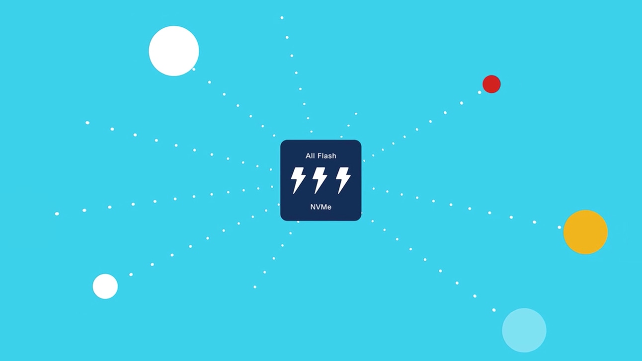
Choose from solutions that offer 64G-capable speed and high performance for NVMe/FC and all-flash array storage environments.
Deep visibility
Troubleshoot faster and streamline operations with the industry's first and only on-chip analytics for NVMe, Fibre Channel, and FC-SCSI.
Work smarter with automation
Reduce OpEx with DevOps integrations. Get real-time insights for faster end-to-end provisioning with industry API calling.
Safeguard your data
Protect your network with integrated anti-counterfeit security and secure-boot technology.
Find the model that fits your needs
Cisco MDS 9700 Series directors
Scale, performance, integrated analytics, and the industry's highest port density SAN director.
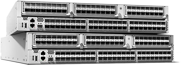
MDS 9300 Series switches
Next-generation high-density fabric switches with integrated analytics and telemetry.
MDS 9200 Series switches
High-performance SAN extension, disaster-recovery, intelligent fabrics, and multiprotocol connectivity.
MDS 9100 Series switches
Flexible and agile, highly available and secure, and easy to use with visibility to every flow.
Storage area networking modules
Modules with a wide range of capabilities, speeds, and switching for SAN architectures.
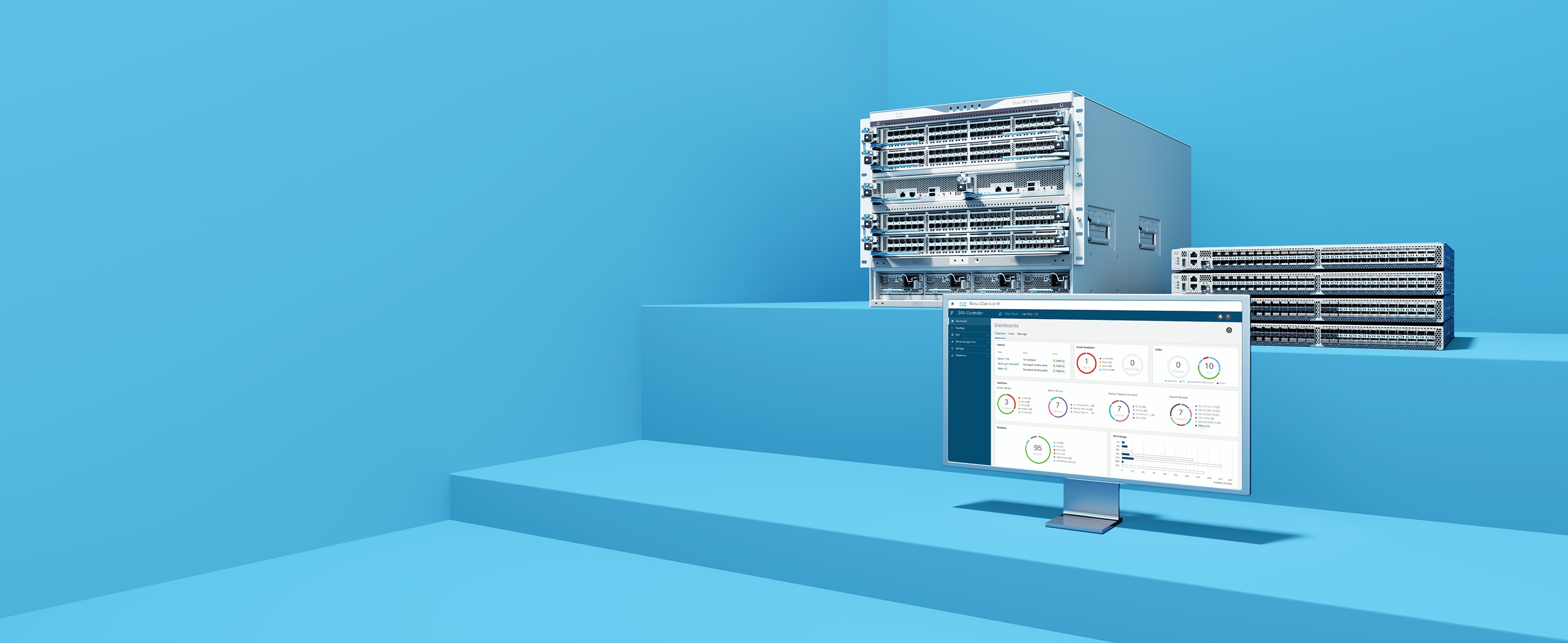
Cisco Nexus Dashboard Fabric Controller
Complete SAN, LAN, and IPFM automation, extensive visibility, and consistent operations.
Cisco SAN Analytics
Visibility and data-driven guidance, for faster troubleshooting and optimized infrastructure.