- Cisco Service and Application Module for IP Overview
- Hardware Features
- Software/Firmware Features
- Packet Egress Through IXP
- MAC Propagation to IXP for IPv4/IPv6 Addresses
- IXP Configuration Using Packet Trailers for CSG2 R5.0
- IPC Load Management
- PPC Configuration File Storage on the Supervisor Engine
- Remote Console and Logging
- Session Support
- Health Monitoring
- High Availability
- Hot Fabric Sync
- IEEE 802.1 Q-in-Q VLAN Tag Termination
- Cisco Software Application Support
Cisco Service and Application Module for IP Overview
This chapter describes the Cisco Service and Application Module for IP (SAMI).
•![]() Cisco Service and Application Module for IP Overview
Cisco Service and Application Module for IP Overview
•![]() System Requirements and Specifications
System Requirements and Specifications
Cisco Service and Application Module for IP Overview
The following versions of the Cisco SAMI are available:
•![]() Cisco Service and Application Module for IP (WS-SVC-SAMI-BB-K9)
Cisco Service and Application Module for IP (WS-SVC-SAMI-BB-K9)
•![]() spare Cisco Service and Application Module for IP (WS-SVC-SAMI-BB-K9=)
spare Cisco Service and Application Module for IP (WS-SVC-SAMI-BB-K9=)
Additionally, a 4-GB memory option is available (MEM-SAMI-6P-4GB).
SAMI 4.0 will support 4GB DIMMs in addition to the presently supported 2GB DIMMs.
The SAMI hardware limits the number of ranks to 2.

Note ![]() Please reference the documentation for the Cisco software application you are using to determine if the 4-GB memory option is supported.
Please reference the documentation for the Cisco software application you are using to determine if the 4-GB memory option is supported.
The Cisco SAMI, is a high-performance Cisco software application module that occupies one slot in the Cisco 7600 Series Router platform.
With an IXP2800 network processor flow-distributor running at 1.4 GHz, and six PowerPCs (PPC) running an instance of the same version of a Cisco software application at 1.25 GHz, the Cisco SAMI offers a parallel architecture for Cisco software applications such as the Cisco Content Services Gateway - 2nd Generation (CSG2), the Cisco Gateway GPRS Support Node (GGSN), the Cisco Mobile Wireless Home Agent (HA), the Cisco Wireless Security Gateway (WSG), the Cisco Broadband Wireless Gateway and Cisco IP Transfer Point (ITP), and the Cisco Long Term Evolution (LTE) Gateway products.
A session to each Cisco software application on a SAMI PCC can be established from the supervisor to configure, monitor, and troubleshoot the application.
Figure 1-1 illustrates the SAMI architecture:
Figure 1-1 SAMI Architecture
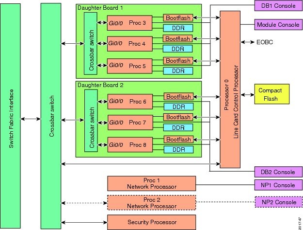
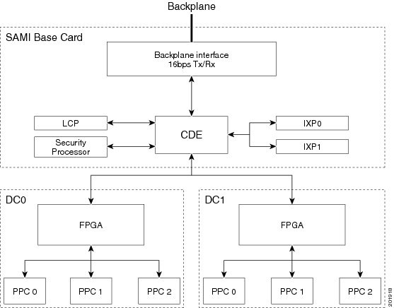
Figure 1-2 illustrates the flow of data on the SAMI.
Figure 1-2 SAMI Data Flow
The following sections describe the primary SAMI hardware and software features:
Hardware Features
The SAMI provides the following hardware features:
•![]() Classification and Distribution Engine
Classification and Distribution Engine
Backplane Interface
The SAMI backplane interface is a switch fabric-enabled interface, with a supported bandwidth of 16 Gbps TX/RX.
Line Card Control Processor
On the SAMI, a BCM1250 dualcore CPU running at 700 MHz provides the following functionality as the line card control processor (LCP):
•![]() Brings up the module and various basecard elements and the SAMI daughter cards (DC0 and DC1).
Brings up the module and various basecard elements and the SAMI daughter cards (DC0 and DC1).
•![]() Interfaces with compact flash to store and retrieve daughter card images.
Interfaces with compact flash to store and retrieve daughter card images.
•![]() Interfaces with supervisor engine during an image bundle upgrade, and automatically upgrades the PPC ROMMON images during the upgrade.
Interfaces with supervisor engine during an image bundle upgrade, and automatically upgrades the PPC ROMMON images during the upgrade.
•![]() Provides an Ethernet Out-of-Band Channel (EOBC) interface to the daughter card PPCs that supports features such as the session command, the execute-on command, and the remote console and logging (RCAL) feature.
Provides an Ethernet Out-of-Band Channel (EOBC) interface to the daughter card PPCs that supports features such as the session command, the execute-on command, and the remote console and logging (RCAL) feature.
•![]() Monitors the module (for example, temperature and path health) and manages the various components on the module.
Monitors the module (for example, temperature and path health) and manages the various components on the module.
•![]() Provides a 32-bit 33 MHz PCI interface to the network processor (IXP1) and daughter cards (DC0 and DC1).
Provides a 32-bit 33 MHz PCI interface to the network processor (IXP1) and daughter cards (DC0 and DC1).
•![]() Sends error messages to the supervisor engine.
Sends error messages to the supervisor engine.
Classification and Distribution Engine
The SAMI classification and distribution engine (CDE) classifies and distributes packets to various source and destinations on the board and provides the Cisco 7600 Series Router chassis backplane interface.
The data flows (Figure 1-2) are as follows:
•![]() Backplane interface to the network processor (IXP0/1)—Ingress traffic is forwarded to IXPs based on the CDE VLAN destination configuration.
Backplane interface to the network processor (IXP0/1)—Ingress traffic is forwarded to IXPs based on the CDE VLAN destination configuration.
•![]() Network processor (IXP0/1 to daughter card 1 (DC0) and daughter card 2 (DC1)—IXP0 classifies traffic and forwards to DC0/DC1 PPCs.
Network processor (IXP0/1 to daughter card 1 (DC0) and daughter card 2 (DC1)—IXP0 classifies traffic and forwards to DC0/DC1 PPCs.
•![]() DC0/DC1 to backplane interface—Egress traffic is forwarded to backplane interface. For some applications such as PDSN, LTE PGW and LTE SGW, and the CSG 2, DC0/DC1 also sends packets to Network Processor. Details are available in the respective applications guides.
DC0/DC1 to backplane interface—Egress traffic is forwarded to backplane interface. For some applications such as PDSN, LTE PGW and LTE SGW, and the CSG 2, DC0/DC1 also sends packets to Network Processor. Details are available in the respective applications guides.
•![]() LCP to/from DC0/DC1—Control/management traffic.
LCP to/from DC0/DC1—Control/management traffic.
•![]() DC0 to DC1/DC1 to DC0—Inter-processor, inter-daughter card Cisco software application traffic.
DC0 to DC1/DC1 to DC0—Inter-processor, inter-daughter card Cisco software application traffic.
Network Processor
A Intel IXP2800 network processor (IXP0/1) on the baseboard load balances which classifies ingress packets for forwarding to the PPCs on the daughter cards.
Daughter Cards
The two SAMI daughter cards (DC0 and DC1) provide the following primary components:
•![]() First In, First Out (FIFO) queuing interfaces to the baseboard.
First In, First Out (FIFO) queuing interfaces to the baseboard.
•![]() Complex programmable logic device (CPLD) that provides peripheral access.
Complex programmable logic device (CPLD) that provides peripheral access.
•![]() Field programmable gate array (FPGA) that classifies and forwards ingress traffic from the network processor to the PPCs, and forwards of egress traffic from the PPCs to the backplane interface.
Field programmable gate array (FPGA) that classifies and forwards ingress traffic from the network processor to the PPCs, and forwards of egress traffic from the PPCs to the backplane interface.
•![]() Six PowerPC (PPC) SC8548H CPUs at 1.25 GHz that support:
Six PowerPC (PPC) SC8548H CPUs at 1.25 GHz that support:
–![]() 2 GB double data rate 2 (DDR2) synchronous dynamic RAM (SDRAM) per PPC at 250 megahertz (MHz), upgradable to one 4 GB dual in-line memory module (DIMM) each.
2 GB double data rate 2 (DDR2) synchronous dynamic RAM (SDRAM) per PPC at 250 megahertz (MHz), upgradable to one 4 GB dual in-line memory module (DIMM) each.
–![]() SAMI is enhanced with 4GB DRAM memory modules for each PPC giving a total of 24GB memory per card. But, the available memory is limited to 3264MB per PPC (19GB per card), due to the limitation of 32 bit architecture of the PPC.
SAMI is enhanced with 4GB DRAM memory modules for each PPC giving a total of 24GB memory per card. But, the available memory is limited to 3264MB per PPC (19GB per card), due to the limitation of 32 bit architecture of the PPC.
–![]() 32 MB bootflash in which to store ROMMON, nonvolatile variables, crashinfo, and user filesystems.
32 MB bootflash in which to store ROMMON, nonvolatile variables, crashinfo, and user filesystems.
–![]() One instance of the same Cisco software application image. (Six instances of the same image per SAMI.)
One instance of the same Cisco software application image. (Six instances of the same image per SAMI.)
Each PPC on a SAMI runs the same version of a Cisco software application image. This is the default installation during an image upgrade. Different Cisco software application images can run on separate SAMIs within the same Cisco 7600 chassis.
There are two types PPC operating systems that can run on the Cisco SAMI PPCs - the Cisco IOS or the Common OS Services Linux Infra (COSLI) operating system. The Cisco software application determines the PPC operating system used.
All PPCs can function together as one entity.
The supervisor engine and the SAMI can be configured to store the running configuration of each PPC on the supervisor engine, enabling a SAMI to be replaced while retaining PPC configurations.
•![]() Daughter card data path—32-bit FIFO at 125 MHz DDR (8 Gbps).
Daughter card data path—32-bit FIFO at 125 MHz DDR (8 Gbps).
•![]() PPC data path—16-bit FIFO at 125 MHz single data rate (SDR) (2 Gbps).
PPC data path—16-bit FIFO at 125 MHz single data rate (SDR) (2 Gbps).
Security Processor
The Nitrox-II security processor is used for packet encryption and decryption, as well as encapsulation and decapsulation offload.
Compact Flash Memory
Configuration, software images, and core files are stored in the compact flash memory.
To generate core files from the TP, configure the singleip tftp-baseport port command. This command is available for single IP SAMI
Software/Firmware Features
Note ![]() Support for the following features is dependent upon the Cisco software application running on the Cisco SAMI PPCs. To determine if a Cisco SAMI feature is supported by the application, refer to the application documentation.
Support for the following features is dependent upon the Cisco software application running on the Cisco SAMI PPCs. To determine if a Cisco SAMI feature is supported by the application, refer to the application documentation.
The SAMI provides the following software features:
•![]() PCI Based IXP IPC
PCI Based IXP IPC
•![]() Configuring Multiple IXPs
Configuring Multiple IXPs
•![]() MAC Propagation to IXP for IPv4/IPv6 Addresses
MAC Propagation to IXP for IPv4/IPv6 Addresses
•![]() IXP Configuration Using Packet Trailers for CSG2 R5.0
IXP Configuration Using Packet Trailers for CSG2 R5.0
•![]() PPC Configuration File Storage on the Supervisor Engine
PPC Configuration File Storage on the Supervisor Engine
•![]() IEEE 802.1 Q-in-Q VLAN Tag Termination
IEEE 802.1 Q-in-Q VLAN Tag Termination
•![]() Cisco Software Application Support
Cisco Software Application Support
Packet Egress Through IXP
This feature allows an enabled packet to go through IXP in the PPC egress path. Whether the packet goes through IXP is determined internally by the application running over the PPC.
MAC Propagation to IXP for IPv4/IPv6 Addresses
This feature enables propagation of MAC addresses to the IXP. In the IXP dataplane, when the IXP forwards the packet, it needs to know the MAC address of the next-hop. The MAC resolver helps by maintaining an updated record of IP to MAC mapping using the data from ARP/IPv6 ND. It shares this MAC information with the IXP, which in turn helps the IXP to pick up the destination MAC for the packet.
This feature is an internal feature used to facilitate datapath acceleration, and not configurable by the user.
IXP Configuration Using Packet Trailers for CSG2 R5.0
The Packet Trailers feature allows the CSG to add additional data at the end of an IP packet. The CSG may use this to share some data with the IXP to facilitate an acceleration path. This feature is an internal feature used to facilitate datapath acceleration, and not configurable by the user.
IPC Load Management
The IPC Management feature identifies and monitors resources that are critical for the IPC. The number of IPC messages on the Cisco CSG2 application is expected to be high, thus the need to manage those messages.
PPC Configuration File Storage on the Supervisor Engine
The PPC Configuration File Storage on the Supervisor feature enables the startup configuration file of each of the SAMI PPCs to be stored in the supervisor engine bootflash. This feature enables a SAMI in a specific slot to be replace without losing the configurations associated with each of the PPCs on the SAMI.
For information about enabling this feature, see "Enabling the Supervisor to Store PPC Startup Configuration Files" section.
Remote Console and Logging
Remote console and logging (RCAL) enables operators to use the supervisor engine console as a single connection point from which to access the LCP and the PPCs on the SAMI daughter cards to control debugging, display show commands, and view logging output for the PPCs on the SAMI.
For information about configuring RCAL support, see "Configuring Remote Console and Logging" section.
Session Support
From the supervisor engine console, sessions to the SAMI LCP, network processor (IXP0), and the PPCs can be established.
Note ![]() The Cisco software application running on the SAMI PPCs might not support a console connection. To determine if an application supports a connection, see the documentation for that application (see the "Related Documentation" section).
The Cisco software application running on the SAMI PPCs might not support a console connection. To determine if an application supports a connection, see the documentation for that application (see the "Related Documentation" section).
Specifically, the following sessions, listed by number, can be established:
|
|
|
|---|---|
0 |
LCP |
1 |
IXP0 |
2 |
IXP1 (for future use) |
3 |
DC0, PPC0 |
4 |
DC0, PPC1 |
5 |
DC0, PPC2 |
6 |
DC1, PPC0 |
7 |
DC1, PPC1 |
8 |
DC1, PPC2 |
For information about establishing sessions, see "Establishing Console Sessions" section. For information on establishing a console connection, see "Establishing a Console Connection on the SAMI" section.
Health Monitoring
A SAMI PPC can be configured to send probes to monitor the health of its path to the network processor, or to monitor the health of all paths to the supervisor engine.
If a PPC does not receive a response to a probe that it has sent, it determines that there is an issue with a path. If this condition occurs, the PPC can be configured to send a notification to the LCP that instructs the LCP to reset the SAMI.
For more information about configuring health monitoring on the SAMI, see the "Configuring Health Monitoring" section.
High Availability
High availability is provided through a stateful switchover redundancy scheme on the supervisor engine.
For information on configuring redundancy on the Cisco 7600, refer to the Cisco 7600 router documentation in the "Related Documentation" section.
Hot Fabric Sync
The switch fabric module functionality is built into the Supervisor Engine 720 and the RSP720. When a supervisor engine switchover occurs, a fabric switchover also occurs. During this process, the line cards must resynchronize with the new active switch fabric. The Hot Fabric Sync feature, which is enabled by default, keeps both the active and standby fabric in sync at the same time, minimizing the switchover time and thereby minimizing any impact on switch fabric traffic. To verify the fabric sync status of active and standby supervisors, enter the show fabric status command.
With Cisco IOS 12.2(33)SRC on the supervisor, this feature is supported on the Cisco 7603-S, Cisco 7604, Cisco 7606-S, and Cisco 7609-S routers. With Cisco IP Transfer Point, Cisco IOS Release 12.2(25)IRA or later, the Hot Fabric Sync feature is supported on the SAMI.
For more information about the Hot Fabric Sync feature, refer to the Cisco 7600 documentation in the "Related Documentation" section.
IEEE 802.1 Q-in-Q VLAN Tag Termination
The Cisco SAMI supports IEEE 802.1Q-in-Q VLAN Tag Termination.
Encapsulating IEEE 802.1Q VLAN tags within 802.1Q enables service providers to use a single VLAN to support customers who have multiple VLANs. The IEEE 802.1Q-in-Q VLAN Tag Termination feature on the subinterface level preserves VLAN IDs and keeps traffic in different customer VLANs segregated.
For information about configuring IEEE 802.1Q-in-Q VLAN Tag Termination support, see the Cisco IOS LAN Switching Configuration Guide, Release 12.2SR.
Cisco Software Application Support
Each of the PPCs on a SAMI runs an instance of the same version of a Cisco software application image. Multiple SAMIs running a different Cisco software application on its PPCs can be implemented within the same chassis.
Note ![]() There are two types PPC operating systems that can run on the Cisco SAMI PPCs - the Cisco IOS or the Common OS Services Linux Infra (COSLI) operating system. The Cisco software application determines the PPC operating system used.
There are two types PPC operating systems that can run on the Cisco SAMI PPCs - the Cisco IOS or the Common OS Services Linux Infra (COSLI) operating system. The Cisco software application determines the PPC operating system used.
The list of Cisco software applications supported on SAMI includes, but is not limited to, the following Cisco software applications:
•![]() Cisco Wireless Security Gateway, Release 1.0 or later.
Cisco Wireless Security Gateway, Release 1.0 or later.
•![]() Cisco Broadband Wireless Gateway, Cisco IOS Release 12.4(15)XL1 or later.
Cisco Broadband Wireless Gateway, Cisco IOS Release 12.4(15)XL1 or later.
•![]() Cisco Content Services Gateway 2, Cisco IOS Release 12.3(11)MD or later.
Cisco Content Services Gateway 2, Cisco IOS Release 12.3(11)MD or later.
•![]() Cisco GPRS Gateway Support Node, Cisco IOS Release 12.4(15)XQ or later.
Cisco GPRS Gateway Support Node, Cisco IOS Release 12.4(15)XQ or later.
•![]() Cisco Home Agent, Cisco IOS Release 12.4(15)XM or later.
Cisco Home Agent, Cisco IOS Release 12.4(15)XM or later.
•![]() Cisco IP Transfer Point, Cisco IOS Release 12.2(25)IRA or later.
Cisco IP Transfer Point, Cisco IOS Release 12.2(25)IRA or later.
•![]() Cisco Packet Data Serving Node, Cisco IOS Release 12.4(15)XR or later.
Cisco Packet Data Serving Node, Cisco IOS Release 12.4(15)XR or later.
Note ![]() The features supported on the Cisco SAMI PPC are dependent on the Cisco software application running on the SAMI PPCs. Refer to the Cisco software application documentation to determine if a feature is supported by the SAMI for the application.
The features supported on the Cisco SAMI PPC are dependent on the Cisco software application running on the SAMI PPCs. Refer to the Cisco software application documentation to determine if a feature is supported by the SAMI for the application.
See the "Related Documentation" section for a list of documents related to the Cisco software applications.
Front Panel Description
Figure 3 illustrates the front panel of the SAMI.
Figure 3 SAMI Front Panel
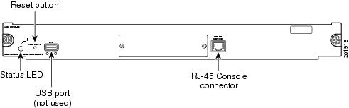
This section describes the following components on the front panel:
Status LED
When you power on the SAMI, it initializes various hardware components and communicates with the supervisor engine. The status LED indicates supervisor engine operations and initialization results. During the normal initialization sequence, the status LED changes from off to red, orange, and green.
Note ![]() For information about supervisor engine LEDs, see the Cisco 7600 Series Router Module Installation Guide.
For information about supervisor engine LEDs, see the Cisco 7600 Series Router Module Installation Guide.
Table 1 describes status LED operation.
Reset Button

The Reset button manually shuts down the SAMI. To properly shut down the SAMI to prevent data loss, enter the no power enable module command in configuration mode at the router CLI.
If the SAMI fails to respond to this command, shut down the module by using a small pointed object (such as a paper clip) to access the Reset button on the front panel of the SAMI. The shutdown procedure may take several minutes. The Status LED turns off when the module shuts down.
USB Port
The USB port is not used.
RJ-45 Console Connector
In general, the SAMI RJ-45 console port is not used except for possibly some specific cases of troubleshooting and recovery that might require accessing the LCP through the external console port.
System Requirements and Specifications
The following sections describe the system requirements and specifications for the SAMI:
System Requirements
Note ![]() The supervisor engine module and its Cisco IOS software image is dependent on the supervisor engine being used and the Cisco software application running on the Cisco SAMI processors.
The supervisor engine module and its Cisco IOS software image is dependent on the supervisor engine being used and the Cisco software application running on the Cisco SAMI processors.
For the hardware and software requirements of the Cisco software application you are running on the Cisco SAMI, refer to the documentation for that application.
Before you install the SAMI with preloaded software in the Cisco 7600 series router chassis, ensure that the chassis contains the following:
•![]() Any module that has ports to connect to the server and client networks.
Any module that has ports to connect to the server and client networks.
•![]() Supervisor Engine 720, with a Multilayer Switch Feature Card, running Cisco IOS Release 12.2(33)SRB1 and later.
Supervisor Engine 720, with a Multilayer Switch Feature Card, running Cisco IOS Release 12.2(33)SRB1 and later.
or
Cisco 7600 Series Supervisor Engine 32, with a Multilayer Switch Feature Card, running Cisco IOS Release 12.2(33)SRC and later. Supervisor Engine 32 support requires LCP ROMMON Version 12.2[121] and later on the Cisco SAMI.
For details on upgrading the Cisco IOS release running on the supervisor engine, refer to the "Upgrading to a New Software Release" section in the Release Notes for Cisco IOS Release 12.2SR.
For information about verifying and upgrading the LCP ROMMON image on the Cisco SAMI, see the "Manually Upgrading an LCP ROMMON Image" section.
The SAMI occupies a single slot in the Cisco 7600 Series Router chassis.
The maximum number of SAMIs supported in one chassis is dependent on the Cisco software application running on the SAMI PPCs. Therefore, for the maximum number of SAMIs supported in a chassis, refer to the application documentation (see the "Related Documentation" section).
For more information on the Cisco 7600 Series Router, see the Cisco 7600 Series Router Installation Guide:
http://www.cisco.com/en/US/products/hw/routers/ps368/prod_installation_guides_list.html
Power Requirements
The SAMI operates on power supplied by the Cisco 7600 Series Router. The SAMI power consumption is 300 watts (1024 BTU/hr).
Memory Requirements
The SAMI memory is not configurable.
Environmental Requirements
Table 1-2 lists the environmental requirements for the SAMI.
Physical Specifications
Table 1-3 lists the physical specifications of the SAMI.
|
|
|
|---|---|
Dimensions (H x W x D) |
1.2 x 14.4 x 16 in (3.0 x 35.6 x 40.6 cm) |
Weight |
12.15 lb. |
Agency Approvals
Emissions:
•![]() CE marking
CE marking
•![]() EN 55022, 1998, class A
EN 55022, 1998, class A
•![]() CISPR22, 1997, class A
CISPR22, 1997, class A
•![]() AS/NZS CISPR 22 class A
AS/NZS CISPR 22 class A
•![]() CFR47, Part 15, class A
CFR47, Part 15, class A
•![]() ICES 003 class A
ICES 003 class A
•![]() VCCI Class A
VCCI Class A
•![]() EN61000-3-2 Harmonic Current Emission
EN61000-3-2 Harmonic Current Emission
•![]() EN61000-3-3 Voltage Fluctuation and Flicker
EN61000-3-3 Voltage Fluctuation and Flicker
Immunity:
•![]() CE Marking
CE Marking
•![]() CISPR24, ITE-Immunity characteristics, Limits and methods of measurement
CISPR24, ITE-Immunity characteristics, Limits and methods of measurement
•![]() EN 55024, ITE-Immunity characteristics, Limits and methods of measurement
EN 55024, ITE-Immunity characteristics, Limits and methods of measurement
•![]() EN50082-1, Electromagnetic compatibility - Generic immunity standard
EN50082-1, Electromagnetic compatibility - Generic immunity standard
•![]() EN 300 386 Telecommunications Network Equipment (EMC)
EN 300 386 Telecommunications Network Equipment (EMC)
•![]() EN61000-6-1 Generic Immunity Standard
EN61000-6-1 Generic Immunity Standard
 Feedback