Provisioning Overview
Available Languages
Table Of Contents
Prerequisite Provisioning Information
Collecting External Device Addresses
Collecting SS7 Point Code Data
Collecting Media Gateway Controller Interface Card Data
Collecting SS7 Signaling Service Data
Collecting NAS Signaling Service Data
Collecting Trunk Data (Nailed)
Configuring the Media Gateway Controller
Provisioning Overview
The provisioning process described in this document applies to all solutions running Release 7 media gateway controller (MGC) software.
The provisioning overview prepares the Cisco MGC platform using the Cisco MGC software to communicate with the Signaling System 7 (SS7) network and with the media gateway controller exchange components that control bearer-traffic routing. This chapter contains the following sections:
•
Configuring the Media Gateway Controller
Provisioning Prerequisites
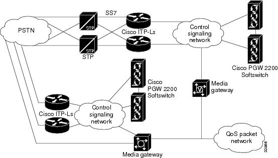
This section describes the tasks that must be completed before provisioning and describes the configuration information for the major components shown in Figure 1-1 that you need before you get started.
Figure 1-1 Provisioning Major Components for the Media Gateway Controller Software
Task Checklist
The following task checklist presents the steps you should have performed before using this guide.
Step 1
Plan your network configuration. A detailed network diagram is very helpful when provisioning.
•
Step 2
Set up your hardware components and install all required software.
•
•
•
•
•
Step 3
Complete provisioning worksheets, including filling in names and IP addresses of machines, names, attributes, and properties of components, and other necessary information.
•
Prerequisite Tasks
Before you start the provisioning process, you should prepare the Cisco MGC hardware and software as described in the following manuals:
•
•
Prerequisite Overview
The following list identifies one possible sequence of events for provisioning:
•
•
•
•
•
•
•
•
•
•
•
This guide provides worksheets to be copied and filled in with information specific to your system. Keep in mind that the steps described and the procedures performed will vary depending on your specific system.
Prerequisite Provisioning Information
Before you can complete the provisioning planning tables in Chapter 2, you must collect the following information:
•
•
•
•
Collecting External Device Addresses
For the control signaling network, each device attached to the network that has a unique IP address assigned to it must be listed in Table 1-1. In addition to the device IP address, a device name, and a description should also be provided.
Table 1-1 External Device Worksheet Example
(x.x.x.x)10.15.7.34
as5300-34
Media Gateway 5300-34
Collecting SS7 Point Code Data
The SS7 point codes are SS7 network addresses that uniquely identify every switch, Signal Transfer Point (STP), and MGC node on the SS7 network. To communicate with the SS7 network, you must get the SS7 point codes for your Cisco MGC and for every SS7 network device with which you are to communicate. At a minimum, you need at least one origination point code (OPC) for the MGC node and one destination point code (DPC) for the remote switch. If you plan to connect the Cisco MGC to STPs, you need an adjacent point code (APC) for every STP to which you connect.
Table 1-2 serves as a form where you can enter point codes for the OPCs, DPCs, and APCs you need to configure. The point code type and address are required for each SS7 network device. The description column is not required; however, you can use this column to note special information about a point code, such as its geographical location or network administrator.
Table 1-2 Point Code Worksheet Example
(OPC, APC, or DPC)
(x.x.x)OPC
214.135.034
2
MGC1 OPC
Collecting Media Gateway Controller Interface Card Data
When configuring connections between the Cisco MGC and Cisco Signaling Link Terminals (SLTs), media gateways (MGWs), or SS7 signaling points (SPs), you must be ready to enter information about the name, location, type, and address of the network interface cards. The interface card location and type are determined when the card is installed. The location is identified by the slot where the card is installed, and the type must be one of the types listed in the second column of Table 1-3
Table 1-4 Media Gateway Controller Interface Card Worksheet Example
EN
en-1
0
IP_Addr1
214.135.233
Ethernet IF 1
EN
en-2
1
IP_Addr2
214.135.235
Ethernet IF 2
1 Ethernet cards do not need a slot number.
Collecting SS7 Signaling Service Data
When configuring connections between the Cisco MGC and the SS7 signaling network, you must be ready to enter the following information about the SS7 service for the link to be created.
•
•
•
•
•
This SS7 signaling service link information can be listed in Table 1-5.
Table 1-5 SS7 Signaling Service Worksheet Example
SS7
ss7-135034
SS7 path to MGC1
ANSISS7_STANDARD
SS7
Collecting NAS Signaling Service Data
The signaling service between the Cisco MGC and the media gateway (MGW) needs to be defined for each pair attached to the network. You must be ready to enter the following information about the MGW signaling service:
•
•
•
•
•
This NAS signaling service link information can be listed in Table 1-6.
Table 1-6 NAS Signaling Service Worksheet Example
MGCP
MGW1
NAS1 from MGW1
BELL_1268_C3
MGC
Collecting Linkset Data
The linkset must be defined for each link between the Cisco MGC and the adjacent STP. If there are two adjacent STPs, you need to create two linksets (for example, LS01 and LS02). A linkset can contain from 1 to 16 links. You must be ready to enter the following information about each linkset:
•
•
•
•
•
•
This linkset information can be listed in Table 1-7.
Table 1-7 Linkset Worksheet Example
ls-stpa
APC
stpa
LS01 to STPA
SS7-ANSI
IP
ls-stpb
APC
stpb
LS02 to STPB
SS7-ANSI
IP
Collecting Cisco SLT Data
A link must be defined for each path from the Cisco SLT to the Cisco MGC. There must be one link (two maximum) for each Ethernet card in the Cisco MGC. The link corresponds to the linksets you previously created. You will create a linkset pair for each linkset that exists in your system. For example, if your system has two linksets, you will create two links for each linkset, resulting in your creating a total of four links. You must be ready to enter the following information about each Cisco SLT linkset:
•
•
•
•
•
•
•
•
This linkset information can be listed in Table 1-8.
Collecting C7 IP Link Data
A C7 IP link needs to be defined for each physical SS7 link that is connected to the SS7 network by the Cisco SLT. The C7 IP links correspond to linksets you previously created. You must be ready to enter the following information about the C7 IP link:
•
•
•
•
•
•
•
•
•
This C7 IP link information can be listed in Table 1-9.
Collecting IP Link Data
An IP link needs to be defined from the MGW to the Cisco MGC (MGC path), from the Cisco MGC to the SLT (SS7 MTP3 backhaul path), from one Cisco MGC to another Cisco MGC (EISUP path), and from each NAS to the Cisco MGC. You must be ready to enter the following information about the IP link:
•
•
•
•
•
•
•
•
This IP link information can be listed in Table 1-10.
Table 1-10 IP Link Worksheet Example
MGC-lnk34
en-1
IP_Addr1
2427
1
10.15.7.5
2427
mgcp-34
Collecting SS7 Route Data
You must define an SS7 route for each signaling route from the Cisco MGC to the PSTN switch. There must be an SS7 route for each linkset. You must be ready to enter the following information about the SS7 route to be created:
•
•
•
•
•
This SS7 route information can be listed in Table 1-11.
Table 1-11 SS7 Route Worksheet Example
rt1-stpa
Route direct to STPA
stpa
ls-stpa
opc
rt1-stpb
Route direct to STPB
stpb
ls-stpb
opc
Collecting SS7 Subsystem Data
An internal SS7 subsystem must be defined that connects each mated pair of STPs. This allows the Cisco MGC to route traffic over the C-links between the STPs. Thus if one STP fails, the Cisco MGC can route traffic over a C-link to the other STP. You must be ready to enter the following information about the SS7 subsystem:
•
•
•
•
•
•
•
•
•
This SS7 subsystem information can be listed in Table 1-12.
Collecting Trunk Data (Nailed)
During the provisioning process, you must define all of the bearer trunks that connect remote switches to the media gateway. Each remote switch is identified by its DPC, and each trunk is identified by the trunk ID. Table 1-13 provides space for you to provide the following information for the trunks coming from remote switches:
•
•
•
•
•
•
•
•
•
•
•
To save space, you might want to specify ranges of trunk IDs for each E1 or T1 connection. For large installations, you might want to make copies of this table or create your own worksheet with these columns.
The trunk ID must match the trunk ID used on the remote switch. The circuit identification code (CIC) is the SS7 value representing the trunk and must match the CIC value defined at the remote switch.
The destination span ID and destination time slot must match the trunk configuration values defined during Cisco MGC configuration. The destination span ID is defined when configuring T1 and E1 controllers and must match the value of the nfas_int parameter. T1 spans use time slots (channels) 1-24 and E1 spans use time slots 0-31. For more information on gateway configuration, see the Cisco SS7 Interconnect for Access Servers and Voice Gateways Solutions Media Gateway Installation and Configuration Guide.

Note
Configuring the Media Gateway Controller
Figure 1-2 shows the major components that must be defined in the Cisco MGC software before the media gateway can operate.
Figure 1-2 Major Configuration Components for the Media Gateway Controller Software
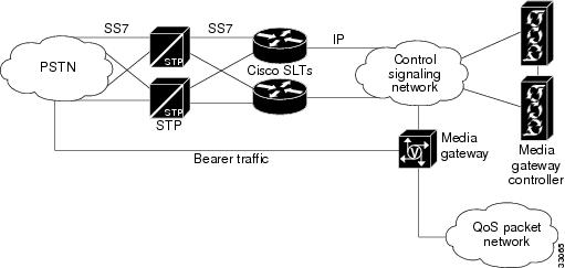
Figure 1-2 is a simplified view of the Cisco MGC; it does not show all system components and interdevice links. Most of the links shown represent multiple connections between devices.
The Cisco MGC shown in Figure 1-2 is the device that runs the Cisco MGC software. When you provision the Cisco MGC software, you are configuring communications between the Cisco MGC and at least one external SS7 Signaling Point (SP). Service Switching Points (SSPs) and Signal Transfer Points (STPs) are two types of SPs to which the Cisco MGC can connect. The Cisco MGC connects to SSPs directly using fully associated links (F-links) or indirectly through STPs using access links (A-links).
Within the media gateway, you must also provision the Cisco MGC connections to the MGW and define the bearer trunks that connect to the MGW. The connections between the Cisco MGC and the MGW are used to exchange signaling information between the SS7 network and the signaling protocol used on the quality of service (QoS) packet network. The bearer trunks transport call traffic between the remote switch and the Cisco MGC. This call traffic passes through the gateway to destinations on the QoS packet network.
To provision the Cisco MGC, you define software components for each of the entities shown in Figure 1-2. To define the connections between entities, you specify parameters for each component. Planning for provisioning is important, because many components cannot be configured until others have been provisioned. For example, you cannot provision links between two devices until you have provisioned the individual devices. "Planning for Provisioning," explains these dependencies and how to plan for provisioning in the correct sequence.
Provisioning Tools
The Cisco MGC includes two tools that you can use to provision the software:
•
•
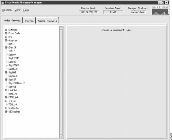
Figure 1-3 shows a sample CMM window that you can use to provision Cisco MGC components. CMM makes provisioning easier for less-experienced administrators by listing all the components that must be configured and by providing windows that display all configuration parameters for each component. Instructions for provisioning with TCM can be found in "TCM Provisioning Procedures for Release 7.3(x)" and "CMM Provisioning Procedures for Release 7.4(x)."
Figure 1-3 Sample Cisco Media Gateway Controller Manager Window
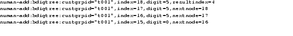
Example 1-1 shows a sample MML script, which is a collection of individual MML commands. Although MML provisioning requires more keystrokes, quick provisioning updates can sometimes be made faster with MML commands, because you don't have to go through the process of launching CMM. When you enter MML commands into a batch file, you can copy and paste configuration commands to speed command entry, and you can copy and modify MML scripts to configure additional SSPs. For information on provisioning with MML, refer to "Configuring with MML."
Example 1-1 Sample MML Script
You can use both CMM and MML to provision the Cisco MGC; however, only one configuration session can be supported at one time by either CMM or MML. Table 1-14 lists some of the features of CMM and MML and provides guidelines for selecting between the two tools.
The remaining chapters in this book describe how to plan for provisioning and provide sample provisioning plans for different Cisco MGC configurations (solutions). In "Planning for Provisioning," you will see component names listed for CMM and MML provisioning (these names are sometimes different). When you begin provisioning, you will provision components using the name that applies to the provisioning tool you are using.
 Feedback