- Server Monitoring and Management Tools
- Status LEDs and Buttons
- Preparing for Server Component Installation
- Installing or Replacing Server Components
- Replacing Hard Drives or Solid State Drives
- Replacing a Modular Drive Bay Assembly
- Replacing Fan Modules
- Replacing a Fan Tray
- Replacing Memory Risers
- Replacing DIMMs
- Replacing CPUs and Heatsinks
- Replacing the Motherboard RTC Battery
- Replacing a PCIe Riser Assembly
- Replacing an I/O Riser
- Replacing a Cisco Flexible Flash Drive
- Replacing a 10-Gb LOM Module
- Replacing a PCIe Card
- Replacing the RAID Controller Battery Backup Unit
- Installing a Trusted Platform Module
- Enabling the Intel Trusted Execution Technology (TXT) Feature For the TPM
- Replacing Power Supplies
- Enabling or Disabling the Internal USB Port
Maintaining the Server
This chapter describes how to diagnose server system problems using LEDs. It also provides information about how to install or replace hardware components, and it includes the following sections:
Server Monitoring and Management Tools
Cisco Integrated Management Interface (CIMC)
You can monitor the server inventory, health, and system event logs by using the built-in Cisco Integrated Management Controller (CIMC) GUI or CLI interfaces. See the user documentation for your firmware release at the following URL:
http://www.cisco.com/en/US/products/ps10739/products_installation_and_configuration_guides_list.html
Server Configuration Utility
Cisco has also developed the Cisco Server Configuration Utility for C-Series servers, which can aid and simplify the following tasks:
- Monitoring server inventory and health
- Diagnosing common server problems with diagnostic tools and logs
- Setting the BIOS booting order
- Configuring some RAID configurations
- Installing operating systems
This utility is pre-installed on an internal Cisco FlexFlash card inside the server (see Overview of the Pre-Installed Cisco FlexFlash Drive). You can also download the ISO from Cisco.com. See the user documentation for this utility at the following URL:
http://www.cisco.com/en/US/docs/unified_computing/ucs/sw/ucsscu/user/guide/20/SCUUG20.html
Status LEDs and Buttons
This section describes the location and meaning of LEDs and buttons and includes the following topics
Front Panel LEDs
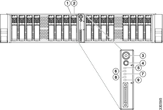
Figure 3-1 shows the front panel LEDs. Table 3-1 defines the LED states.
|
|
|
||
|
|
|
||
|
|
|
||
|
|
|
||
|
|
|
Rear Panel LEDs and Buttons
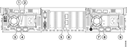
Figure 3-2 shows the rear panel LEDs and buttons.
Figure 3-2 Rear Panel LEDs and Buttons
|
|
|
10-Gb Ethernet link speed |
|
|
|
|
||
|
|
|
||
|
|
|
||
|
|
10-Gb Ethernet link status |
|
|
|
|
|---|---|
Internal Diagnostic LEDs
The server is equipped with a SuperCap voltage source that can activate internal component fault LEDs up to one half-hour after AC power is removed.
To use these LEDs to identify a failed component, press the front or rear Identification button (see Figure 3-1 or Figure 3-2) with AC power removed. An LED lights amber to indicate a failed component.
The server has internal fault LEDs for fan modules, CPU sockets, DIMMs, memory risers, the motherboard RTC battery, PCIe sockets, and Cisco FlexFlash cards.
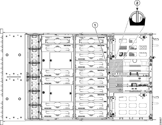
See Figure 3-3 for the locations of these internal LEDs.
Figure 3-3 Internal Diagnostic LED Locations
|
|
|
||
|
|
|
Cisco FlexFlash card fault LEDs (one on each card socket on the I/O riser) |
|
|
|
|
PCIe card fault LED (on motherboard adjacent to each PCIe slot) |
|
|
|
|
|
|
|
|---|---|
Preparing for Server Component Installation
This section describes how to prepare for component installation, and it includes the following topics:
- Required Equipment
- Shutting Down and Powering Off the Server
- Removing and Replacing the Server Top Cover
- Replaceable Component Locations
- Color-Coded Touch Points
Required Equipment
The following equipment is used to perform the procedures in this chapter:
Shutting Down and Powering Off the Server
The server can run in two power modes:
- Main power mode—Power is supplied to all server components and any operating system on your hard drives can run.
- Standby power mode—Power is supplied only to the service processor and the cooling fans and it is safe to power off the server from this mode.
You can invoke a graceful shutdown or an hard shutdown by using either of the following methods:
- Use the CIMC management interface.
- Use the Power button on the server front panel. To use the Power button, follow these steps:
Step 1![]() Check the color of the Power Status LED (see the “Front Panel LEDs” section).
Check the color of the Power Status LED (see the “Front Panel LEDs” section).
- Green—the server is in main power mode and must be shut down before it can be safely powered off. Go to Step 2.
- Amber—the server is already in standby mode and can be safely powered off. Go to Step 3.
Step 2![]() Invoke either a graceful shutdown or a hard shutdown:
Invoke either a graceful shutdown or a hard shutdown:

- Graceful shutdown—Press and release the Power button. The operating system performs a graceful shutdown and the server goes to standby mode, which is indicated by an amber Power Status LED.
- Emergency shutdown—Press and hold the Power button for 4 seconds to force the main power off and immediately enter standby mode.
Step 3![]() Disconnect the power cords from the power supplies in your server to completely power off the server.
Disconnect the power cords from the power supplies in your server to completely power off the server.
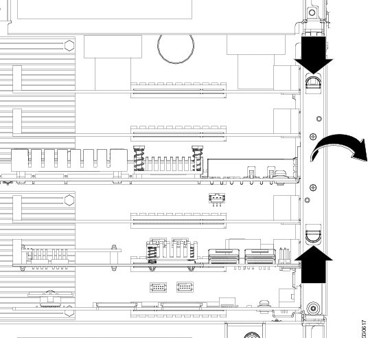
Removing and Replacing the Server Top Cover
To remove or replace the top cover of the server, follow these steps:

Tip![]() You do not have to remove the cover to replace hard drives or power supplies.
You do not have to remove the cover to replace hard drives or power supplies.
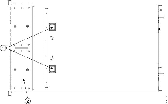
a.![]() Simultaneously press the two release buttons. See Figure 3-4.
Simultaneously press the two release buttons. See Figure 3-4.
b.![]() Push the top cover toward the server rear about one-half inch (1.27 cm), until it stops.
Push the top cover toward the server rear about one-half inch (1.27 cm), until it stops.
c.![]() Lift the top cover straight up from the server and set it aside.
Lift the top cover straight up from the server and set it aside.
a.![]() Place the cover on top of the server about one-half inch (1.27 cm) behind the lip of the chassis front cover panel. The cover should sit flat when the edge flanges are sitting in the grooves in the chassis.
Place the cover on top of the server about one-half inch (1.27 cm) behind the lip of the chassis front cover panel. The cover should sit flat when the edge flanges are sitting in the grooves in the chassis.
b.![]() Slide the top cover toward the front cover panel until it stops and the release buttons lock.
Slide the top cover toward the front cover panel until it stops and the release buttons lock.
Figure 3-4 Removing the Top Cover
|
|
|
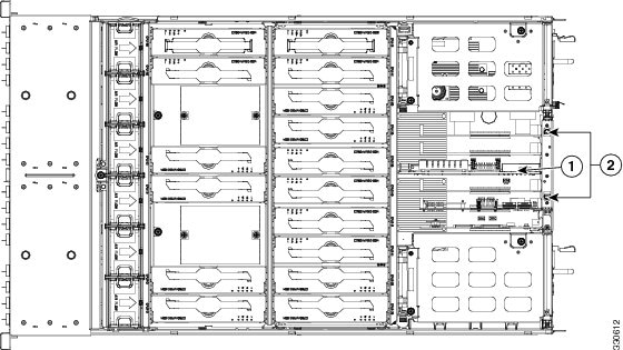
Replaceable Component Locations
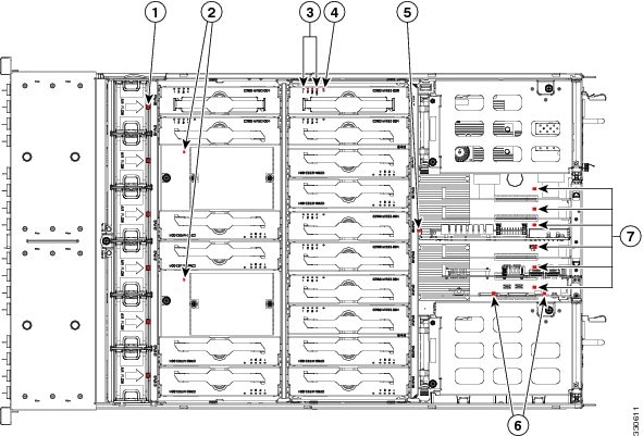
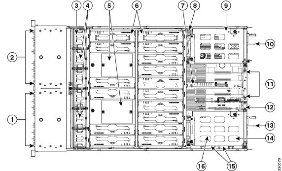
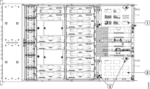
This section shows the locations of the components that are discussed in this chapter. The view in Figure 3-5 is from the top down with the top cover removed.
Figure 3-5 Replaceable Component Locations
|
|
Drive bay module 2 (up to eight 2.5-inch drives, hot-pluggable access through the front panel) |
|
|
|
|
Drive bay module 1 (up to eight 2.5-inch drives, hot-pluggable access through the front panel) |
|
|
|
|
|
PCIe slots 2–6 on motherboard (5) |
|
|
|
Drive backplane transition cards (up to 2 on chassis floor, not visible under fan tray in this view) |
|
|
|
|
|
||
|
|
Memory risers (16) |
|
|
|
|
|
Brackets for optional LSI RAID controller battery backup units (2) |
|
|
|
|
TPM socket (on motherboard, not visible under power supply in this view) |
Color-Coded Touch Points
This server has color-coded touch points that indicate thumbscrews and latches on replaceable and hot-swappable components.
- Hot-swappable components have green plastic touch points. This includes the internal cooling fans and the power supplies. (An exception is the drive trays on the front panel, which are hot-swappable but not green).
- Some replaceable but non-hot-swappable components have light-blue plastic touch-points. This includes memory risers, PCIe risers, PCIe slots, and fan tray.
Installing or Replacing Server Components

Warning![]() Blank faceplates and cover panels serve three important functions: they prevent exposure to hazardous voltages and currents inside the chassis; they contain electromagnetic interference (EMI) that might disrupt other equipment; and they direct the flow of cooling air through the chassis. Do not operate the system unless all cards, faceplates, front covers, and rear covers are in place.
Blank faceplates and cover panels serve three important functions: they prevent exposure to hazardous voltages and currents inside the chassis; they contain electromagnetic interference (EMI) that might disrupt other equipment; and they direct the flow of cooling air through the chassis. Do not operate the system unless all cards, faceplates, front covers, and rear covers are in place.
Statement 1029
Warning![]() Class 1 laser product.
Class 1 laser product.
Statement 1008
Tip![]() You can press the ID button on the front panel or rear panel to turn on a flashing ID LED on the front and rear panels of the server. This allows you to locate the specific server that you are servicing when you go to the opposite side of the rack. See the “Status LEDs and Buttons” section for locations of the LEDs.
You can press the ID button on the front panel or rear panel to turn on a flashing ID LED on the front and rear panels of the server. This allows you to locate the specific server that you are servicing when you go to the opposite side of the rack. See the “Status LEDs and Buttons” section for locations of the LEDs.
This section describes how to install and replace server components, and it includes the following topics:
- Replacing Hard Drives or Solid State Drives
- Replacing a Modular Drive Bay Assembly
- Replacing Fan Modules
- Replacing a Fan Tray
- Replacing Memory Risers
- Replacing DIMMs
- Replacing CPUs and Heatsinks
- Replacing the Motherboard RTC Battery
- Replacing a PCIe Riser Assembly
- Replacing an I/O Riser
- Replacing a Cisco Flexible Flash Drive
- Replacing a 10-Gb LOM Module
- Replacing a PCIe Card
- Replacing the RAID Controller Battery Backup Unit
- Installing a Trusted Platform Module
- Enabling the Intel Trusted Execution Technology (TXT) Feature For the TPM
- Replacing Power Supplies
- Enabling or Disabling the Internal USB Port
Replacing Hard Drives or Solid State Drives
Drive Population Guidelines
The server can operate with one or two drive bay modules. Each of the drive bay modules can hold up to eight 2.5-inch drives, for a total of 16.
The internal firmware designation of drive numbering depends on how many drives are installed, as shown in Figure 3-6.
Figure 3-6 Drive Numbering (Facing Front of Server)
|
|
|
||||||||||||||||
|---|---|---|---|---|---|---|---|---|---|---|---|---|---|---|---|---|---|
Observe these drive population guidelines for optimum performance:
- When populating drives in a drive bay module, add drives in empty slots from left to right.
- If your server has two drive bay modules, add drives evenly across the two modules.
- Keep an empty drive blanking tray in any unused slots to ensure proper air flow.
- You can mix hard drives and SSDs in the same server. However, You cannot configure a logical volume (virtual drive) that contains a mix of hard drives and SSDs. That is, when you create a logical volume, it must contain all hard drives or all SSDs.
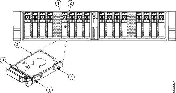
Drive Replacement Procedure
To replace or install a hot-pluggable hard drive, follow these steps:
Tip![]() You do not have to shut down or power off the server to replace hard drives or solid state drives (SSDs) because they are hot pluggable.
You do not have to shut down or power off the server to replace hard drives or solid state drives (SSDs) because they are hot pluggable.
Step 1![]() Remove the drive that you are replacing or remove a blank panel from an empty bay:
Remove the drive that you are replacing or remove a blank panel from an empty bay:
a.![]() Press the release button on the face of the drive tray. See Figure 3-7.
Press the release button on the face of the drive tray. See Figure 3-7.
b.![]() Grasp and open the ejector lever and then pull the drive tray out of the slot.
Grasp and open the ejector lever and then pull the drive tray out of the slot.
c.![]() If you are replacing an existing drive, remove the four drive tray screws that secure the drive to the tray and then lift the drive out of the tray.
If you are replacing an existing drive, remove the four drive tray screws that secure the drive to the tray and then lift the drive out of the tray.
a.![]() Place a new drive in the empty drive tray and replace the four drive tray screws.
Place a new drive in the empty drive tray and replace the four drive tray screws.
b.![]() With the ejector lever on the drive tray open, insert the drive tray into the empty drive bay.
With the ejector lever on the drive tray open, insert the drive tray into the empty drive bay.
c.![]() Push the tray into the slot until it touches the backplane, then close the ejector lever to lock the drive in place.
Push the tray into the slot until it touches the backplane, then close the ejector lever to lock the drive in place.
Figure 3-7 Removing and Replacing Hard Drives
|
|
|
||
|
|
|
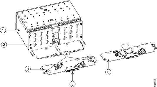
Replacing a Modular Drive Bay Assembly
This server allows modular configuration of the drive bays, so that you can use one or two drive bays depending on your needs.
Each drive bay assembly includes the chassis-steel drive bay, the attached drive backplane, and a transition card (expander or nonexpander version) that provides connection to your RAID controllers and the motherboard.
- Each of the two modular chassis drive bays can hold up to eight 2.5-inch drives.
- Each drive backplane connects to one transition card. The transition card connects the drive backplane to the motherboard and connects to cables from your RAID controller.
- The transition card is available in two versions:
–![]() Nonexpander—Two internal connections to the RAID controller card are required to control eight drives. This version includes two connectors for the cables from your RAID controller. One of the connectors allows control of drives 1 through 4 on the backplane. The other connector allows control of drives 5 through 8 on the backplane.
Nonexpander—Two internal connections to the RAID controller card are required to control eight drives. This version includes two connectors for the cables from your RAID controller. One of the connectors allows control of drives 1 through 4 on the backplane. The other connector allows control of drives 5 through 8 on the backplane.
–![]() Expander—One internal connection to the RAID controller card is required to control eight drives. This one connectors allows control of drives 1 through 8 on the backplane.
Expander—One internal connection to the RAID controller card is required to control eight drives. This one connectors allows control of drives 1 through 8 on the backplane.
- To use more than eight 2.5-inch drives in the server (up to 16), two drive bay modules are required, each with its own backplane and transition card.
Figure 3-8 Drive Bay Assembly and Transition Card (Two Versions)
|
|
|
||
|
|
|
||
|
|
|
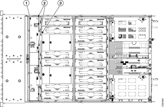
To install or replace the modular drive bay assembly, follow these steps:
Step 1![]() Remove the assembly that you are replacing. See Figure 3-8 and Figure 3-9:
Remove the assembly that you are replacing. See Figure 3-8 and Figure 3-9:
a.![]() Power off the server as described in the “Shutting Down and Powering Off the Server” section.
Power off the server as described in the “Shutting Down and Powering Off the Server” section.
b.![]() Slide the server out the front of the rack far enough so that you can remove the top cover. You might have to detach cables from the rear panel to provide clearance.
Slide the server out the front of the rack far enough so that you can remove the top cover. You might have to detach cables from the rear panel to provide clearance.
c.![]() Remove the top cover as described in “Removing and Replacing the Server Top Cover” section.
Remove the top cover as described in “Removing and Replacing the Server Top Cover” section.
d.![]() Remove all drives from the drive-bay module that you are replacing.
Remove all drives from the drive-bay module that you are replacing.
e.![]() Remove all memory risers from the front memory compartment (see Figure 3-9).
Remove all memory risers from the front memory compartment (see Figure 3-9).
Lift on the blue plastic handle on the top panel of the riser to disengage the latches at each end, and then pull the riser from its motherboard socket. See Replacing Memory Risers for more information.
Tip When you remove the memory risers, set them on an anti-static mat in the same order that they were removed. This will help you keep the same matched pairs of risers (as required) when you reinstall them.
f.![]() Remove the fan tray from the chassis, as described in Replacing a Fan Tray. You do not have to remove the fan modules from the fan tray.
Remove the fan tray from the chassis, as described in Replacing a Fan Tray. You do not have to remove the fan modules from the fan tray.
g.![]() Disconnect RAID controller cables from the transition card that you are replacing.
Disconnect RAID controller cables from the transition card that you are replacing.
Tip Label the cables before you disconnect them to aid replacement.
h.![]() Use a Number 1 Phillips-head screwdriver to remove the two screws that secure the transition card to the chassis floor (see Figure 3-9).
Use a Number 1 Phillips-head screwdriver to remove the two screws that secure the transition card to the chassis floor (see Figure 3-9).
i.![]() Slide the drive bay with attached backplane and transition card out the front of the chassis. The transition card disengages from its motherboard connector.
Slide the drive bay with attached backplane and transition card out the front of the chassis. The transition card disengages from its motherboard connector.

Note![]() Tilt the module downward as you slide it out the chassis opening to provide clearance over an alignment peg on the chassis floor.
Tilt the module downward as you slide it out the chassis opening to provide clearance over an alignment peg on the chassis floor.
Step 2![]() Install a new drive bay assembly:
Install a new drive bay assembly:
a.![]() Carefully slide the drive bay with attached backplane and transition card into the front chassis opening.
Carefully slide the drive bay with attached backplane and transition card into the front chassis opening.
Stop when the connector on the rear edge of the transition card is fully engaged with the motherboard connector and the front of the drive bay is even with the chassis front panel.
b.![]() Replace the two screws that secure the transition card to the chassis floor.
Replace the two screws that secure the transition card to the chassis floor.
c.![]() Replace the RAID controller cables to the connectors on the transition card.
Replace the RAID controller cables to the connectors on the transition card.
d.![]() Replace the fan tray as described in Replacing a Fan Tray.
Replace the fan tray as described in Replacing a Fan Tray.
e.![]() Replace all memory risers to the front compartment.
Replace all memory risers to the front compartment.
Use the alignment keys in the motherboard sockets to orient the risers correctly.
g.![]() Replace the server in the rack, replace cables, and then power on the server by pressing the Power button.
Replace the server in the rack, replace cables, and then power on the server by pressing the Power button.
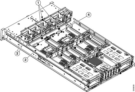
Figure 3-9 Removing and Replacing the Drive-Bay Module, Backplane, and Transition Card
|
|
Transition card on chassis floor |
|
|
|
|
|
Replacing Fan Modules
The six fan modules in the server are numbered as follows when you are facing the front of the server.
Figure 3-10 Fan Module Numbering
Tip![]() Each fan module has a fault LED that lights amber if the fan module fails.
Each fan module has a fault LED that lights amber if the fan module fails.
To replace or install a hot-pluggable fan module, follow these steps:
Step 1![]() Remove the fan module that you are replacing (see Figure 3-11):
Remove the fan module that you are replacing (see Figure 3-11):
a.![]() Slide the server out the front of the rack far enough so that you can remove the top cover. You might have to detach cables from the rear panel to provide clearance.
Slide the server out the front of the rack far enough so that you can remove the top cover. You might have to detach cables from the rear panel to provide clearance.
b.![]() Remove the top cover as described in “Removing and Replacing the Server Top Cover” section.
Remove the top cover as described in “Removing and Replacing the Server Top Cover” section.
c.![]() Insert your thumb and forefinger into the two release latches on the top of the fan module.
Insert your thumb and forefinger into the two release latches on the top of the fan module.
d.![]() Squeeze the release latches together and lift out the fan module.
Squeeze the release latches together and lift out the fan module.
Step 2![]() Install a new fan module:
Install a new fan module:
a.![]() Grasp the fan module by the release latches and align it with the empty fan bay and the connector on the floor of the fan tray. See Figure 3-11.
Grasp the fan module by the release latches and align it with the empty fan bay and the connector on the floor of the fan tray. See Figure 3-11.
b.![]() Press down on the top corners of the fan module until the connector is fully seated and the release latches lock in place.
Press down on the top corners of the fan module until the connector is fully seated and the release latches lock in place.
d.![]() Replace the server in the rack.
Replace the server in the rack.
Figure 3-11 Removing and Replacing Fan Modules
|
|
|
||
|
|
|
Replacing a Fan Tray
To replace a fan tray, follow these steps:
Step 1![]() Remove the fan tray that you are replacing (see Figure 3-12):
Remove the fan tray that you are replacing (see Figure 3-12):
a.![]() Power off the server as described in the “Shutting Down and Powering Off the Server” section.
Power off the server as described in the “Shutting Down and Powering Off the Server” section.
b.![]() Slide the server out the front of the rack far enough so that you can remove the top cover. You might have to detach cables from the rear panel to provide clearance.
Slide the server out the front of the rack far enough so that you can remove the top cover. You might have to detach cables from the rear panel to provide clearance.
c.![]() Remove the top cover as described in “Removing and Replacing the Server Top Cover” section.
Remove the top cover as described in “Removing and Replacing the Server Top Cover” section.
d.![]() Remove all memory risers from the front compartment to provide clearance.
Remove all memory risers from the front compartment to provide clearance.
Tip Note the locations of the memory risers before you remove them to assist you in replacing them.
e.![]() Use a Number 1 Phillips-head screwdriver to loosen the three captive thumbscrews that secure the fan tray to the chassis.
Use a Number 1 Phillips-head screwdriver to loosen the three captive thumbscrews that secure the fan tray to the chassis.
f.![]() Lift the fan tray straight up and out of the chassis.
Lift the fan tray straight up and out of the chassis.
Step 2![]() Install a new fan tray (see Figure 3-12):
Install a new fan tray (see Figure 3-12):
a.![]() Carefully align the new tray with the chassis and lower it in place:
Carefully align the new tray with the chassis and lower it in place:
–![]() Align the connector on the underside of the tray with its socket on the motherboard.
Align the connector on the underside of the tray with its socket on the motherboard.
–![]() Align the two guide pegs on each end of the tray with the slots in the chassis.
Align the two guide pegs on each end of the tray with the slots in the chassis.
b.![]() Use a Number 1 Phillips-head screwdriver to tighten the three captive thumbscrews that secure the tray to the motherboard and chassis.
Use a Number 1 Phillips-head screwdriver to tighten the three captive thumbscrews that secure the tray to the motherboard and chassis.
c.![]() Replace the memory risers that you removed. Be sure to observe the configuration rules as described in Memory Riser Population Guidelines.
Replace the memory risers that you removed. Be sure to observe the configuration rules as described in Memory Riser Population Guidelines.
e.![]() Replace the server in the rack, replace cables, and then power on the server by pressing the Power button.
Replace the server in the rack, replace cables, and then power on the server by pressing the Power button.
Figure 3-12 Removing and Replacing a Fan Tray
|
|
|
||
|
|
|
Replacing Memory Risers
This section describes how to remove and replace memory risers. For information about replacing DIMMs on the memory risers, see Replacing DIMMs.
This section includes the following topics:
- Memory Riser Population Guidelines
- Identifying a Faulty Memory Riser or DIMM
- Memory Riser Replacement Procedure
The memory risers connect to motherboard sockets. There are two versions of memory riser available for use in this server:
Memory Riser Population Guidelines
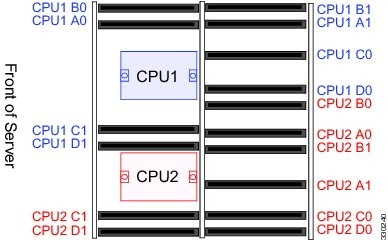
Figure 3-13 shows the CPUs and memory riser sockets on the motherboard.
Each CPU controls eight Millbrook-2 DDR3 channels. There is one memory riser for each DDR3 channel.
Use the following population guidelines when installing or replacing memory risers:
- The server must have either all two-DIMM risers or all four-DIMM risers. Do not mix riser types.
- Memory risers must be installed in pairs on paired DDR3 channels. The paired channels are as follows:
–![]() CPU1— [A0:A1], [B0:B1], [C0:C1], [D0:D1]
CPU1— [A0:A1], [B0:B1], [C0:C1], [D0:D1]
–![]() CPU2— [A0:A1], [B0:B1], [C0:C1], [D0:D1]
CPU2— [A0:A1], [B0:B1], [C0:C1], [D0:D1]
For example, the DIMM configurations must be identical on risers in A0:A1; however, the A0:A1 configurations do not have to be identical with the B0:B1 configurations.
- The minimum riser configuration is one matched pair of risers on either CPU1 or CPU2. Either CPU can boot and run from a single matched pair of risers.
- Any riser installed on a socket that is controlled by an absent CPU is not recognized.
- Although it is not required, for optimal performance distribute riser pairs evenly across the CPUs. Follow this recommended installation order (see Figure 3-13):
1. CPU1 [A0:A1] and CPU2 [A0:A1]
2. CPU1 [C0:C1] and CPU2 [C0:C1]
3. CPU1 [B0:B1] and CPU2 [B0:B1]
4. CPU1 [D0:D1] and CPU2 [D0:D1]
Figure 3-13 Memory Riser Sockets on Motherboard
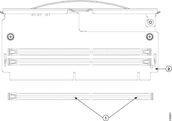
Identifying a Faulty Memory Riser or DIMM
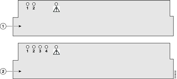
The memory riser includes fault LEDs on its top panel so that you can identify which riser is faulty or which riser contains faulty DIMMs (see Figure 3-14).
- If one or more of the numbered DIMM fault LEDs are lit, replace the corresponding DIMMs as described in Replacing DIMMs.
- If the riser fault LED is lit, replace the memory riser as described in Memory Riser Replacement Procedure.
Figure 3-14 Memory Riser Fault LEDs
|
|
|
Memory Riser Replacement Procedure
To replace or install a memory riser, follow these steps:
Step 1![]() Remove the memory riser that you are replacing: See Figure 3-15:
Remove the memory riser that you are replacing: See Figure 3-15:
a.![]() Power off the server as described in the “Shutting Down and Powering Off the Server” section.
Power off the server as described in the “Shutting Down and Powering Off the Server” section.
b.![]() Slide the server out the front of the rack far enough so that you can remove the top cover. You might have to detach cables from the rear panel to provide clearance.
Slide the server out the front of the rack far enough so that you can remove the top cover. You might have to detach cables from the rear panel to provide clearance.
c.![]() Remove the top cover as described in “Removing and Replacing the Server Top Cover” section.
Remove the top cover as described in “Removing and Replacing the Server Top Cover” section.
d.![]() Lift on the blue plastic handle on the top panel of the riser to disengage the latches at each end, and then pull the riser from the motherboard socket.
Lift on the blue plastic handle on the top panel of the riser to disengage the latches at each end, and then pull the riser from the motherboard socket.
The blue plastic handle is the release mechanism.
e.![]() If you are installing or replacing DIMMs on the memory riser, use the instructions in Replacing DIMMs.
If you are installing or replacing DIMMs on the memory riser, use the instructions in Replacing DIMMs.
Step 2![]() Install a new memory riser:
Install a new memory riser:
Note![]() Before installing memory risers or DIMMs, refer to the population guidelines. See Memory Riser Population Guidelines and DIMM Performance Guidelines and Population Rules.
Before installing memory risers or DIMMs, refer to the population guidelines. See Memory Riser Population Guidelines and DIMM Performance Guidelines and Population Rules.
a.![]() Align the riser with the empty motherboard connector.
Align the riser with the empty motherboard connector.
Note![]() The risers face in alternating directions. Use the alignment keys in the motherboard socket to orient the riser correctly. See Figure 3-15.
The risers face in alternating directions. Use the alignment keys in the motherboard socket to orient the riser correctly. See Figure 3-15.
b.![]() Simultaneously press down on both top corners of the riser top panel to ensure that it is properly seated in the motherboard connector. Keep the riser vertical without tilting it at an angle.
Simultaneously press down on both top corners of the riser top panel to ensure that it is properly seated in the motherboard connector. Keep the riser vertical without tilting it at an angle.
d.![]() Replace the server in the rack, replace cables, and then power on the server by pressing the Power button.
Replace the server in the rack, replace cables, and then power on the server by pressing the Power button.
Figure 3-15 Removing and Replacing Memory Risers
|
|
|
Replacing DIMMs
This section includes the following topics:
Note![]() To ensure the best server performance, it is important that you are familiar with memory performance guidelines and population rules before you install or replace memory.
To ensure the best server performance, it is important that you are familiar with memory performance guidelines and population rules before you install or replace memory.
DIMM Performance Guidelines and Population Rules
This section describes the type of memory that the server requires and its effect on performance. The section includes the following topics:
DIMM Sockets
Figure 3-16 shows the numbering of the DIMM slots on the two types of memory risers.
Figure 3-16 DIMM Slots on Memory Risers
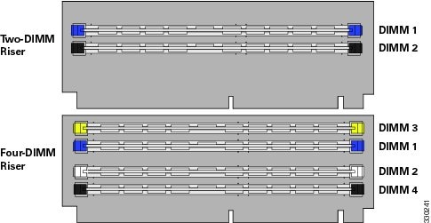
DIMM Population Rules
Observe the following guidelines when installing or replacing DIMMs:
- The minimum memory riser configuration is one matched pair of memory risers on either CPU1 or CPU2. See Replacing Memory Risers for more detail on memory riser population.
- Matched pairs of risers on paired DDR3 channels must have identical DIMM configurations.
For example, the DIMM configurations must be identical on risers in A0:A1; however, the A0:A1 configurations do not have to be identical with the B0:B1 configurations.
- Any DIMM installed in a memory riser corresponding to an empty CPU slot becomes inaccessible.
- Two-DIMM memory riser population rules are as follows:
–![]() The two-DIMM riser can operate with one or two DIMMs installed.
The two-DIMM riser can operate with one or two DIMMs installed.
–![]() Both DIMMs installed on any one riser must be identical.
Both DIMMs installed on any one riser must be identical.
–![]() Populate the slots in this order: 1, 2. See Figure 3-16.
Populate the slots in this order: 1, 2. See Figure 3-16.
–![]() The four-DIMM riser can operate with one, two, three, or four DIMMs installed.
The four-DIMM riser can operate with one, two, three, or four DIMMs installed.
–![]() All DIMMs installed on any one riser must be identical.
All DIMMs installed on any one riser must be identical.
–![]() Populate the slots in this order: 1, 2, 3, 4. See Figure 3-16.
Populate the slots in this order: 1, 2, 3, 4. See Figure 3-16.
DIMM Sparing and Rank Sparing
DIMM and rank sparing can be enabled in the BIOS configuration utility.
Sparing involves utilizing one of the DIMM pairs or rank pairs within each memory riser as a spare unit. When any of the other DIMM pairs within the same memory riser experiences errors beyond a pre-defined threshold, it fails over to the spare DIMM pair. Spared DIMMs and ranks are hidden from the user and the OS so that the BIOS can migrate to a spare unit when it finds degrading DIMMs.
When sparing is enabled, the available system memory is lesser than the total installed memory.
DIMM Replacement Procedure
Identifying a Faulty Memory Riser or DIMM
The memory riser includes fault LEDs on its top panel so that you can identify which riser is faulty or which riser contains faulty DIMMs (see Figure 3-14).
- If one or more of the numbered DIMM fault LEDs are lit, replace the corresponding DIMMs as described in Replacing DIMMs. See Figure 3-16 for the DIMM slot numbering on the riser.
- If the riser fault LED is lit, replace the memory riser as described in Memory Riser Replacement Procedure.
Replacing DIMMs
To install a DIMM assembly, follow these steps:
Step 1![]() Remove the DIMMs that you are replacing:
Remove the DIMMs that you are replacing:
a.![]() Power off the server as described in the “Shutting Down and Powering Off the Server” section.
Power off the server as described in the “Shutting Down and Powering Off the Server” section.
b.![]() Slide the server out the front of the rack far enough so that you can remove the top cover. You might have to detach cables from the rear panel to provide clearance.
Slide the server out the front of the rack far enough so that you can remove the top cover. You might have to detach cables from the rear panel to provide clearance.
c.![]() Remove the top cover as described in “Removing and Replacing the Server Top Cover” section.
Remove the top cover as described in “Removing and Replacing the Server Top Cover” section.
d.![]() Identify the memory riser that contains the faulty DIMM. See Identifying a Faulty Memory Riser or DIMM.
Identify the memory riser that contains the faulty DIMM. See Identifying a Faulty Memory Riser or DIMM.
e.![]() Lift on the blue plastic handle on the top panel of the riser to disengage the latches at each end, and then pull the riser from the motherboard socket.
Lift on the blue plastic handle on the top panel of the riser to disengage the latches at each end, and then pull the riser from the motherboard socket.
f.![]() Locate the faulty DIMM and remove it from the socket on the memory riser by opening the ejector levers at both ends of the DIMM socket.
Locate the faulty DIMM and remove it from the socket on the memory riser by opening the ejector levers at both ends of the DIMM socket.
Note![]() Before installing risers or DIMMs, refer to the population guidelines. See Memory Riser Population Guidelines and DIMM Performance Guidelines and Population Rules.
Before installing risers or DIMMs, refer to the population guidelines. See Memory Riser Population Guidelines and DIMM Performance Guidelines and Population Rules.
a.![]() Align the new DIMM with the socket on the memory riser. Use the alignment key in the DIMM socket to correctly orient the DIMM.
Align the new DIMM with the socket on the memory riser. Use the alignment key in the DIMM socket to correctly orient the DIMM.
b.![]() Push the DIMM into the connector until it is fully seated and the ejector levers on either side of the connector lock into place.
Push the DIMM into the connector until it is fully seated and the ejector levers on either side of the connector lock into place.
c.![]() Align the memory riser with the empty motherboard connector.
Align the memory riser with the empty motherboard connector.
Note![]() Memory risers face in alternating directions. Use the alignment keys in the motherboard socket to orient the riser correctly. See Figure 3-15.
Memory risers face in alternating directions. Use the alignment keys in the motherboard socket to orient the riser correctly. See Figure 3-15.
d.![]() Simultaneously press down on both top corners of the riser to ensure that it is properly seated in the motherboard connector. Keep the riser vertical without tilting it at an angle.
Simultaneously press down on both top corners of the riser to ensure that it is properly seated in the motherboard connector. Keep the riser vertical without tilting it at an angle.
f.![]() Replace the server in the rack, replace cables, and then power on the server by pressing the Power button.
Replace the server in the rack, replace cables, and then power on the server by pressing the Power button.
Replacing CPUs and Heatsinks
This server has two CPUs. Each CPU supports eight memory risers connected by serial memory interface (SMI). See Figure 3-17.
Figure 3-17 CPUs and Memory Riser Sockets
Additional CPU-Related Parts To Order With RMA Replacement Motherboards
When a return material authorization (RMA) of the motherboard or CPU is done on a Cisco UCS C-series server, there are additional parts that might not be included with the CPU or motherboard spare bill of materials (BOM). The TAC engineer might need to add the additional parts to the RMA to help ensure a successful replacement.
–![]() Heat sink cleaning kit (UCSX-HSCK=)
Heat sink cleaning kit (UCSX-HSCK=)
–![]() Thermal grease kit for C260 (UCS-CPU-GREASE=)
Thermal grease kit for C260 (UCS-CPU-GREASE=)
–![]() Heat sink (UCSC-HS-01-C260=)
Heat sink (UCSC-HS-01-C260=)
–![]() Heat sink cleaning kit (UCSX-HSCK=)
Heat sink cleaning kit (UCSX-HSCK=)
A CPU heatsink cleaning kit is good for up to four CPU and heatsink cleanings. The cleaning kit contains two bottles of solution, one to clean the CPU and heatsink of old thermal interface material and the other to prepare the surface of the heatsink.
New heatsink spares have preinstalled thermal interface material covered by a small sheet of plastic. It is important to clean the old thermal interface material off of the CPU prior to installing the heatsinks. Therefore, when ordering new heatsinks it is still necessary to order the heatsink cleaning kit at a minimum.
CPU replacement Procedure
To install or replace a CPU heatsink and CPU, follow these steps:
Step 1![]() Remove the CPU and heatsink that you are replacing:
Remove the CPU and heatsink that you are replacing:
a.![]() Power off the server as described in the “Shutting Down and Powering Off the Server” section.
Power off the server as described in the “Shutting Down and Powering Off the Server” section.
b.![]() Slide the server out the front of the rack far enough so that you can remove the top cover. You might have to detach cables from the rear panel to provide clearance.
Slide the server out the front of the rack far enough so that you can remove the top cover. You might have to detach cables from the rear panel to provide clearance.
c.![]() Remove the top cover as described in “Removing and Replacing the Server Top Cover” section.
Remove the top cover as described in “Removing and Replacing the Server Top Cover” section.
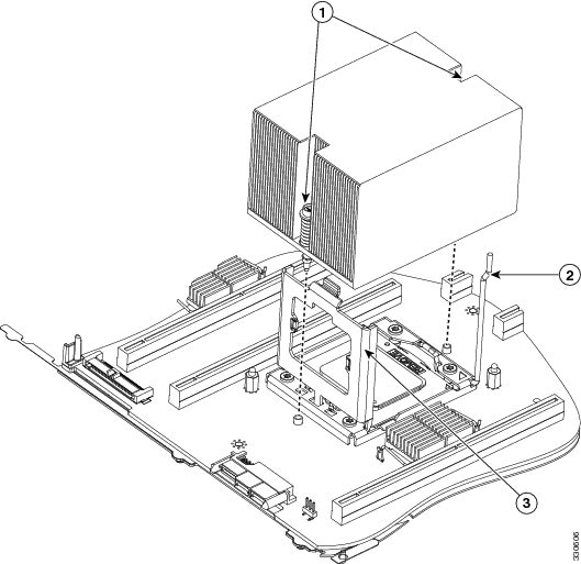
d.![]() Use a Number 2 Phillips-head screwdriver to loosen the two captive screws that secure the heatsink and lift it off of the CPU. See Figure 3-18.
Use a Number 2 Phillips-head screwdriver to loosen the two captive screws that secure the heatsink and lift it off of the CPU. See Figure 3-18.
Note![]() Alternate loosening each screw evenly to avoid damaging the heatsink or CPU.
Alternate loosening each screw evenly to avoid damaging the heatsink or CPU.
e.![]() Unclip the CPU retaining latch and open the hinged the CPU cover plate. See Figure 3-18.
Unclip the CPU retaining latch and open the hinged the CPU cover plate. See Figure 3-18.
f.![]() Lift the CPU out of the socket and set it aside on an antistatic mat or in an antistatic bag.
Lift the CPU out of the socket and set it aside on an antistatic mat or in an antistatic bag.
Figure 3-18 CPU Latching Mechanism
|
|
|
||
|
|
|
a.![]() Insert the replacement CPU in the socket.
Insert the replacement CPU in the socket.
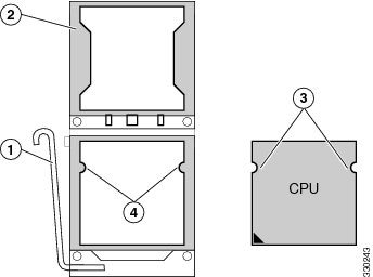
Note![]() Orient the CPU alignment notches with the alignment keys in the socket. See Figure 3-19.
Orient the CPU alignment notches with the alignment keys in the socket. See Figure 3-19.
b.![]() Close the CPU cover plate and clip down the CPU retaining latch.
Close the CPU cover plate and clip down the CPU retaining latch.
Figure 3-19 CPU Socket Alignment Keys
|
|
|
||
|
|
|
a.![]() Apply an alcohol-based cleaning solution to the old thermal pad and let it soak for a least 15 seconds.
Apply an alcohol-based cleaning solution to the old thermal pad and let it soak for a least 15 seconds.
b.![]() Wipe all of the old thermal pad off the heatsink using a soft cloth that will not scratch the heatsink surface.
Wipe all of the old thermal pad off the heatsink using a soft cloth that will not scratch the heatsink surface.
c.![]() Peel the protective film from the thermal pad that is on the bottom of the new heatsink.
Peel the protective film from the thermal pad that is on the bottom of the new heatsink.
d.![]() Align the heatsink captive screws with the motherboard standoffs, then use a Number 2 Phillips-head screwdriver to tighten the captive screws evenly until the screws stop against the captive springs.
Align the heatsink captive screws with the motherboard standoffs, then use a Number 2 Phillips-head screwdriver to tighten the captive screws evenly until the screws stop against the captive springs.
Note![]() Alternate tightening each screw evenly to avoid damaging the heatsink or CPU.
Alternate tightening each screw evenly to avoid damaging the heatsink or CPU.
f.![]() Replace the server in the rack, replace cables, and then power on the server by pressing the Power button.
Replace the server in the rack, replace cables, and then power on the server by pressing the Power button.
Replacing the Motherboard RTC Battery
Warning![]() There is danger of explosion if the battery is replaced incorrectly. Replace the battery only with the same or equivalent type recommended by the manufacturer. Dispose of used batteries according to the manufacturer’s instructions. [Statement 1015]
There is danger of explosion if the battery is replaced incorrectly. Replace the battery only with the same or equivalent type recommended by the manufacturer. Dispose of used batteries according to the manufacturer’s instructions. [Statement 1015]
The CMOS real-time clock (RTC) battery retains system settings when the server is disconnected from power. The battery type is Panasonic CR2032 or equivalent.
To replace or install the motherboard CMOS battery, follow these steps:
Step 1![]() Remove the CMOS battery (see Figure 3-20):
Remove the CMOS battery (see Figure 3-20):
a.![]() Power off the server as described in the “Shutting Down and Powering Off the Server” section.
Power off the server as described in the “Shutting Down and Powering Off the Server” section.
b.![]() Slide the server out the front of the rack far enough so that you can remove the top cover. You might have to detach cables from the rear panel to provide clearance.
Slide the server out the front of the rack far enough so that you can remove the top cover. You might have to detach cables from the rear panel to provide clearance.
c.![]() Remove the top cover as described in “Removing and Replacing the Server Top Cover” section.
Remove the top cover as described in “Removing and Replacing the Server Top Cover” section.
d.![]() Locate the CMOS battery. See Figure 3-20.
Locate the CMOS battery. See Figure 3-20.
e.![]() Bend the battery retaining clip away from the battery and use a pair of needle-nose pliers to pull the battery from the socket.
Bend the battery retaining clip away from the battery and use a pair of needle-nose pliers to pull the battery from the socket.
Step 2![]() Install a CMOS battery:
Install a CMOS battery:
a.![]() Bend the retaining clip away from the battery socket and insert the battery in the socket.
Bend the retaining clip away from the battery socket and insert the battery in the socket.
Note![]() The positive side of the battery marked “3V+” should face the retaining clip.
The positive side of the battery marked “3V+” should face the retaining clip.
b.![]() Push the battery into the socket until it is fully seated.
Push the battery into the socket until it is fully seated.
Note![]() Ensure that the retaining clip clicks over the top of the battery.
Ensure that the retaining clip clicks over the top of the battery.
d.![]() Replace the server in the rack, replace cables, and then power on the server by pressing the Power button.
Replace the server in the rack, replace cables, and then power on the server by pressing the Power button.
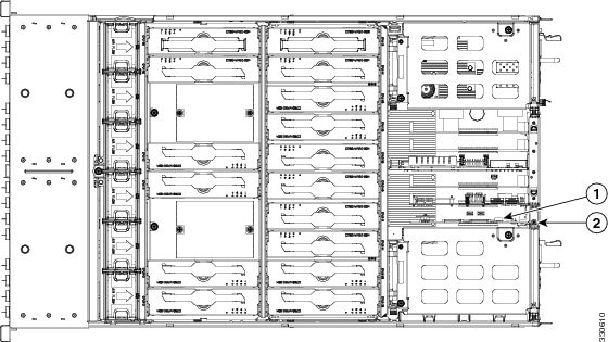
Figure 3-20 Removing and Replacing the Motherboard RTC Battery
|
|
|
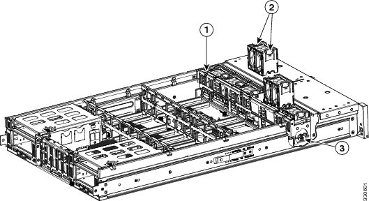
Replacing a PCIe Riser Assembly
The server contains two PCIe risers for horizontal installation of PCIe cards. These risers wrap around the power supply bays and connect to dedicated PCIe slots 1 and 7 on the motherboard. These risers each provide one standard-profile, half-length, x16 horizontal slot.
To install or replace a PCIe riser assembly, follow these steps:
Step 1![]() Remove the PCIe riser assembly that you are replacing (see Figure 3-21):
Remove the PCIe riser assembly that you are replacing (see Figure 3-21):
a.![]() Power off the server as described in the “Shutting Down and Powering Off the Server” section.
Power off the server as described in the “Shutting Down and Powering Off the Server” section.
b.![]() Slide the server out the front of the rack far enough so that you can remove the top cover. You might have to detach cables from the rear panel to provide clearance.
Slide the server out the front of the rack far enough so that you can remove the top cover. You might have to detach cables from the rear panel to provide clearance.
c.![]() Remove the top cover as described in “Removing and Replacing the Server Top Cover” section.
Remove the top cover as described in “Removing and Replacing the Server Top Cover” section.
d.![]() Use a Number 2 Phillips-head screwdriver to loosen the two captive thumbscrews that secure the PCIe riser assembly.
Use a Number 2 Phillips-head screwdriver to loosen the two captive thumbscrews that secure the PCIe riser assembly.
e.![]() Lift straight up on both ends of the PCIe riser assembly to disengage its circuit board from the socket on the motherboard.
Lift straight up on both ends of the PCIe riser assembly to disengage its circuit board from the socket on the motherboard.
Step 2![]() Install a new PCIe riser assembly.
Install a new PCIe riser assembly.
a.![]() Set the PCIe riser assembly back in place over the power supply bay.
Set the PCIe riser assembly back in place over the power supply bay.
b.![]() Align the circuit board edge with the socket on the motherboard and then push straight down on both ends of the assembly to fully engage the board with the socket.
Align the circuit board edge with the socket on the motherboard and then push straight down on both ends of the assembly to fully engage the board with the socket.
c.![]() Tighten the two captive thumbscrews that secure the riser assembly in place.
Tighten the two captive thumbscrews that secure the riser assembly in place.
e.![]() Replace the server in the rack, replace cables, and then power on the server by pressing the Power button.
Replace the server in the rack, replace cables, and then power on the server by pressing the Power button.
Figure 3-21 Removing and Replacing the PCIe Riser Assembly
|
|
|
||
|
|
|
Replacing an I/O Riser
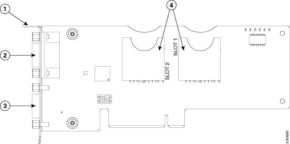
The I/O riser is a modular PCIe form-factor card that has a designated motherboard socket inside the server (see Figure 3-23). The module provides the external VGA video and RS-232 serial connectors for the rear panel of the server. See Figure 3-22.
The I/O riser also provides two internal slots for Cisco FlexFlash cards. For more information about Cisco FlexFlash cards, see Replacing a Cisco Flexible Flash Drive.
Figure 3-22 I/O Riser, Including Cisco FlexFlash Slots
|
|
|
||
|
|
|
To install or replace an I/O riser, follow these steps:
Step 1![]() Remove the I/O riser that you are replacing (see Figure 3-23):
Remove the I/O riser that you are replacing (see Figure 3-23):
a.![]() Power off the server as described in the “Shutting Down and Powering Off the Server” section.
Power off the server as described in the “Shutting Down and Powering Off the Server” section.
b.![]() Slide the server out the front of the rack far enough so that you can remove the top cover. You might have to detach cables from the rear panel to provide clearance.
Slide the server out the front of the rack far enough so that you can remove the top cover. You might have to detach cables from the rear panel to provide clearance.
c.![]() Remove the top cover as described in “Removing and Replacing the Server Top Cover” section.
Remove the top cover as described in “Removing and Replacing the Server Top Cover” section.
d.![]() Disconnect any external cables from the I/O riser ports.
Disconnect any external cables from the I/O riser ports.
e.![]() Use a Number 1 Phillips-head screwdriver to remove the single screw that secures the I/O riser rear panel tab to the chassis.
Use a Number 1 Phillips-head screwdriver to remove the single screw that secures the I/O riser rear panel tab to the chassis.
f.![]() Lift the I/O riser straight up from the motherboard connector.
Lift the I/O riser straight up from the motherboard connector.
Note![]() Lift up on both ends of the I/O riser evenly to avoid damaging its connector.
Lift up on both ends of the I/O riser evenly to avoid damaging its connector.
Step 2![]() Install a new I/O riser:
Install a new I/O riser:
a.![]() Align the new I/O riser with its empty designated socket on the motherboard. See Figure 3-23.
Align the new I/O riser with its empty designated socket on the motherboard. See Figure 3-23.
Note![]() You must install the I/O riser in its designated motherboard socket.
You must install the I/O riser in its designated motherboard socket.
b.![]() Push down evenly on both ends of the I/O riser until it is fully seated in its motherboard socket.
Push down evenly on both ends of the I/O riser until it is fully seated in its motherboard socket.
c.![]() Ensure that the I/O riser rear panel tab sits flat against the chassis rear panel opening.
Ensure that the I/O riser rear panel tab sits flat against the chassis rear panel opening.
d.![]() Install the single screw that secures the I/O riser to the chassis.
Install the single screw that secures the I/O riser to the chassis.
f.![]() Replace the server in the rack, replace cables, and then power on the server by pressing the Power button.
Replace the server in the rack, replace cables, and then power on the server by pressing the Power button.
Figure 3-23 Removing and Replacing an I/O Riser
|
|
|
Replacing a Cisco Flexible Flash Drive
Overview of the Pre-Installed Cisco FlexFlash Drive
This server is shipped from the factory with one pre-installed Cisco FlexFlash drive. The slots for these drives are on the I/O riser (see Replacing an I/O Riser).
Note![]() To use dual FlexFlash drives, your server must have minimum CIMC/BIOS 1.5(1) or later installed.
To use dual FlexFlash drives, your server must have minimum CIMC/BIOS 1.5(1) or later installed.
The Cisco FlexFlash drive is pre-installed with three software bundles, each on one of four preconfigured virtual drives (VDs). The fourth VD allows you to install an OS or embedded hypervisor.
The VDs are configured as follows:
1.![]() Cisco UCS Server Configuration Utility (SCU).
Cisco UCS Server Configuration Utility (SCU).
2.![]() Hypervisor (HV). This is a VD that you can use for your own purposes.
Hypervisor (HV). This is a VD that you can use for your own purposes.
Enabling a Cisco FlexFlash Virtual Drive
Each of the VDs on the pre-installed Cisco FlexFlash drive can be separately enabled or hidden from the host. The default as shipped from the factory is for all VDs to be hidden.
To enable VDs and expose them to the host, follow these steps:
Step 1![]() Log in to CIMC interface for the server, using the IP address of the server.
Log in to CIMC interface for the server, using the IP address of the server.
Step 2![]() Navigate through GUI tabs to Server > Inventory > Storage.
Navigate through GUI tabs to Server > Inventory > Storage.
Step 3![]() Click FlexFlash-0 in the Storage Adapters list.
Click FlexFlash-0 in the Storage Adapters list.
Step 4![]() Click on Configure Operational Profile in the Actions area.
Click on Configure Operational Profile in the Actions area.
The Operational Profile dialog opens.
Step 5![]() Check the box for each VD that you want to enable and expose to the host, then click Save Changes.
Check the box for each VD that you want to enable and expose to the host, then click Save Changes.
Booting a Cisco FlexFlash Virtual Drive
When you want to access the Cisco SCU or Cisco HUU software, you boot its VD with a one-time boot option. When you want to boot the hypervisor (HV) VD, you boot it with a permanent boot order selection. See the following topics in this section:
Booting the Cisco SCU and Cisco HUU Software VDs
You can access the preinstalled Cisco SCU and Cisco HUU software bundles on a Cisco FlexFlash drive by booting their respective VDs with a one-time boot option:
Step 1![]() Enable the SCU or HUU VD.
Enable the SCU or HUU VD.
See Enabling a Cisco FlexFlash Virtual Drive.
Step 2![]() In the CIMC GUI interface, navigate through the tabs to Server > BIOS.
In the CIMC GUI interface, navigate through the tabs to Server > BIOS.
Step 3![]() Click Configure Boot Override Priority.
Click Configure Boot Override Priority.
The Boot Override Priority dialog opens.
Step 4![]() Pull down the menu and select SCU or HUU, then click OK.
Pull down the menu and select SCU or HUU, then click OK.
The server boots the selected VD.
Note![]() This is a one-time boot option. After running Cisco SCU or Cisco HUU, the server returns to its previously configured boot path.
This is a one-time boot option. After running Cisco SCU or Cisco HUU, the server returns to its previously configured boot path.
Booting the Hypervisor VD
You can boot the hypervisor (HV) VD with a more permanent boot selection. (To change the boot order one time, use the procedure in Booting the Cisco SCU and Cisco HUU Software VDs.
To permanently set the boot order for an HV VD, use the following steps:
Step 1![]() Boot the server and watch for the prompt to press F2 to open the BIOS Setup utility.
Boot the server and watch for the prompt to press F2 to open the BIOS Setup utility.
Step 2![]() When prompted, press F2 to open the BIOS Setup utility.
When prompted, press F2 to open the BIOS Setup utility.
Step 3![]() Navigate to the Boot Options tab.
Navigate to the Boot Options tab.
Step 4![]() Use the Boot Options screen to set the HV VD to your desired boot order for the server.
Use the Boot Options screen to set the HV VD to your desired boot order for the server.
Monitoring and Managing a Cisco FlexFlash Drive
You can monitor and manage your installed Cisco FlexFlash drives by using the CIMC GUI interface or the CLI interface. See the Cisco UCS C-Series Rack-Mount Server Configuration Guide or the Cisco UCS C-Series Rack-Mount Server CLI Configuration Guide in the documentation roadmap linked below.
The links to these documents are in the C-Series documentation roadmap:
Synchronizing RAID After Installing a Second Cisco FlexFlash Drive
Note![]() To use dual FlexFlash drives, your server must have minimum CIMC/BIOS 1.5(1) or later installed.
To use dual FlexFlash drives, your server must have minimum CIMC/BIOS 1.5(1) or later installed.
After you install or replace a second Cisco FlexFlash drive, you must synchronize the RAID partition by using the Cisco UCS Server Configuration Utility (SCU).
The SCU provides an option to synchronize the Hypervisor VD, configured as a RAID-1 disk. This feature is available only when both Cisco FlexFlash drive slots are populated.
When one member slot of the SD card is corrupt, use this option to synchronize the hypervisor data across two members of the RAID-1 virtual disk. You can initiate this synchronization only if two cards are detected and the RAID-1 group is determined as unhealthy (one member is corrupt).
Step 1![]() Click the Hypervisor Sync icon on the toolbar of the SCU interface.
Click the Hypervisor Sync icon on the toolbar of the SCU interface.
A dialog prompts you to confirm that you want to synchronize the Hypervisor RAID.
A dialog is displayed when the synchronization is complete.
After you click OK, the Hypervisor Sync icon on the toolbar is greyed out.
For more information about the utility, see the Cisco UCS Server Configuration Utility User Guide.
Cisco FlexFlash Drive Replacement Procedure
To install or replace a Cisco FlexFlash drive, follow these steps:
Step 1![]() Remove the SD card that you are replacing. See Figure 3-23:
Remove the SD card that you are replacing. See Figure 3-23:
a.![]() Power off the server as described in the “Shutting Down and Powering Off the Server” section.
Power off the server as described in the “Shutting Down and Powering Off the Server” section.
b.![]() Slide the server out the front of the rack far enough so that you can remove the top cover. You might have to detach cables from the rear panel to provide clearance.
Slide the server out the front of the rack far enough so that you can remove the top cover. You might have to detach cables from the rear panel to provide clearance.
c.![]() Remove the top cover as described in “Removing and Replacing the Server Top Cover” section.
Remove the top cover as described in “Removing and Replacing the Server Top Cover” section.
d.![]() Locate the Cisco FlexFlash drive that you are replacing on the I/O riser card. See Figure 3-23.
Locate the Cisco FlexFlash drive that you are replacing on the I/O riser card. See Figure 3-23.
e.![]() Push down on the top of the Cisco FlexFlash drive, then release it to allow it to spring up in the socket.
Push down on the top of the Cisco FlexFlash drive, then release it to allow it to spring up in the socket.
f.![]() Remove the Cisco FlexFlash drive from the socket.
Remove the Cisco FlexFlash drive from the socket.
g.![]() Wait 10 seconds for the Cisco FlexFlash management software to recognize and react to the absence of the drive.
Wait 10 seconds for the Cisco FlexFlash management software to recognize and react to the absence of the drive.
Step 2![]() Install a Cisco FlexFlash drive:
Install a Cisco FlexFlash drive:
Note![]() To be usable for Cisco FlexFlash, an SD card must be at least 16 GB in size.
To be usable for Cisco FlexFlash, an SD card must be at least 16 GB in size.
Note![]() Any SD card that is installed into the Cisco FlexFlash slot is configured with the VD partitioning described in Overview of the Pre-Installed Cisco FlexFlash Drive. This overwrites data on the SD card where Cisco stores the configuration metadata.
Any SD card that is installed into the Cisco FlexFlash slot is configured with the VD partitioning described in Overview of the Pre-Installed Cisco FlexFlash Drive. This overwrites data on the SD card where Cisco stores the configuration metadata.
a.![]() Insert the Cisco FlexFlash drive into an SD card slot on the I/O riser with the label side facing outward.
Insert the Cisco FlexFlash drive into an SD card slot on the I/O riser with the label side facing outward.
b.![]() Press down on the top of the drive until it clicks in the slot and stays in place. The top of the drive is level with the top edge of the I/O riser when fully seated.
Press down on the top of the drive until it clicks in the slot and stays in place. The top of the drive is level with the top edge of the I/O riser when fully seated.
d.![]() Replace the server in the rack, replace cables, and then power on the server by pressing the Power button.
Replace the server in the rack, replace cables, and then power on the server by pressing the Power button.
Replacing a 10-Gb LOM Module
The 10-Gb LOM module is a modular PCIe form-factor card (UCSX-MLOM) that is supported only in PCIe slot 4 (see Figure 3-26). The module provides two external 10-Gb SFP+ connectors for the rear panel of the server.
To install or replace a 10-Gb LOM module, follow these steps:
Step 1![]() Remove the 10-Gb LOM module that you are replacing (see Figure 3-25):
Remove the 10-Gb LOM module that you are replacing (see Figure 3-25):
a.![]() Power off the server as described in the “Shutting Down and Powering Off the Server” section.
Power off the server as described in the “Shutting Down and Powering Off the Server” section.
b.![]() Slide the server out the front of the rack far enough so that you can remove the top cover. You might have to detach cables from the rear panel to provide clearance.
Slide the server out the front of the rack far enough so that you can remove the top cover. You might have to detach cables from the rear panel to provide clearance.
c.![]() Remove the top cover as described in “Removing and Replacing the Server Top Cover” section.
Remove the top cover as described in “Removing and Replacing the Server Top Cover” section.
d.![]() Open the hinged PCIe card retainer. Pinch the two release latches toward the center of the retainer while you lift up on the front edge of the retainer to open it (see Figure 3-24).
Open the hinged PCIe card retainer. Pinch the two release latches toward the center of the retainer while you lift up on the front edge of the retainer to open it (see Figure 3-24).
Figure 3-24 Hinged PCIe Card Retainer on Rear of Chassis
e.![]() Lift the module straight up from the motherboard socket.
Lift the module straight up from the motherboard socket.
Note![]() Lift up on both ends of the module evenly to avoid damaging its socket.
Lift up on both ends of the module evenly to avoid damaging its socket.
Step 2![]() Install a new 10-Gb LOM module:
Install a new 10-Gb LOM module:
a.![]() Align the new module with the empty PCIe slot 4 socket on the motherboard. See Figure 3-25.
Align the new module with the empty PCIe slot 4 socket on the motherboard. See Figure 3-25.
b.![]() Push down evenly on both ends of the module until it is fully seated in the motherboard socket.
Push down evenly on both ends of the module until it is fully seated in the motherboard socket.
c.![]() Ensure that the module rear panel sits flat against the chassis rear panel opening.
Ensure that the module rear panel sits flat against the chassis rear panel opening.
d.![]() Close the hinged PCIe retainer and push down on it in the closed position until the latches lock in place.
Close the hinged PCIe retainer and push down on it in the closed position until the latches lock in place.
f.![]() Replace the server in the rack, replace cables, and then power on the server by pressing the Power button.
Replace the server in the rack, replace cables, and then power on the server by pressing the Power button.
Figure 3-25 Removing and Replacing a 10-Gb LOM Module
|
|
|
Replacing a PCIe Card
This server has 7 PCIe expansion slots. See Figure 3-26 and Table 3-4 for information about the slots. This section includes the following topics:
PCIe Slots
Figure 3-26 PCIe Expansion Slot Locations
|
|
Lane Width |
|
|
|
|
|---|---|---|---|---|---|
Yes4 |
|||||
|
1.This is the supported length because of internal clearance. 4.Slots 1, 4 and 7 have NCSI support and can operate when the server is in standby power mode. |
RAID Card Firmware Compatibility
If the PCIe card that you are installing is a RAID controller card, firmware on the RAID controller must be verified for compatibility with the current Cisco IMC and BIOS versions that are installed on the server. If not compatible, upgrade or downgrade the RAID controller firmware accordingly using the Host Upgrade Utility (HUU) for your firmware release to bring it to a compatible level.
See the HUU guide for your Cisco IMC release for instructions on downloading and using the utility to bring server components to compatible levels: HUU Guides
PCIe Configuration Guide
For the best performance, we recommend that you populate the PCIe slots in the order shown in Table 3-5 for each type of add-on card. For each card type, populate the primary slot first, followed by the secondary slot, then any alternate slots. See Figure 3-26 for the slot locations.
|
|
|
|
|
|---|---|---|---|
Slots 1, 2, 5, or 75 |
|||
|
5.To use a low-profile card in slots 1 or 7, you must have a standard-profile rear panel attached to the card. |
Replacing a PCIe Card in a Riser Slot
Note![]() If you are installing a Cisco UCS Virtual Interface Card, there are prerequisite considerations. See Special Considerations for Cisco UCS Virtual Interface Cards.
If you are installing a Cisco UCS Virtual Interface Card, there are prerequisite considerations. See Special Considerations for Cisco UCS Virtual Interface Cards.
To install or replace a PCIe card in standard-profile slots 1 or 7 on the PCIe risers, follow these steps:
Step 1![]() Remove a PCIe card (or a blank filler panel) from the PCIe riser assembly:
Remove a PCIe card (or a blank filler panel) from the PCIe riser assembly:
a.![]() Shut down and power off the server as described in the “Shutting Down and Powering Off the Server” section.
Shut down and power off the server as described in the “Shutting Down and Powering Off the Server” section.
b.![]() Slide the server out the front of the rack far enough so that you can remove the top cover. You might have to detach cables from the rear panel to provide clearance.
Slide the server out the front of the rack far enough so that you can remove the top cover. You might have to detach cables from the rear panel to provide clearance.
c.![]() Remove the top cover as described in the “Removing and Replacing the Server Top Cover” section.
Remove the top cover as described in the “Removing and Replacing the Server Top Cover” section.
d.![]() Remove any cables from the rear ports of the PCIe card that you are replacing.
Remove any cables from the rear ports of the PCIe card that you are replacing.
Tip Label the cables when you disconnect them to aid correct connection to the new card.
e.![]() Use a Number 2 Phillips-head screwdriver to loosen the two captive thumbscrews that secure the PCIe riser assembly. See Figure 3-21.
Use a Number 2 Phillips-head screwdriver to loosen the two captive thumbscrews that secure the PCIe riser assembly. See Figure 3-21.
f.![]() Lift straight up on both ends of the PCIe riser assembly to disengage its attached circuit board from the socket on the motherboard.
Lift straight up on both ends of the PCIe riser assembly to disengage its attached circuit board from the socket on the motherboard.
Note![]() Lift up on both ends of the PCIe riser evenly to avoid damaging its connector.
Lift up on both ends of the PCIe riser evenly to avoid damaging its connector.
g.![]() Pull evenly on both corners of the PCIe card to remove it from the socket on the PCIe riser assembly.
Pull evenly on both corners of the PCIe card to remove it from the socket on the PCIe riser assembly.
a.![]() Align the new PCIe card with the empty socket on the PCIe riser assembly.
Align the new PCIe card with the empty socket on the PCIe riser assembly.
b.![]() Push down evenly on both ends of the card until it is fully seated in the socket.
Push down evenly on both ends of the card until it is fully seated in the socket.
c.![]() Ensure that the card rear panel tab sits flat against the PCIe riser rear panel opening.
Ensure that the card rear panel tab sits flat against the PCIe riser rear panel opening.
d.![]() Set the PCIe riser assembly back in place over the power supply bay.
Set the PCIe riser assembly back in place over the power supply bay.
e.![]() Align the PCIe riser circuit board edge with the socket on the motherboard and then push straight down on both ends of the PCIe riser assembly to fully engage the board with the socket.
Align the PCIe riser circuit board edge with the socket on the motherboard and then push straight down on both ends of the PCIe riser assembly to fully engage the board with the socket.
f.![]() Tighten the two captive thumbscrews that secure the PCIe riser assembly in place.
Tighten the two captive thumbscrews that secure the PCIe riser assembly in place.
h.![]() Replace the server in the rack, replace cables, and then power on the server by pressing the Power button.
Replace the server in the rack, replace cables, and then power on the server by pressing the Power button.
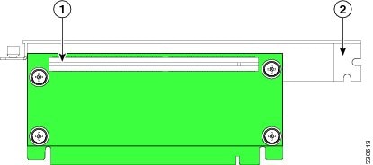
Figure 3-27 PCIe Riser Assembly Side View
|
|
|
Replacing a PCIe Card in a Motherboard Slot
Note![]() If you replace an LSI MegaRAID controller card, you must restore your RAID configuration to the new card. See Restoring RAID Configuration After Replacing a RAID Controller.
If you replace an LSI MegaRAID controller card, you must restore your RAID configuration to the new card. See Restoring RAID Configuration After Replacing a RAID Controller.
To install or replace a PCIe card in low-profile motherboard slots 2 through 6, follow these steps:
Step 1![]() Remove a PCIe card (or a blank filler panel):
Remove a PCIe card (or a blank filler panel):
a.![]() Shut down and power off the server as described in the “Shutting Down and Powering Off the Server” section.
Shut down and power off the server as described in the “Shutting Down and Powering Off the Server” section.
b.![]() Slide the server out the front of the rack far enough so that you can remove the top cover. You might have to detach cables from the rear panel to provide clearance.
Slide the server out the front of the rack far enough so that you can remove the top cover. You might have to detach cables from the rear panel to provide clearance.
c.![]() Remove the top cover as described in the “Removing and Replacing the Server Top Cover” section.
Remove the top cover as described in the “Removing and Replacing the Server Top Cover” section.
d.![]() Remove any cables from the rear ports of the PCIe card that you are replacing.
Remove any cables from the rear ports of the PCIe card that you are replacing.
Tip Label the cables when you disconnect them to aid correct connection to the new card.
e.![]() Open the hinged PCIe card retainer. Pinch the two release latches toward the center of the retainer while you lift up on the front edge of the retainer to open it. See Figure 3-24.
Open the hinged PCIe card retainer. Pinch the two release latches toward the center of the retainer while you lift up on the front edge of the retainer to open it. See Figure 3-24.
f.![]() Lift the card straight up from the motherboard connector.
Lift the card straight up from the motherboard connector.
Note![]() Lift up on both ends of the card evenly to avoid damaging its connector.
Lift up on both ends of the card evenly to avoid damaging its connector.
a.![]() Align the PCIe card with the empty PCIe connector on the motherboard.
Align the PCIe card with the empty PCIe connector on the motherboard.
b.![]() Push down evenly on both ends of the card until it is fully seated in the motherboard connector.
Push down evenly on both ends of the card until it is fully seated in the motherboard connector.
c.![]() Ensure that the card rear panel sits flat against the chassis rear panel opening.
Ensure that the card rear panel sits flat against the chassis rear panel opening.
d.![]() Close the hinged PCIe retainer and push down on it in the closed position until the latches lock in place.
Close the hinged PCIe retainer and push down on it in the closed position until the latches lock in place.
f.![]() Replace the server in the rack, replace cables, and then power on the server by pressing the Power button.
Replace the server in the rack, replace cables, and then power on the server by pressing the Power button.
Step 3![]() If the card that you replaced is a mass storage controller, restore the RAID configuration on your drives to the new mass storage controller.
If the card that you replaced is a mass storage controller, restore the RAID configuration on your drives to the new mass storage controller.
See Restoring RAID Configuration After Replacing a RAID Controller.
Special Considerations for Cisco UCS Virtual Interface Cards
Table 3-6 describes the requirements for the supported Cisco UCS virtual interface cards (VICs).
|
|
|
|
|
|
|
|
|---|---|---|---|---|---|---|
|
|
||||||
|
|
||||||
|
|
PCIE 77 |
|
6.See PCIe Slots. 7.The Cisco UCS VIC1225T is not supported for UCS integration at this time. |
Installing Multiple PCIe Cards and Resolving Limited Resources
When a large number of PCIe add-on cards are installed in the server, the system may run out of the following resources required for PCIe devices:
The topics in this section provide guidelines for resolving the issues related to these limited resources.
Resolving Insufficient Memory Space to Execute Option ROMs
The system has very limited memory to execute PCIe legacy option ROMs, so when a large number of PCIe add-on cards are installed in the server, the system BIOS might not able to execute all of the option ROMs. The system BIOS loads and executes the option ROMs in the order that the PCIe cards are enumerated (Slot 1, Slot 2, Slot 3, etc.).
If the system BIOS does not have sufficient memory space to load any PCIe option ROM, it skips loading that option ROM, reports a system event log (SEL) event to the CIMC controller and reports the following error in the Error Manager page of the BIOS Setup utility:
To resolve this issue, disable the Option ROMs that are not needed for system booting. The BIOS Setup Utility provides the setup options to enable or disable the Option ROMs at the PCIe slot level for the PCIe expansion slots and at the port level for the onboard NICs. These options can be found in the BIOS Setup Utility Advanced → PCI Configuration page (see Figure 3-28).
Figure 3-28 BIOS Setup Utility Advanced > PCI Configuration Page
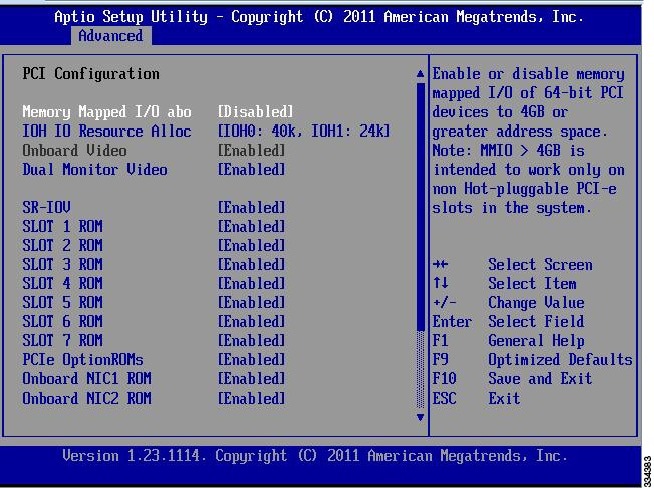
When this server is configured in the factory, the RAID controllers are installed in PCIe Slot 3 or Slot 5 for single RAID controller configuration, or in both Slot 3 and Slot 5 for dual RAID controller configuration.
If the server is configured to boot primarily from RAID storage, make sure that the option ROMs for Slot 3 and/or Slot 5 are enabled in the BIOS, depending your RAID controller configuration. If the RAID controller does not appear in the system boot order even with the option ROMs for Slot 3 and Slot 5 enabled, the RAID controller option ROM might not have sufficient memory space to execute. In that case, disable other option ROMs that are not needed for the system configuration to free up some memory space for the RAID controller option ROM.
If the system is configured to primarily perform PXE boot from onboard NICs, make sure that the option ROMs for the onboard NICs to be booted from are enabled in the BIOS Setup Utility. Disable other option ROMs that are not needed to create sufficient memory space for the onboard NICs.
Resolving Insufficient 16-Bit I/O Space
The system has only 64 KB of legacy 16-bit I/O resources available. This 64 KB of I/O space is divided between two I/O Hubs (IOH0 and IOH1) in the system.
The default BIOS setting is to allocate 40 KB to IOH0 and 24 KB to IOH1. Every PCIe device that is connected to IOH0 has to share the 40 KB of I/O. Every PCIe device connected to IOH1 must share that 24 KB of I/O.
When a large number of PCIe cards are installed in the system, the system BIOS might not have sufficient I/O space for some PCIe devices. If the system BIOS is not able to allocate the required I/O resources for any PCIe devices, the following symptoms have been observed:
- The BIOS might appear to hang while initializing PCIe devices.
- The PCIe option ROMs might take excessive time to complete, which appears to lock up the system.
- PCIe boot devices might not be accessible from the BIOS.
- PCIe option ROMs might report initialization errors. These errors are seen before the BIOS hands control to the operating system.
- The keyboard might not work.
To work around this problem, rebalance the load on each IOH using the following methods:
1.![]() Adjust the IOH IO Resource Allocation ratio. This option is included in the BIOS Setup Utility Advanced → PCI Configuration page (see Figure 3-28).
Adjust the IOH IO Resource Allocation ratio. This option is included in the BIOS Setup Utility Advanced → PCI Configuration page (see Figure 3-28).
2.![]() Physically remove any unused PCIe cards.
Physically remove any unused PCIe cards.
3.![]() Physically rearrange the PCIe cards to create a balance between IOH0 and IOH1.
Physically rearrange the PCIe cards to create a balance between IOH0 and IOH1.
In this server, the PCIe slots are connected to IOH0 and IOH1 as follows:
Replacing the RAID Controller Battery Backup Unit
This server supports installation of up to two LSI RAID controller battery backup units (BBUs).
Note![]() This optional LSI BBU is available only when using the optional LSI 9260-8i SAS MegaRAID controller card. This BBU provides approximately 72 hours of battery backup for the disk write-back cache DRAM in the case of sudden power loss.
This optional LSI BBU is available only when using the optional LSI 9260-8i SAS MegaRAID controller card. This BBU provides approximately 72 hours of battery backup for the disk write-back cache DRAM in the case of sudden power loss.
Note![]() LSI recommends that you replace the LSI BBU once per year or after 1,000 recharge cycles, whichever comes first. Verify whether BBU replacement is required by looking in the CIMC. Log in to CIMC for the server, then click Server—Inventory—Storage—Battery Backup Unit. If the Battery Replacement Required field says, “True,” then you must purchase a replacement BBU and replace it.
LSI recommends that you replace the LSI BBU once per year or after 1,000 recharge cycles, whichever comes first. Verify whether BBU replacement is required by looking in the CIMC. Log in to CIMC for the server, then click Server—Inventory—Storage—Battery Backup Unit. If the Battery Replacement Required field says, “True,” then you must purchase a replacement BBU and replace it.
Warning![]() There is danger of explosion if the battery is replaced incorrectly. Replace the battery only with the same or equivalent type recommended by the manufacturer. Dispose of used batteries according to the manufacturer’s instructions.
There is danger of explosion if the battery is replaced incorrectly. Replace the battery only with the same or equivalent type recommended by the manufacturer. Dispose of used batteries according to the manufacturer’s instructions.
Statement 1015
To replace the RAID controller BBU, follow these steps:
Step 1![]() Remove a BBU (see Figure 3-29).
Remove a BBU (see Figure 3-29).
a.![]() Power off the server as described in the “Shutting Down and Powering Off the Server” section.
Power off the server as described in the “Shutting Down and Powering Off the Server” section.
b.![]() Slide the server out the front of the rack far enough so that you can remove the top cover. You might have to detach cables from the rear panel to provide clearance.
Slide the server out the front of the rack far enough so that you can remove the top cover. You might have to detach cables from the rear panel to provide clearance.
c.![]() Remove the top cover as described in the “Removing and Replacing the Server Top Cover” section.
Remove the top cover as described in the “Removing and Replacing the Server Top Cover” section.
d.![]() Disconnect the cable that is attached to the BBU.
Disconnect the cable that is attached to the BBU.
e.![]() Grasp the plastic BBU holder and slide it upward to free its slotted holes from the two mounting pegs on the inner chassis wall.
Grasp the plastic BBU holder and slide it upward to free its slotted holes from the two mounting pegs on the inner chassis wall.
f.![]() Pull the retainer clip on the plastic BBU holder away from the BBU and then lift the BBU from the holder.
Pull the retainer clip on the plastic BBU holder away from the BBU and then lift the BBU from the holder.
a.![]() Set the new BBU into the plastic BBU holder and push it flat so that retaining clip closes over the BBU.
Set the new BBU into the plastic BBU holder and push it flat so that retaining clip closes over the BBU.
b.![]() Insert the plastic BBU holder against the inner chassis wall and align the two holes in the back of the holder with the two pegs on the chassis wall.
Insert the plastic BBU holder against the inner chassis wall and align the two holes in the back of the holder with the two pegs on the chassis wall.
c.![]() Push the plastic BBU holder downward on the two mounting pegs until it stops.
Push the plastic BBU holder downward on the two mounting pegs until it stops.
d.![]() Connect the cable from the RAID controller to the new BBU.
Connect the cable from the RAID controller to the new BBU.
f.![]() Replace the server in the rack, replace cables, and then power on the server by pressing the Power button.
Replace the server in the rack, replace cables, and then power on the server by pressing the Power button.
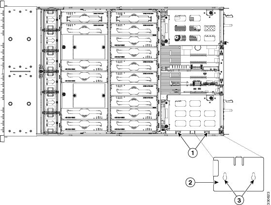
|
|
|
||
|
|
|
Installing a Trusted Platform Module
The trusted platform module (TPM) is a small circuit board that attaches to a motherboard socket. The socket location is on the motherboard, underneath the cage for power supply 1.
Note![]() For security purposes, the TPM is installed with a one-way screw. It cannot be removed with a standard screwdriver.
For security purposes, the TPM is installed with a one-way screw. It cannot be removed with a standard screwdriver.
To install a trusted platform module (TPM), follow these steps:
Step 1![]() Prepare the server for component installation.
Prepare the server for component installation.
a.![]() Power off the server as described in the “Shutting Down and Powering Off the Server” section.
Power off the server as described in the “Shutting Down and Powering Off the Server” section.
b.![]() Slide the server out the front of the rack far enough so that you can remove the top cover. You might have to detach cables from the rear panel to provide clearance.
Slide the server out the front of the rack far enough so that you can remove the top cover. You might have to detach cables from the rear panel to provide clearance.
c.![]() Remove the top cover as described in the “Removing and Replacing the Server Top Cover” section.
Remove the top cover as described in the “Removing and Replacing the Server Top Cover” section.
d.![]() Remove the PCIe riser assembly that is in PCIe slot 1 (see Figure 3-26). See Replacing a PCIe Riser Assembly for details.
Remove the PCIe riser assembly that is in PCIe slot 1 (see Figure 3-26). See Replacing a PCIe Riser Assembly for details.
e.![]() Remove power supply 1 from its cage. See Replacing Power Supplies for details.
Remove power supply 1 from its cage. See Replacing Power Supplies for details.
Step 2![]() Install a TPM (see Figure 3-30):
Install a TPM (see Figure 3-30):
a.![]() Locate the TPM socket on the motherboard, as shown in Figure 3-30.
Locate the TPM socket on the motherboard, as shown in Figure 3-30.
b.![]() Align the connector that is on the bottom of the TPM circuit board with the motherboard TPM socket. Align the screw hole and standoff on the TPM board with the screw hole adjacent to the TPM socket.
Align the connector that is on the bottom of the TPM circuit board with the motherboard TPM socket. Align the screw hole and standoff on the TPM board with the screw hole adjacent to the TPM socket.
c.![]() Push down evenly on the TPM to seat it in the motherboard socket.
Push down evenly on the TPM to seat it in the motherboard socket.
d.![]() Install the single one-way screw that secures the TPM to the motherboard.
Install the single one-way screw that secures the TPM to the motherboard.
e.![]() Replace power supply 1 to the empty bay.
Replace power supply 1 to the empty bay.
f.![]() Replace the PCIe riser assembly to PCIe slot 1.
Replace the PCIe riser assembly to PCIe slot 1.
h.![]() Replace the server in the rack, replace cables, and then power on the server by pressing the Power button.
Replace the server in the rack, replace cables, and then power on the server by pressing the Power button.
a.![]() Watch during bootup for the F2 prompt, and then press F2 to enter BIOS setup.
Watch during bootup for the F2 prompt, and then press F2 to enter BIOS setup.
b.![]() Log into the BIOS Setup utility with your BIOS Administrator password.
Log into the BIOS Setup utility with your BIOS Administrator password.
c.![]() On the BIOS Setup utility screen, select the Advanced tab.
On the BIOS Setup utility screen, select the Advanced tab.
d.![]() Select Trusted Computing to open the TPM Security Device Configuration screen.
Select Trusted Computing to open the TPM Security Device Configuration screen.
e.![]() Change TPM SUPPORT to Enabled.
Change TPM SUPPORT to Enabled.
f.![]() Press F10 to save your settings and reboot the server.
Press F10 to save your settings and reboot the server.
Step 4![]() Verify that the TPM is now enabled.
Verify that the TPM is now enabled.
a.![]() Watch during bootup for the F2 prompt, and then press F2 to enter BIOS setup.
Watch during bootup for the F2 prompt, and then press F2 to enter BIOS setup.
b.![]() Log into the BIOS Setup utility with your BIOS Administrator password.
Log into the BIOS Setup utility with your BIOS Administrator password.
d.![]() Select Trusted Computing to open the TPM Security Device Configuration screen.
Select Trusted Computing to open the TPM Security Device Configuration screen.
e.![]() Verify that TPM SUPPORT is Enabled.
Verify that TPM SUPPORT is Enabled.
Note![]() If you want to use the Intel Trusted Execution Technology (TXT) feature, it must be enabled in the server BIOS as described in Enabling the Intel Trusted Execution Technology (TXT) Feature For the TPM.
If you want to use the Intel Trusted Execution Technology (TXT) feature, it must be enabled in the server BIOS as described in Enabling the Intel Trusted Execution Technology (TXT) Feature For the TPM.
Figure 3-30 TPM Socket Location on Motherboard
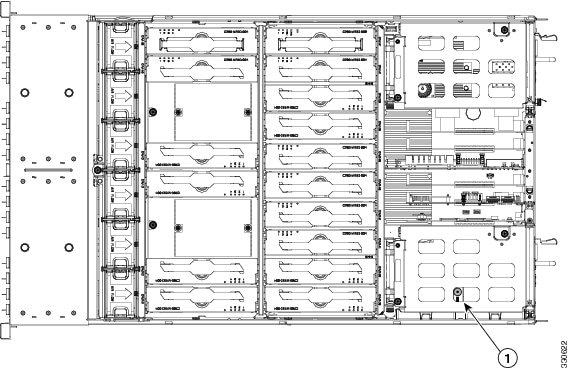
|
|
TPM socket and screw hole on motherboard (visible through power supply cage with PCIe riser and power supply removed) |
|
Enabling the Intel Trusted Execution Technology (TXT) Feature For the TPM
Intel TXT provides greater protection for information that is used and stored on the business server. A key aspect of that protection is the provision of an isolated execution environment and associated sections of memory where operations can be conducted on sensitive data, invisibly to the rest of the system. Likewise, Intel TXT provides for a sealed portion of storage where sensitive data such as encryption keys can be kept, helping to shield them from being compromised during an attack by malicious code.
To enable the TXT feature, follow these steps:
Step 1![]() Verify that a TPM is now installed and enabled in the server:
Verify that a TPM is now installed and enabled in the server:
a.![]() Either attach a VGA monitor and USB keyboard to the server, or log in remotely to the CIMC interface of the server and open a virtual KVM console window.
Either attach a VGA monitor and USB keyboard to the server, or log in remotely to the CIMC interface of the server and open a virtual KVM console window.
c.![]() Watch during bootup for the F2 prompt, and then press F2 to enter BIOS setup.
Watch during bootup for the F2 prompt, and then press F2 to enter BIOS setup.
d.![]() Log in to the BIOS Setup utility with your BIOS Administrator password.
Log in to the BIOS Setup utility with your BIOS Administrator password.
Note![]() You must be logged in as the BIOS administrator to perform this procedure. If you have not done so already, set a BIOS administrator password on the Security tab of the BIOS Setup utility.
You must be logged in as the BIOS administrator to perform this procedure. If you have not done so already, set a BIOS administrator password on the Security tab of the BIOS Setup utility.
f.![]() On the Advanced tab, select Trusted Computing to open the TPM Security Device Configuration screen.
On the Advanced tab, select Trusted Computing to open the TPM Security Device Configuration screen.
g.![]() Verify that TPM SUPPORT is Enabled. If it is not, set TPM SUPPORT to Enabled.
Verify that TPM SUPPORT is Enabled. If it is not, set TPM SUPPORT to Enabled.
h.![]() Press Escape to return to the BIOS Setup utility Advanced tab.
Press Escape to return to the BIOS Setup utility Advanced tab.
Step 2![]() Enable the Intel Trusted Execution Technology (TXT) feature:
Enable the Intel Trusted Execution Technology (TXT) feature:
a.![]() On the Advanced tab, select Intel TXT(LT-SX) Configuration to open the Intel TXT(LT-SX) Hardware Support screen.
On the Advanced tab, select Intel TXT(LT-SX) Configuration to open the Intel TXT(LT-SX) Hardware Support screen.
Note![]() The Intel Trusted Execution Technology feature can be enabled only when the server has a TPM installed on the TPM header.
The Intel Trusted Execution Technology feature can be enabled only when the server has a TPM installed on the TPM header.
b.![]() Set TXT Support to Enabled.
Set TXT Support to Enabled.
Step 3![]() On the same screen, verify that the Intel Virtualization Technology (VT) and the Intel VT for Directed I/O (VT-d) features are enabled (the factory default).
On the same screen, verify that the Intel Virtualization Technology (VT) and the Intel VT for Directed I/O (VT-d) features are enabled (the factory default).
a.![]() On the Intel TXT(LT-SX) Hardware Support screen, verify that VT-d Support and VT Support are both listed as Enabled.
On the Intel TXT(LT-SX) Hardware Support screen, verify that VT-d Support and VT Support are both listed as Enabled.
–![]() If they are already enabled, skip to Step 4.
If they are already enabled, skip to Step 4.
–![]() If VT-d Support and VT Support are not enabled, continue with the next steps to enable them.
If VT-d Support and VT Support are not enabled, continue with the next steps to enable them.
b.![]() Press Escape to return to the BIOS Setup utility Advanced tab.
Press Escape to return to the BIOS Setup utility Advanced tab.
c.![]() On the Advanced tab, select Processor Configuration to open the Processor Configuration screen.
On the Advanced tab, select Processor Configuration to open the Processor Configuration screen.
d.![]() Set Intel (R) VT and Intel (R) VT-d to Enabled.
Set Intel (R) VT and Intel (R) VT-d to Enabled.
Step 4![]() Press F10 to save your changes and exit the BIOS Setup utility.
Press F10 to save your changes and exit the BIOS Setup utility.
Step 5![]() Verify that the Intel TXT, VT, and VT-d features are enabled:
Verify that the Intel TXT, VT, and VT-d features are enabled:
b.![]() Watch during bootup for the F2 prompt, and then press F2 to enter BIOS setup.
Watch during bootup for the F2 prompt, and then press F2 to enter BIOS setup.
d.![]() Select Intel TXT(LT-SX) Configuration and verify that TXT Support, VT-d Support, and VT Support are Enabled.
Select Intel TXT(LT-SX) Configuration and verify that TXT Support, VT-d Support, and VT Support are Enabled.
Replacing Power Supplies
The server can have one or two power supplies. When two power supplies are installed they are redundant as 1+1.
To replace or install a power supply, follow these steps:
Note![]() If you have ordered a server with power supply redundancy (two power supplies), you do not have to power off the server to replace power supplies because they are redundant as 1+1.
If you have ordered a server with power supply redundancy (two power supplies), you do not have to power off the server to replace power supplies because they are redundant as 1+1.
Step 1![]() Remove the power supply that you are replacing or a blank panel from an empty bay (see Figure 3-31):
Remove the power supply that you are replacing or a blank panel from an empty bay (see Figure 3-31):
a.![]() Perform one of the following actions:
Perform one of the following actions:
–![]() If your server has only one power supply, shut down and power off the server as described in the “Shutting Down and Powering Off the Server” section.
If your server has only one power supply, shut down and power off the server as described in the “Shutting Down and Powering Off the Server” section.
–![]() If your server has two power supplies, you do not have to shut down the server.
If your server has two power supplies, you do not have to shut down the server.
b.![]() Remove the power cord from the power supply that you are replacing.
Remove the power cord from the power supply that you are replacing.
c.![]() Grasp the power supply handle while pinching the release lever towards the handle.
Grasp the power supply handle while pinching the release lever towards the handle.
d.![]() Pull the power supply out of the bay.
Pull the power supply out of the bay.
Step 2![]() Install a new power supply:
Install a new power supply:
a.![]() Grasp the power supply handle and insert the new power supply into the empty bay.
Grasp the power supply handle and insert the new power supply into the empty bay.
b.![]() Push the power supply into the bay until the release lever locks.
Push the power supply into the bay until the release lever locks.
c.![]() Connect the power cord to the new power supply.
Connect the power cord to the new power supply.
d.![]() If you shut down the server, press the Power button to return the server to main power mode.
If you shut down the server, press the Power button to return the server to main power mode.
Figure 3-31 Removing and Replacing Power Supplies
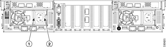
|
|
|
Enabling or Disabling the Internal USB Port
The factory default is for all USB ports on the server to be enabled. However, the internal USB port can be enabled or disabled in the server BIOS. To enable or disable the internal USB port, follow these steps:
Step 1![]() Enter the BIOS Setup utility by pressing the F2 key when prompted during bootup.
Enter the BIOS Setup utility by pressing the F2 key when prompted during bootup.
Step 2![]() Navigate to the Advanced tab.
Navigate to the Advanced tab.
Step 3![]() On the Advanced tab, select USB Configuration.
On the Advanced tab, select USB Configuration.
Step 4![]() On the USB Configuration page, select USB Ports Configuration.
On the USB Configuration page, select USB Ports Configuration.
Step 5![]() Scroll to USB Port: Internal, press Enter, and then select either Enabled or Disabled from the pop-up menu.
Scroll to USB Port: Internal, press Enter, and then select either Enabled or Disabled from the pop-up menu.
Step 6![]() Press F10 to save and exit the utility.
Press F10 to save and exit the utility.
 Feedback