Power Supply and Fan Module Installation
• Installing an AC-Power Supply Module
•Installing an DC-Power Supply Module
For module descriptions, see the "Fan Modules" section and the "Power Supply Modules" section.
Installation Guidelines
Observe these guidelines when removing or installing a power supply module or fan module:
 |
Caution Do not force the power supply module or fan module into the slot. This can damage the pins on the XPS if they are not aligned with the module.
|
•A power supply or fan module that is only partially connected to the XPS can disrupt the system operation.
•Remove power from the power supply module before removing or installing it.
•In redundant mode: You can hot swap a power supply module when a device is connected to it or when the XPS is not backing up a device.
 |
Warning Do not reach into a vacant slot or chassis while you install or remove a module or a fan. Exposed circuitry could constitute an energy hazard. Statement 206
|
|
Warning Only trained and qualified personnel should be allowed to install, replace, or service this equipment. Statement 1030
|
Installing an AC-Power Supply Module
|
Warning The plug-socket combination must be accessible at all times, because it serves as the main disconnecting device. Statement 1019
|
To remove and install an AC-power supply module, follow these steps:
Step 1 Turn off the power at its source.
Step 2 Remove the power cord from the power cord retainer.
Step 3 Remove the power cord from the power connector.
Step 4 Press the release latch at the right side of the power supply module inward, and slide the power supply out.
|
Caution Do not leave the power supply slot open for more than 90 seconds while the switch is operating.
|
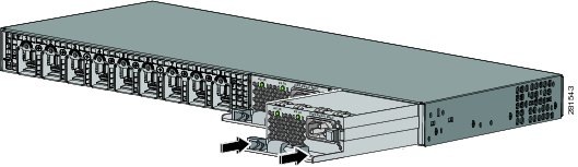
Step 5 Install the power supply into the power supply slot, and gently push it into the slot. When correctly inserted, the 350-W and 715-W power supply modules (excluding the power cord retainer) are flush with the rear panel. The 1100-W power supply module extends 1.5 inches from the rear panel (see Figure 3-1).
When inserting a power supply module into the XPS, do not use unnecessary force. Doing so can damage the connectors on the rear of the supply and on the midplane.
Figure 3-1 Inserting the AC-Power Supply Module
Step 6 (Optional) Make a loop in the power cord, and thread it through the power cord retainer (see Figure 3-2).
Figure 3-2 AC- Power Supply Module with Power Cord Retainer

|
Warning Take care when connecting units to the supply circuit so that wiring is not overloaded. Statement 1018
|
Step 7 Connect the power cord to the power supply and to an AC power outlet.
Step 8 Confirm that the power supply AC OK and PS OK LEDs are green. See Table 1-5 for a description of the module LEDs.
Installing an DC-Power Supply Module
•Installing the DC Power Supply in the XPS
•Wiring the DC Input Power Source
|
Warning This product relies on the building's installation for short-circuit (overcurrent) protection. Ensure that the protective device is rated not greater than: 20 A. Statement 1005
|
|
Warning A readily accessible two-poled disconnect device must be incorporated in the fixed wiring. Statement 1022
|
 |
Note The grounding architecture of this product is DC-isolated (DC-I)
|
Tools That You Need
•Number-2 Phillips head ratcheting screwdriver that exerts up to 15 pound-force inches (lbf-in.) of pressure.
•Panduit crimping tool with optional controlled-cycle mechanism (model CT-720, CT-920, CT-920CH, CT-930, or CT-940CH).
•Wire-stripping tools.
•Four leads of 14-gauge copper wire.
Installing the DC Power Supply in the XPS
Step 1 Turn off DC power. To ensure that power is off, change the circuit breakers to the OFF position, and tape the circuit-breaker switches in the OFF position.
Step 2 Remove the plastic safety cover from the power supply terminal block (Figure 1-9).
Step 3 Insert the power supply in the power-supply slot, and gently push it into the slot (Figure 3-3). When correctly installed, the DC power supply (excluding the extraction handle) is flush with the rear panel.
Figure 3-3 Inserting the DC Power Supply in the Switch

Step 4 Connect the input power as described in the "Wiring the DC Input Power Source" section.
Wiring the DC Input Power Source
Step 1 Using a wire-stripping tool, strip each of the four wires from the DC-input power source to the appropriate length for the terminals.
|
Warning Use copper conductors only. Statement 1025
|
Step 2 Using a Panduit crimping tool, crimp the fork-type terminals to the copper conductor, 90C, 14-AWG DC power input wires.
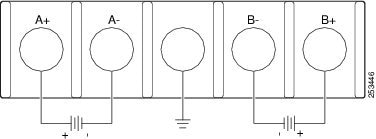
Step 3 Connect the DC-input power terminals to the terminal blocks. See Figure 3-4 or Figure 3-5. Make sure to match the polarity (negative to negative, positive to positive) when connecting the wires to the terminal blocks. Connect the ground wire to a grounded metal rack or to earth ground if the XPS 2200 is not in a grounded rack.
Figure 3-4 DC Source A Isolated From Source B with No Common Ground
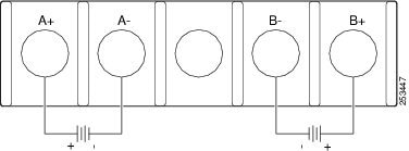
Figure 3-5 DC Source A and Source B Connections with Common Ground
Step 4 Torque all terminal block screws to 11 lbf-in.
Step 5 Replace the terminal block safety cover.
Step 6 Move the DC power source circuit-breakers to the ON position.
Step 7 Confirm that the power-supply DC OK and PS OK LEDs are green. See Table 1-5 for a description of the module LEDs.
Installing a Fan Module
Step 1 Pinch the fan module release handle, and slide the module out.
|
Caution You should replace the fan module within 5 minutes to avoid overheating the XPS.
|
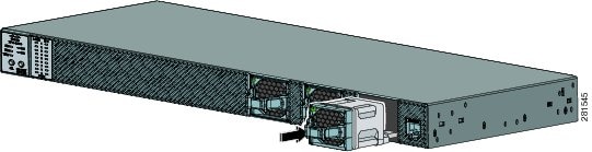
Step 2 Install the fan module in the fan slot, and firmly push it into the slot, applying pressure to the end of the module, not the extraction handles. (See Figure 3-6.) When correctly inserted, the fan module is flush with the front panel. When the fan is operating, a green LED is on in the top left corner of the fan module.
|
Warning Do not reach into a vacant slot or chassis while you install or remove a module or a fan. Exposed circuitry could constitute an energy hazard. Statement 206
|
Figure 3-6 Inserting the Fan Module
 Feedback