Cisco ME 3400E Ethernet Access Switch Power-Supply Module Quick Start Guide
Available Languages
Table Of Contents
Cisco ME 3400E Ethernet Access Switch Power-Supply Modules
Quick Start Guide
Cisco ME 3400E Ethernet Access Switch Power-Supply Modules
This document provides the high-level steps for installing the AC and the DC power-supply modules for the Cisco ME 3400E-24TS-M and the Cisco ME 3400EG-12CS-M switches. For the complete installation instructions, see the Cisco ME 3400E Ethernet Access Switch Hardware Installation Guide at this URL:
http://www.cisco.com/en/US/docs/switches/metro/me3400e/hardware/installation/guide/me3400e_hig.html
For a complete list of the safety warnings in the required languages, see the Regulatory Compliance and Safety Information for the Cisco ME 3400E Switch on the Documentation CD.
Observe these warnings when you install and power-on the power-supply module:

Warning
Do not reach into a vacant slot or chassis while you install or remove a module or a fan. Exposed circuitry could constitute an energy hazard. Statement 206
Warning
Warning
For DC power-supply modules, observe these warnings:
Warning
Warning
Warning
Warning
For all power-supply modules, review these caution statements:

Caution

Note
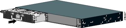
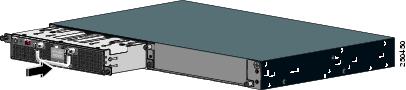
The power-supply module slots are on the switch rear panel, and the power connectors are on the front panel.
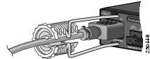
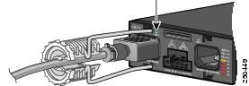
Install the AC Power-Supply Module
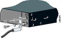
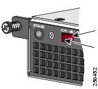
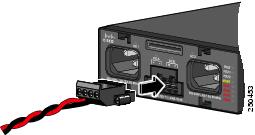
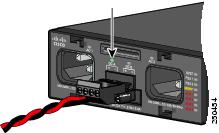
Install the DC Power-Supply Module
CCDE, CCENT, Cisco Eos, Cisco Lumin, Cisco Nexus, Cisco StadiumVision, Cisco TelePresence, Cisco WebEx, the Cisco logo, DCE, and Welcome to the Human Network are trademarks; Changing the Way We Work, Live, Play, and Learn and Cisco Store are service marks; and Access Registrar, Aironet, AsyncOS, Bringing the Meeting To You, Catalyst, CCDA, CCDP, CCIE, CCIP, CCNA, CCNP, CCSP, CCVP, Cisco, the Cisco Certified Internetwork Expert logo, Cisco IOS, Cisco Press, Cisco Systems, Cisco Systems Capital, the Cisco Systems logo, Cisco Unity, Collaboration Without Limitation, EtherFast, EtherSwitch, Event Center, Fast Step, Follow Me Browsing, FormShare, GigaDrive, HomeLink, Internet Quotient, IOS, iPhone, iQuick Study, IronPort, the IronPort logo, LightStream, Linksys, MediaTone, MeetingPlace, MeetingPlace Chime Sound, MGX, Networkers, Networking Academy, Network Registrar, PCNow, PIX, PowerPanels, ProConnect, ScriptShare, SenderBase, SMARTnet, Spectrum Expert, StackWise, The Fastest Way to Increase Your Internet Quotient, TransPath, WebEx, and the WebEx logo are registered trademarks of Cisco Systems, Inc. and/or its affiliates in the United States and certain other countries.
All other trademarks mentioned in this document or website are the property of their respective owners. The use of the word partner does not imply a partnership relationship between Cisco and any other company. (0809R)
 Feedback
Contact Cisco
- Open a Support Case

- (Requires a Cisco Service Contract)