Cisco Center Rack-Mount Kits Installation Note
Available Languages
Table Of Contents
Cisco Center Rack-Mount Kits Installation Note
Statement 1071—Warning Definition
Center Rack-Mounting a Catalyst 6506 and Catalyst 6506-E Switch Chassis
Center Rack-Mounting a Catalyst 6509 and Catalyst 6509-E Switch Chassis
Center Rack-Mounting a Catalyst 6513 Switch Chassis
Obtaining Documentation and Submitting a Service Request
Cisco Center Rack-Mount Kits Installation Note
Product Numbers: WS-C6597= and WS-6513-RACK-MNT=
This installation note contains instructions on how to install the Catalyst 6500 series switches in a telco-style rack using the two center rack-mount kits.

Note
Use these kits in place of the rack-mount brackets shipped installed on the chassis, and only when you are center rack-mounting a Catalyst switch in a telco-style rack.
Contents
This installation note contains the following sections:
•
•
•
•
Overview
The two center rack-mount kits and the Catalyst switch chassis they support are listed in Table 1.
Note
The center rack-mount kits are installed differently depending on the chassis. Table 2 lists the switch chassis and summarizes how the center rack-mount kits are installed.
Safety
Safety warnings appear throughout this publication in procedures that may harm you if performed incorrectly. A warning symbol precedes each warning statement.
Statement 1071—Warning Definition
7

Warning
Tools Required
You will need the following tools to install the center rack-mount kits on your 6-, 9-, or 13-slot chassis. If you need additional parts or assistance, contact your technical support representative.
•
•
•
•
9
Center Rack-Mounting a Catalyst 6506 and Catalyst 6506-E Switch Chassis
This section describes how to install the Catalyst 6506 and Catalyst 6506-E switch chassis in a telco-style rack using the center rack-mount kit (WS-C6597=). For the Catalyst 6506 and Catalyst 6506-E switch chassis, you need to install the two center rack-mount kit brackets to the bottom sides of the chassis.
Note
Note
To install the Catalyst 6506 or Catalyst 6506-E switch chassis in a telco-style rack using the WS-C6597 center rack-mount kit, perform these steps:
Step 1
Step 2
Figure 1 Attaching the Center Rack-Mount Kit Brackets to the Catalyst 6506 and Catalyst 6506-E Switch Chassis
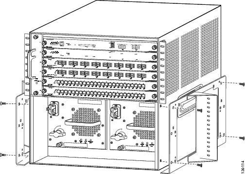
Step 3
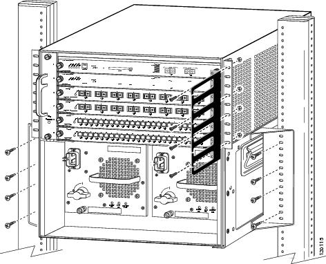
Figure 2 Installing the Catalyst 6506 and Catalyst 6506-E Switch Chassis in a Telco-Style Rack
Center Rack-Mounting a Catalyst 6509 and Catalyst 6509-E Switch Chassis
This section describes how to rack-mount a Catalyst 6509 and Catalyst 6509-E switch chassis in a telco-style rack using the WS-C6597 center rack-mount kit. For the Catalyst 6509 and Catalyst 6509-E switch chassis, you need to install the two center rack-mount kit brackets to the bottom sides of the chassis.
Note
Note
To install the Catalyst 6509 and Catalyst 6509-E switch chassis in a telco-style rack using the WS-C6597 center rack-mount kit, perform these steps:
Step 1
Step 2
Figure 3 Attaching the Center Rack-Mount Kit Brackets to the Catalyst 6509 and Catalyst 6509-E Switch Chassis
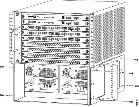
Step 3
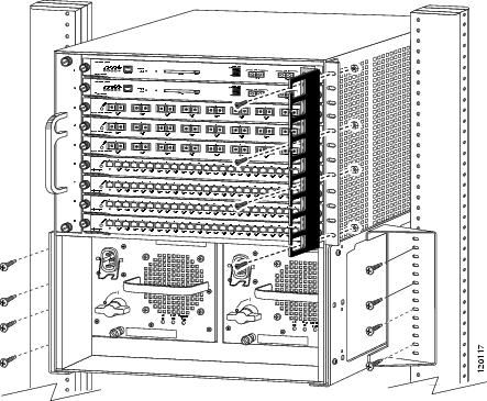
Figure 4 Installing the Catalyst 6509 and Catalyst 6509-E Switch Chassis in a Telco-Style Rack
Center Rack-Mounting a Catalyst 6513 Switch Chassis
This section describes how to install the Catalyst 6513 chassis in a telco-style rack using the WS-6513-RACK-MNT center rack-mount kit. In this procedure, the two lower brackets are used as a shelf and are not attached to the chassis. The two upper brackets are attached to the chassis and are secured to the telco-style rack.
Note
To install the Catalyst 6513 chassis in a telco-style rack using the WS-6513-RACK-MNT center rack-mount kit, perform these steps:
Step 1
Step 2
Figure 5 Attaching the Center Rack-Mount Kit Brackets to the Telco-Style Rack
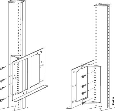
Step 3
Figure 6 Attaching the Upper Brackets to the Catalyst 6513 Switch Chassis

Step 4
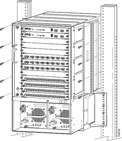
Step 5
Figure 7 Securing the Catalyst 6513 Switch Chassis in the Telco-Style Rack
Obtaining Documentation and Submitting a Service Request
For information on obtaining documentation, submitting a service request, and gathering additional information, see the monthly What's New in Cisco Product Documentation, which also lists all new and revised Cisco technical documentation, at:
http://www.cisco.com/en/US/docs/general/whatsnew/whatsnew.html
Subscribe to the What's New in Cisco Product Documentation as a Really Simple Syndication (RSS) feed and set content to be delivered directly to your desktop using a reader application. The RSS feeds are a free service and Cisco currently supports RSS Version 2.0.
This document is to be used in conjunction with the installation documentation that accompanied your product.
CCSP, the Cisco Square Bridge logo, Follow Me Browsing, and StackWise are trademarks of Cisco Systems, Inc.; Changing the Way We Work, Live, Play, and Learn, and iQuick Study are service marks of Cisco Systems, Inc.; and Access Registrar, Aironet, ASIST, BPX, Catalyst, CCDA, CCDP, CCIE, CCIP, CCNA, CCNP, Cisco, the Cisco Certified Internetwork Expert logo, Cisco IOS, Cisco Press, Cisco Systems, Cisco Systems Capital, the Cisco Systems logo, Cisco Unity, Empowering the Internet Generation, Enterprise/Solver, EtherChannel, EtherFast, EtherSwitch, Fast Step, FormShare, GigaDrive, GigaStack, HomeLink, Internet Quotient, IOS, IP/TV, iQ Expertise, the iQ logo, iQ Net Readiness Scorecard, LightStream, Linksys, MeetingPlace, MGX, the Networkers logo, Networking Academy, Network Registrar, Packet, PIX, Post-Routing, Pre-Routing, ProConnect, RateMUX, ScriptShare, SlideCast, SMARTnet, StrataView Plus, SwitchProbe, TeleRouter, The Fastest Way to Increase Your Internet Quotient, TransPath, and VCO are registered trademarks of Cisco Systems, Inc. and/or its affiliates in the United States and certain other countries.
All other trademarks mentioned in this document or Website are the property of their respective owners. The use of the word partner does not imply a partnership relationship between Cisco and any other company. (0411R)
Copyright © 2004 Cisco Systems, Inc. All rights reserved.


 Feedback
Contact Cisco
- Open a Support Case

- (Requires a Cisco Service Contract)