Catalyst 6500 Series PFC3B and PFC3BXL Installation Note
Available Languages
Table Of Contents
Catalyst 6500 Series PFC3B, PFC3BXL, PFC3C, and PFC3CXL Installation Note
Preparing the Supervisor Engine 720
Removing the PFC3A from the Supervisor Engine 720
Applying the Label to the Supervisor Engine
Obtaining Documentation and Submitting a Service Request
Catalyst 6500 Series PFC3B, PFC3BXL, PFC3C, and PFC3CXL Installation Note
Product number: WS-F6K-PFC3B=, WS-F6K-PFC3BXL=, WS-F6K-PFC3C=, WS-F6K-PFC3CXL=
This publication describes how to install the Catalyst 6500 Series Policy Feature Card 3B (PFC3B) or PFC3BXL, and Catalyst 6500 Series Policy Feature Card 3C (PFC3C) or PFC3CXL on a Supervisor Engine 720.

Note
To use the PFC3BXL or PFC3CXL, you must also upgrade the switch processor (SP) and route processor (RP) memory on the Supervisor Engine 720 to 1 GB each using the included DRAM DIMMs. For information on upgrading the memory on the Supervisor Engine 720, refer to the Supervisor Engine 720 Switch Processor and Route Processor Memory Installation Note at this URL:
http://www.cisco.com/en/US/docs/switches/lan/catalyst6500/hardware/Config_Notes/OL_20611.html
The Supervisor Engine 720 memory upgrade (MEM-MSFC2-1GB=) is an option when using the PFC3B or PFC3C.
Contents
This publication contains these sections:
•
•
•
•
•
Safety Overview
Safety warnings appear throughout this publication in procedures that, if performed incorrectly, may harm you. A warning symbol precedes each warning statement.
Warning
Warning
Warning
WarningParts List
These parts are in the WS-F6K-PFC3B=, WS-F6K-PFC3BXL=, WS-F6K-PFC3C=, or WS-F6K-PFC3CXL=kit:
•
•
•
•
•
Required Tools
Note
These tools are required to perform the installation of the PFC3B or PFC3C:
•
•
•
•
Installation Guidelines
Follow these guidelines when installing a PFC3B, PFC3BXL, PFC3C, PFC3CXL on a Supervisor Engine 720:
•
•
•

Caution
Caution
Caution
Caution
Caution
Preparing the Supervisor Engine 720
Note
To install the PFC3B or PFC3C on a Supervisor Engine 720, you must shut down the switch, remove the Supervisor Engine 720 from the chassis, and remove the PFC3A from the Supervisor Engine 720.
Caution
Before you remove a supervisor engine, you should first upload the current configuration to a server. This saves time when bringing the module back online. You can recover the configuration by downloading it from the server to the nonvolatile memory of the supervisor engine. For more information, refer to Chapter 26, "Working with Configuration Files," in the Catalyst 6500 Series Software Configuration Guide.
To prepare the Supervisor Engine 720 for the PFC3B or PFC3C, follow these steps:
Step 1
Step 2
Step 3
Step 4
Removing the PFC3A from the Supervisor Engine 720
To remove the PFC3A from the Supervisor Engine 720, follow these steps:
Step 1
Note
Figure 1 Removing Securing Screws and Cap Nuts
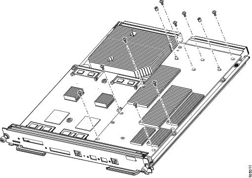
Caution
Step 2
Figure 2 Removing the PFC3A
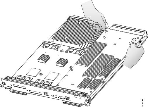
Step 3
Installing the PFC3B or PFC3C
Note
To install the PFC3B or PFC3C on the Supervisor Engine 720, follow these steps:
Step 1
Step 2
Figure 3 Inserting the PFC3B or PFC3C Under the EMI Gasket
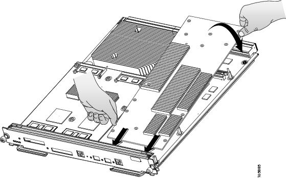
Caution
Step 3
Figure 4 Male Standoff Location on the Supervisor Engine 720
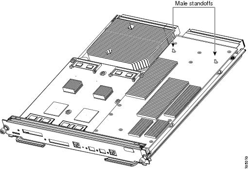
Caution
Caution
Step 4
Figure 5 Seating the PFC3B or PFC3C on the Supervisor Engine
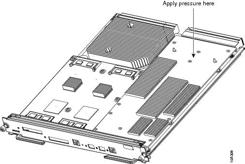
Caution
Note
Step 5
Figure 6 Installing the Supplied Screws
Note
http://www.cisco.com/en/US/docs/switches/lan/catalyst6500/hardware/Config_Notes/OL_20611.html
The Supervisor Engine 720 memory upgrade (MEM-MSFC2-1GB=) is an option when using the PFC3B or PFC3C.
Step 6
Step 7
Caution
Step 8
Step 9
Step 10
•
Verify that the switch is online. This indicates that the system acknowledges the new module and has brought it online.
•
Enter the show module command to verify that the system acknowledges the new module and has brought it online.
This example shows the output of the show module command:
Console> show moduleMod Slot Ports Module-Type Model Sub Status--- ---- ----- ------------------------- ------------------- --- --------1 1 48 10/100BaseTX Ethernet WS-X6248-RJ-45 no ok5 5 2 1000BaseX Supervisor WS-SUP720-BASE yes ok15 5 1 Multilayer Switch Feature WS-SUP720 no ok...Mod Sub-Type Sub-Model Sub-Serial Sub-Hw Sub-Sw--- ----------------------- ------------------- ----------- ------ ------5 L3 Switching Engine III WS-F6K-PFC3BXL SAD073702HH 0.250Console>If the installation is not successful, see the "Troubleshooting" section for troubleshooting information.
Applying the Label to the Supervisor Engine
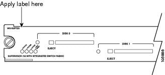
The WS-F6K-PFC3B=, WS-F6K-PFC3BXL=, WS-F6K-PFC3C=, or WS-F6K-PFC3CXL= kits include a packet of labels. Apply the "PFC3B", "PFC3BXL", "PFC3C" or "PFC3CXL"label to the upper-left corner of the Supervisor Engine 720 front panel. (See Figure 7.)
Figure 7 Applying the Label
Troubleshooting
Table 1 describes the basic troubleshooting information.
Table 1 Troubleshooting
The supervisor engine fails online diagnostics.
Remove the supervisor engine from the chassis and make sure that all securing screws and cap nuts are tight. See Figure 6 for screw locations.
The supervisor engine experiences a software-forced reset or boots to ROMMON.
The supervisor engine does not boot up (no power to supervisor engine, no console prompt, no STATUS LED).
Remove the supervisor engine from the chassis and reseat the SP and RP memory modules.
If these solutions do not resolve the issue, see the "Obtaining Documentation and Submitting a Service Request" section for information on obtaining technical assistance.
Related Documentation
For additional information on Catalyst 6500 series switches and command-line interface (CLI) commands, refer to the following publications:
•
•
•
•
•
•
•
•
Obtaining Documentation and Submitting a Service Request
For information on obtaining documentation, submitting a service request, and gathering additional information, see the monthly What's New in Cisco Product Documentation, which also lists all new and revised Cisco technical documentation, at:
http://www.cisco.com/en/US/docs/general/whatsnew/whatsnew.html
Subscribe to the What's New in Cisco Product Documentation as a Really Simple Syndication (RSS) feed and set content to be delivered directly to your desktop using a reader application. The RSS feeds are a free service and Cisco currently supports RSS Version 2.0.
This document is to be used in conjunction with the documents listed in the "Related Documentation" section.
Cisco and the Cisco logo are trademarks or registered trademarks of Cisco and/or its affiliates in the U.S. and other countries. To view a list of Cisco trademarks, go to this URL: www.cisco.com/go/trademarks. Third-party trademarks mentioned are the property of their respective owners. The use of the word partner does not imply a partnership relationship between Cisco and any other company. (1110R)
Copyright © 2004-2013 Cisco Systems, Inc. All rights reserved.

 Feedback
Contact Cisco
- Open a Support Case

- (Requires a Cisco Service Contract)