Catalyst 6500 Series Distributed Forwarding Card 3 for WS-X67xx Modules Installation Note
Available Languages
Table of Contents
Catalyst 6500 Series Distributed Forwarding Card3 for WS-X67xx Modules Installation Note
Statement 1071—Warning Definition
Removing a CFC or DFC Daughter Card
Removing the CFC Daughter Card
Removing the DFC3 Daughter Card
Removing the DFC3 Daughter Card from Modules without Stiffener Brackets
Removing the DFC3 Daughter Card from WS-X6748-GE-TX Modules Equipped with a Stiffener Bracket
Upgrading the Ethernet Module Memory
Installing the 1-GB Memory Module Upgrade
Installing the DFC3B and DFC3C Daughter Cards
Removing and Installing Ethernet Modules in the Chassis
Removing an Ethernet Module from the Chassis
Installing an Ethernet Module in the Chassis
Attaching Your ESD Grounding Strap
Obtaining Documentation and Submitting a Service Request
Catalyst 6500 Series Distributed Forwarding Card 3 for WS-X67xx Modules Installation Note
This publication describes the procedures for installing and removing the Distributed Forwarding Card 3 (DFC3) daughter card on the WS-X67xx Ethernet modules. The publication covers the following products:

Note![]() Throughout this publication, unless otherwise noted, the term DFC3 daughter card refers to the DFC3A, DFC3B, DFC3BXL, DFC3C, and DFC3CXL daughter cards.
Throughout this publication, unless otherwise noted, the term DFC3 daughter card refers to the DFC3A, DFC3B, DFC3BXL, DFC3C, and DFC3CXL daughter cards.
Contents
This publication contains these sections:
- Overview
- Safety Overview
- Required Tools and Parts
- Removing a CFC or DFC Daughter Card
- Removing the DFC3 Daughter Card
- Upgrading the Ethernet Module Memory
- Installing the DFC3B and DFC3C Daughter Cards
- Removing and Installing Ethernet Modules in the Chassis
- Attaching Your ESD Grounding Strap
- Obtaining Documentation and Submitting a Service Request
Overview
This section provides an overview and specifications of the DFC daughter cards. The DFC daughter card is an optional daughter card for the WS-X67xx series, CEF720-based line cards. The DFC3 provides localized forwarding decisions for each line card and scales the aggregate system performance. Table 1 lists the specifications for the WS-F6700-DFC daughter cards.
Safety Overview
Safety warnings appear throughout this publication in procedures that may harm you if performed incorrectly. A warning symbol precedes each warning statement.
Statement 1071—Warning Definition


Warning![]() Only trained and qualified personnel should be allowed to install, replace, or service this equipment. Statement 1030
Only trained and qualified personnel should be allowed to install, replace, or service this equipment. Statement 1030
Warning![]() Hazardous voltage or energy is present on the backplane when the system is operating. Use caution when servicing. Statement 1034
Hazardous voltage or energy is present on the backplane when the system is operating. Use caution when servicing. Statement 1034
Required Tools and Parts
These parts are included in the DFC3 daughter card upgrade kit:
- DFC3A, DFC3B, DFC3BXL, DFC3C, or DFC3CXL daughter card
- Installation bracket and mounting hardware (mounts over the male standoffs at the rear of the DFC daughter card)
- One disposable grounding wrist strap
- One 1-GB (MEM-XCEF720-1GB) memory upgrade
These tools and supplies are required to remove and install the DFC3 daughter card:
- Antistatic mat or foam pad to support the removed module and an antistatic bag to store the removed Central Forwarding Card (CFC) or DFC daughter card
- Your own ESD-prevention equipment or the disposable grounding wrist strap included in the upgrade kit
- Number 1 Phillips-head screwdriver for the DFC daughter card installation hardware
Removing a CFC or DFC Daughter Card
If your Ethernet module has either a CFC or a DFC daughter card installed, you must remove the old CFC or DFC daughter card before installing the new DFC daughter card. The folowing procedures are provided:
Note![]() An additional procedure for removing DFC3 daughter cards is provided for daughter cards installed on early versions of the WS-X6748-GE-TX Ethernet module that are equipped with stiffener brackets.
An additional procedure for removing DFC3 daughter cards is provided for daughter cards installed on early versions of the WS-X6748-GE-TX Ethernet module that are equipped with stiffener brackets.
Removing the CFC Daughter Card
Warning![]() During this procedure, wear grounding wrist straps to avoid ESD damage to the card. Do not directly touch the backplane with your hand or any metal tool, or you could shock yourself. Statement 94
During this procedure, wear grounding wrist straps to avoid ESD damage to the card. Do not directly touch the backplane with your hand or any metal tool, or you could shock yourself. Statement 94
To remove a CFC daughter card, follow these steps:
Step 1![]() Attach an ESD grounding strap to your wrist and to ground.
Attach an ESD grounding strap to your wrist and to ground.
If you are unsure about the correct way to attach an ESD grounding strap, refer to the “Attaching Your ESD Grounding Strap” section for instructions.
Step 2![]() Remove the Ethernet module from the Catalyst 6500 series switch.
Remove the Ethernet module from the Catalyst 6500 series switch.
If you are unsure about the correct procedure for removing a module from the switch chassis, refer to the “Removing and Installing Ethernet Modules in the Chassis” section for removal instructions.
Step 3![]() Place the Ethernet module on an antistatic mat with the front of the module facing toward you.
Place the Ethernet module on an antistatic mat with the front of the module facing toward you.
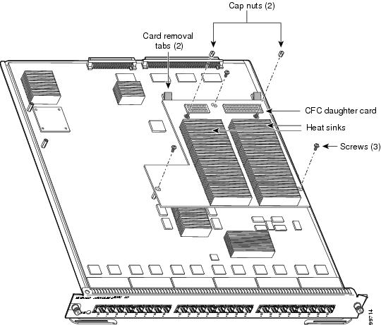
Step 4![]() Use a Phillips-head screwdriver to remove the installation hardware, which consists of three securing screws and the two cap nuts. (See Figure 1.)
Use a Phillips-head screwdriver to remove the installation hardware, which consists of three securing screws and the two cap nuts. (See Figure 1.)
Figure 1 CFC Daughter Card Installation Hardware
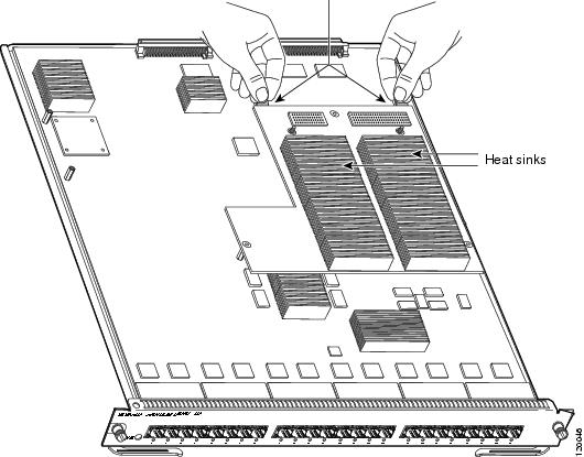
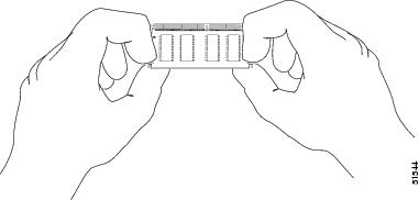
Step 5![]() To unseat the CFC daughter card from the Ethernet module, hold each tab at the rear of the CFC daughter card between your thumb and index finger, and gently press down on both tabs until the connectors are unseated. (See Figure 2.)
To unseat the CFC daughter card from the Ethernet module, hold each tab at the rear of the CFC daughter card between your thumb and index finger, and gently press down on both tabs until the connectors are unseated. (See Figure 2.)

Figure 2 Unseating the CFC Daughter Card Connectors
Step 6![]() Gently lift the CFC daughter card with both hands and remove the CFC daughter card from the module.
Gently lift the CFC daughter card with both hands and remove the CFC daughter card from the module.
Step 7![]() Place the CFC daughter card on an antistatic mat, antistatic foam pad, or in an antistatic bag.
Place the CFC daughter card on an antistatic mat, antistatic foam pad, or in an antistatic bag.
Step 8![]() Proceed to the “Installing the DFC3B and DFC3C Daughter Cards” section.
Proceed to the “Installing the DFC3B and DFC3C Daughter Cards” section.
Removing the DFC3 Daughter Card
This section contains two DFC3 daughter card removal procedures. The first procedure describes how to remove the DFC3 daughter card from modules that are not equipped with a stiffener bracket. The second procedure describes how to remove the DFC daughter card from early versions of the WS-X6748-GE-TX Ethernet module that are equipped with a stiffener bracket.
Note![]() Only some versions of the WS-X6748-GE-TX Ethernet module are equipped with a stiffener bracket.
Only some versions of the WS-X6748-GE-TX Ethernet module are equipped with a stiffener bracket.
Removing the DFC3 Daughter Card from Modules without Stiffener Brackets
Warning![]() During this procedure, wear grounding wrist straps to avoid ESD damage to the card. Do not directly touch the backplane with your hand or any metal tool, or you could shock yourself. Statement 94
During this procedure, wear grounding wrist straps to avoid ESD damage to the card. Do not directly touch the backplane with your hand or any metal tool, or you could shock yourself. Statement 94
To remove the DFC3 daughter card from modules that are not equipped with a stiffener bracket, follow these steps:
Step 1![]() Attach an ESD grounding strap to your wrist and to ground.
Attach an ESD grounding strap to your wrist and to ground.
If you are unsure about the correct way to attach an ESD grounding strap, refer to the “Attaching Your ESD Grounding Strap” section for instructions.
Step 2![]() Remove the Ethernet module from the chassis.
Remove the Ethernet module from the chassis.
If you are unsure about the correct procedure for removing a module from the switch chassis, refer to the “Removing an Ethernet Module from the Chassis” section for removal instructions.
Step 3![]() Place the Ethernet module on an antistatic mat with the front of the module facing toward you.
Place the Ethernet module on an antistatic mat with the front of the module facing toward you.
Step 4![]() If your DFC daughter card has a small metal installation bracket as shown in Figure 3, use a No.1 Phillips-head screwdriver to remove the two cap nuts and the one screw securing the bracket. Set them aside with the bracket. If there is no bracket, just remove the two cap nuts and the one screw.
If your DFC daughter card has a small metal installation bracket as shown in Figure 3, use a No.1 Phillips-head screwdriver to remove the two cap nuts and the one screw securing the bracket. Set them aside with the bracket. If there is no bracket, just remove the two cap nuts and the one screw.
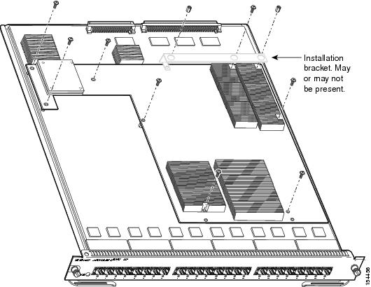
Step 5![]() Remove the remaining installation hardware. (See Figure 3.)
Remove the remaining installation hardware. (See Figure 3.)
Note![]() The installation hardware shown in Figure 3 is for a DFC3B or DFC3BXL daughter card. The installation hardware for a DFC3C or a DFC3CXL daughter card consists of 6 screws, 2 cap nuts, and 1 standoff.
The installation hardware shown in Figure 3 is for a DFC3B or DFC3BXL daughter card. The installation hardware for a DFC3C or a DFC3CXL daughter card consists of 6 screws, 2 cap nuts, and 1 standoff.
Figure 3 Removing the DFC Daughter Card Installation Hardware
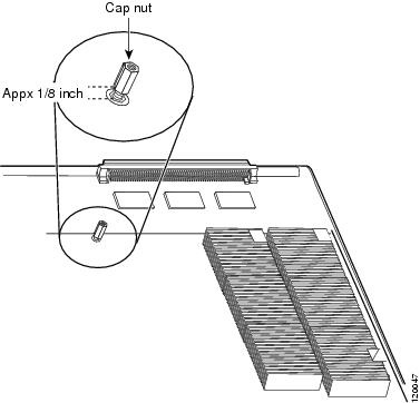
Step 6![]() Partially reinstall the cap nut, rotating about 3 turns so that there is a space of about 1/8 inch (3 mm) between the bottom of the cap nut and the top of the DFC3 daughter card, as shown in Figure 4. The cap nut acts as a stop when you unseat the daughter card connector so that the DFC3 daughter card does not move horizontally and cause damage to the base board.
Partially reinstall the cap nut, rotating about 3 turns so that there is a space of about 1/8 inch (3 mm) between the bottom of the cap nut and the top of the DFC3 daughter card, as shown in Figure 4. The cap nut acts as a stop when you unseat the daughter card connector so that the DFC3 daughter card does not move horizontally and cause damage to the base board.
Figure 4 Partially Installing the Cap Nut
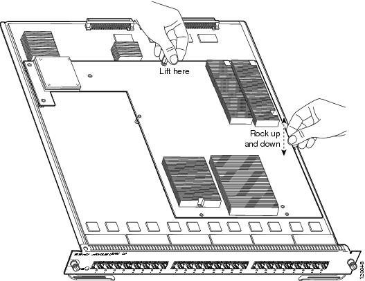
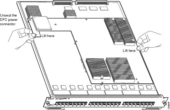
Step 7![]() With your left hand, lift slightly at the location shown in Figure 5. While lifting with your left hand, rock the DFC3 daughter card up and down with your right hand, no more than half an inch in either direction, to unseat the DFC3 daughter card from the module.
With your left hand, lift slightly at the location shown in Figure 5. While lifting with your left hand, rock the DFC3 daughter card up and down with your right hand, no more than half an inch in either direction, to unseat the DFC3 daughter card from the module.
Figure 5 Unseat the DFC3 Daughter Card from the Module
Step 8![]() Remove the one cap nut.
Remove the one cap nut.
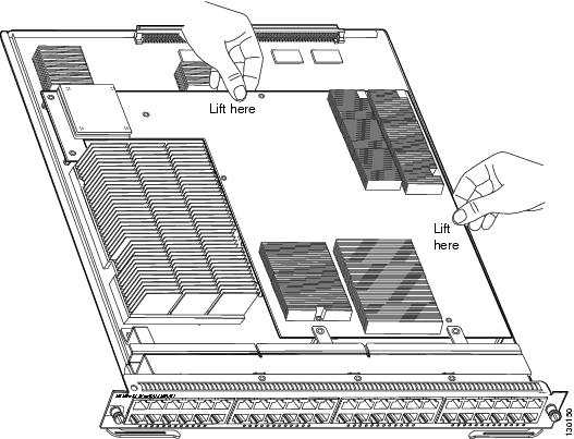
Step 9![]() Holding the DFC3 daughter card with both hands, gently lift it straight up from the module. (See Figure 6.) Immediately place the DFC3 daughter card on an antistatic mat, antistatic foam pad, or in an antistatic bag.
Holding the DFC3 daughter card with both hands, gently lift it straight up from the module. (See Figure 6.) Immediately place the DFC3 daughter card on an antistatic mat, antistatic foam pad, or in an antistatic bag.
Figure 6 Removing the DFC3 Daughter Card from the Module
Removing the DFC3 Daughter Card from WS-X6748-GE-TX Modules Equipped with a Stiffener Bracket
Some early versions of the WS-X6748-GE-TX Ethernet modules have a stiffener bracket mounted across the top front part of the module. A modified procedure to remove the DFC daughter card from WS-X6748-GE-TX Ethernet modules equipped with a stiffener bracket is included.
Warning![]() During this procedure, wear grounding wrist straps to avoid ESD damage to the card. Do not directly touch the backplane with your hand or any metal tool, or you could shock yourself. Statement 94
During this procedure, wear grounding wrist straps to avoid ESD damage to the card. Do not directly touch the backplane with your hand or any metal tool, or you could shock yourself. Statement 94
To remove a DFC3 daughter card from a WS-X6748-GE-TX Ethernet module that is equipped with a stiffener bracket, follow these steps:
Step 1![]() Attach an ESD grounding strap to your wrist and to ground.
Attach an ESD grounding strap to your wrist and to ground.
If you are unsure about the correct way to attach an ESD grounding strap, refer to the “Attaching Your ESD Grounding Strap” section for instructions.
Step 2![]() Remove the WS-X6748-GE-TX Ethernet module from the Catalyst 6500 series switch.
Remove the WS-X6748-GE-TX Ethernet module from the Catalyst 6500 series switch.
If you are unsure about the correct procedure for removing a module from the switch chassis, refer to the “Removing and Installing Ethernet Modules in the Chassis” section for removal instructions.
Step 3![]() Place the module on an antistatic mat or antistatic foam with the front of the module facing toward you.
Place the module on an antistatic mat or antistatic foam with the front of the module facing toward you.
Step 4![]() If your DFC daughter card has a small metal installation bracket as shown in Figure 7, use a No.1 Phillips-head screwdriver to remove the two cap nuts and the one screw securing the bracket. Set them aside with the bracket. If there is no installation bracket, remove the two cap nuts and the one screw.
If your DFC daughter card has a small metal installation bracket as shown in Figure 7, use a No.1 Phillips-head screwdriver to remove the two cap nuts and the one screw securing the bracket. Set them aside with the bracket. If there is no installation bracket, remove the two cap nuts and the one screw.
Step 5![]() Use a Phillips-head screwdriver to remove the remaining installation hardware. (See Figure 7.)
Use a Phillips-head screwdriver to remove the remaining installation hardware. (See Figure 7.)
Figure 7 Removing the Installation Hardware (DFC3B/DFC3BXL Shown) (WS-X6748-GE-TX Equipped with a Front Stiffener Bracket)

Note![]() The two screws securing the DFC3 daughter card that pass through the front stiffener bracket tabs are longer than the remaining DFC installation screws.
The two screws securing the DFC3 daughter card that pass through the front stiffener bracket tabs are longer than the remaining DFC installation screws.
Step 6![]() With your left hand, lift slightly at the location shown in Figure 8, and gently rock the DFC3 daughter card up and down to unseat the daughter card from the module connectors.
With your left hand, lift slightly at the location shown in Figure 8, and gently rock the DFC3 daughter card up and down to unseat the daughter card from the module connectors.
Figure 8 Unseating the DFC Connectors (WS-X6748-GE-TX Equipped with a Front Stiffener Bracket)
Step 7![]() Holding the DFC3 daughter card with both hands, carefully lift the back end of the DFC3 daughter card up slightly to clear the module connectors, and then carefully slide the DFC3 daughter card out from under the two front stiffener bracket tabs. Lift the DFC3 daughter card straight up from the module (see Figure 9) and immediately place the removed DFC3 daughter card on an antistatic mat, antistatic foam pad, or in an antistatic bag.
Holding the DFC3 daughter card with both hands, carefully lift the back end of the DFC3 daughter card up slightly to clear the module connectors, and then carefully slide the DFC3 daughter card out from under the two front stiffener bracket tabs. Lift the DFC3 daughter card straight up from the module (see Figure 9) and immediately place the removed DFC3 daughter card on an antistatic mat, antistatic foam pad, or in an antistatic bag.
Figure 9 Removing the DFC3 Daughter Card (WS-X6748-GE-TX Equipped with a Front Stiffener Bracket)

Upgrading the Ethernet Module Memory
When you upgrade your Ethernet module with either a DFC3BXL or DFC3CXL daughter card, you must also install a 1-GB memory upgrade (part number MEM-XCEF720-1GB) on the Ethernet module. This 1-GB memory upgrade is included with your DFC3BXL or DFC3CXL upgrade kit and installs on the Ethernet module in a small-outline dual-inline memory module (SODIMM) chip socket located underneath the DFC daughter card.
Note![]() You must perform the memory upgrade procedure after you remove the CFC or the DFC daughter card from the Ethernet module and before you install either the DFC3BXL or DFC3CXL daughter card upgrade.
You must perform the memory upgrade procedure after you remove the CFC or the DFC daughter card from the Ethernet module and before you install either the DFC3BXL or DFC3CXL daughter card upgrade.
Removing the Memory Module
Warning![]() During this procedure, wear grounding wrist straps to avoid ESD damage to the card. Do not directly touch the backplane with your hand or any metal tool, or you could shock yourself. Statement 94
During this procedure, wear grounding wrist straps to avoid ESD damage to the card. Do not directly touch the backplane with your hand or any metal tool, or you could shock yourself. Statement 94
To remove the existing memory module from the Ethernet module, follow these steps:
Step 1![]() Attach an ESD grounding strap to your wrist and to ground.
Attach an ESD grounding strap to your wrist and to ground.
If you are unsure about the correct way to attach an ESD grounding strap, refer to the “Attaching Your ESD Grounding Strap” section for instructions.
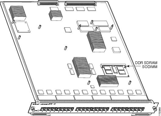
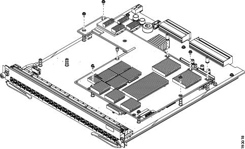
Step 2![]() Locate the memory module on the Ethernet module. (See Figure 10.)
Locate the memory module on the Ethernet module. (See Figure 10.)
Figure 10 Location of the Memory Module on a WS-X67xx Module
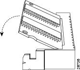
Step 3![]() Release the two spring clips on either side of the memory module to release it from the socket. (See Figure 11Figure 11.)
Release the two spring clips on either side of the memory module to release it from the socket. (See Figure 11Figure 11.)
Figure 11 Releasing the Memory Module Spring Clips
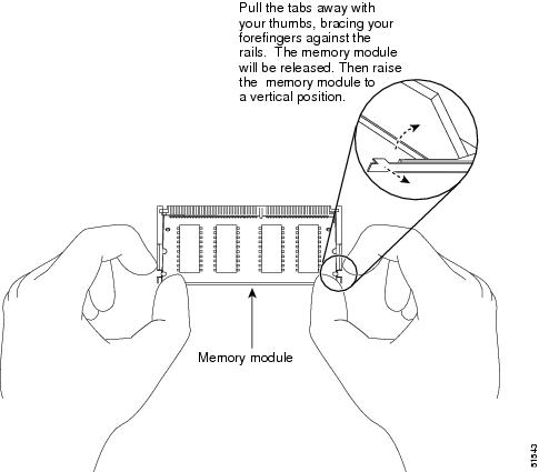
Step 4![]() Grasp the edges of the memory module with your thumb and forefinger, and gently pull the memory module completely out of the socket.
Grasp the edges of the memory module with your thumb and forefinger, and gently pull the memory module completely out of the socket.
Figure 12 Handling a Memory Module
Step 5![]() Immediately place the old memory module in an antistatic bag to protect it from ESD damage.
Immediately place the old memory module in an antistatic bag to protect it from ESD damage.
Installing the 1-GB Memory Module Upgrade
To install the 1-GB memory module on the Ethernet module, follow these steps:
Step 1![]() Verify that an ESD grounding strap is still securely attached to your wrist and to a proper earth ground.
Verify that an ESD grounding strap is still securely attached to your wrist and to a proper earth ground.
If you are unsure about the correct way to attach an ESD grounding strap, refer to the “Attaching Your ESD Grounding Strap” section for instructions.
Step 2![]() Remove the 1-GB memory module from the antistatic shipping bag.
Remove the 1-GB memory module from the antistatic shipping bag.
Step 3![]() Hold the sides of the 1-GB memory module between your thumbs and forefingers with the component side up and with the connector edge (the metal fingers) facing away from you. (See Figure 12.)
Hold the sides of the 1-GB memory module between your thumbs and forefingers with the component side up and with the connector edge (the metal fingers) facing away from you. (See Figure 12.)
Step 4![]() Tilt the 1-GB memory module to approximately the same angle as the socket, and insert the connector edge of the memory module into the socket.
Tilt the 1-GB memory module to approximately the same angle as the socket, and insert the connector edge of the memory module into the socket.
Step 5![]() Press the front edge of the 1-GB memory module down until both spring clips on the socket engage the sides of the memory module securing the memory module in place. (See Figure 13.)
Press the front edge of the 1-GB memory module down until both spring clips on the socket engage the sides of the memory module securing the memory module in place. (See Figure 13.)
Figure 13 Installing the SODIMM
Step 6![]() After the memory module is installed, check that both spring clips are fully engaged. If they are not, the memory module is not seated properly. If the memory module appears misaligned, carefully remove it and reseat it in the socket. Push the memory module firmly back into the socket until the spring clips snap into place.
After the memory module is installed, check that both spring clips are fully engaged. If they are not, the memory module is not seated properly. If the memory module appears misaligned, carefully remove it and reseat it in the socket. Push the memory module firmly back into the socket until the spring clips snap into place.
Installing the DFC3B and DFC3C Daughter Cards
This section contains two DFC3 installation procedures:
- Installing the DFC3B, DFC3BXL, DFC3C, and DFC3CXL Daughter Cards on Ethernet Modules without Stiffener Brackets
- Installing the DFC3B, DFC3BXL DFC3C, and DFC3CXL Daughter Cards on Ethernet Modules Equipped with a Stiffener Bracket
The first procedure describes how to install the DFC3 daughter card on Ethernet modules that are not equipped with a stiffener bracket. The second procedure describes how to install the DFC daughter cards on early versions of the WS-X6748-GE-TX Ethernet module that are equipped with stiffener brackets.
Note![]() If you are installing either a DFC3BXL or DFC3CXL daughter card, you must also upgrade the Ethernet module memory to 1 GB. You must perform this memory upgrade procedure before you install the DFC3BXL or DFC3CXL daughter card.
If you are installing either a DFC3BXL or DFC3CXL daughter card, you must also upgrade the Ethernet module memory to 1 GB. You must perform this memory upgrade procedure before you install the DFC3BXL or DFC3CXL daughter card.
Note![]() Not all WS-X6748-GE-TX Ethernet modules will have the stiffener bracket installed.
Not all WS-X6748-GE-TX Ethernet modules will have the stiffener bracket installed.
Installing the DFC3B, DFC3BXL, DFC3C, and DFC3CXL Daughter Cards on Ethernet Modules without Stiffener Brackets
Warning![]() During this procedure, wear grounding wrist straps to avoid ESD damage to the card. Do not directly touch the backplane with your hand or any metal tool, or you could shock yourself. Statement 94
During this procedure, wear grounding wrist straps to avoid ESD damage to the card. Do not directly touch the backplane with your hand or any metal tool, or you could shock yourself. Statement 94
To install the DFC daughter cards on Ethernet modules that do not have stiffener brackets, follow these steps:
Step 1![]() Attach an ESD grounding strap to your wrist and to ground.
Attach an ESD grounding strap to your wrist and to ground.
If you are unsure about the correct way to attach an ESD grounding strap, refer to the “Attaching Your ESD Grounding Strap” section for instructions.
Step 2![]() Remove the new DFC3 daughter card from the antistatic bag and the installation hardware from the packaging.
Remove the new DFC3 daughter card from the antistatic bag and the installation hardware from the packaging.
Note![]() The DFC3 daughter card is designed to be installed on different modules; therefore, there may be more mounting holes on the DFC3 daughter card than there are standoffs on the module. Not all mounting holes on the DFC3 daughter card are used in all installations. Visually verify that there are standoffs beneath the mounting holes before installing the installation hardware.
The DFC3 daughter card is designed to be installed on different modules; therefore, there may be more mounting holes on the DFC3 daughter card than there are standoffs on the module. Not all mounting holes on the DFC3 daughter card are used in all installations. Visually verify that there are standoffs beneath the mounting holes before installing the installation hardware.
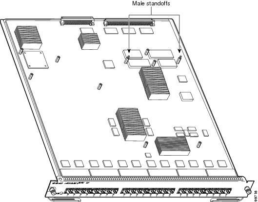
Step 3![]() Align the mounting holes on the DFC3 daughter card (see Figure 14) with the male standoffs on the module. (See Figure 15.) Make sure that the remaining mounting holes on the DFC3 daughter card are aligned with the remaining standoffs on the module.
Align the mounting holes on the DFC3 daughter card (see Figure 14) with the male standoffs on the module. (See Figure 15.) Make sure that the remaining mounting holes on the DFC3 daughter card are aligned with the remaining standoffs on the module.
Figure 14 Mounting Holes on the DFC3 Daughter Card
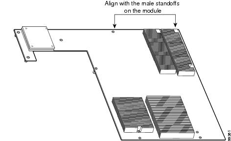
Figure 15 Male Standoff Locations on the WS-X67 xx Modules
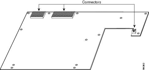
Step 4![]() Ensure that the connectors on the DFC3 are aligned with the connectors on the module. Figure 16 shows the connectors on the underside of the DFC3.
Ensure that the connectors on the DFC3 are aligned with the connectors on the module. Figure 16 shows the connectors on the underside of the DFC3.
Figure 16 DFC3 Daughter Card Connectors (Underside of DFC Daughter Card Shown)
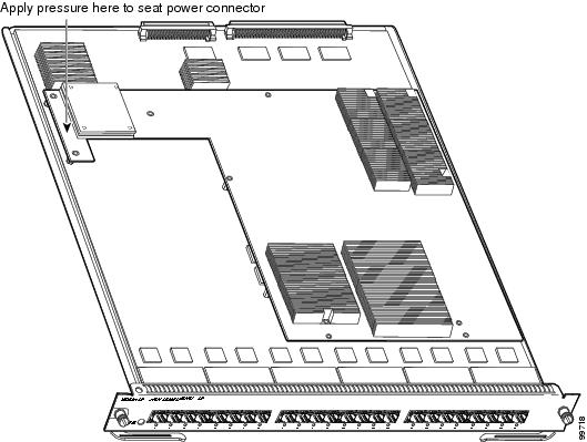
Step 5![]() Apply pressure to the area shown in Figure 17 to seat the power connector.
Apply pressure to the area shown in Figure 17 to seat the power connector.
Figure 17 Seating the Power Connector
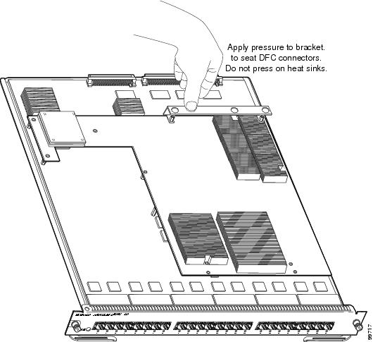
Step 6![]() Position the installation bracket over the two male standoffs at the back of the DFC daughter card. Apply pressure only to the top of the bracket to fully seat the DFC3 daughter card on the module as shown in Figure 18.
Position the installation bracket over the two male standoffs at the back of the DFC daughter card. Apply pressure only to the top of the bracket to fully seat the DFC3 daughter card on the module as shown in Figure 18.
Figure 18 Seating the DFC3 Daughter Card on the Module
Step 7![]() Use a Phillips-head screwdriver to install the installation hardware:
Use a Phillips-head screwdriver to install the installation hardware:
a.![]() For the DCFCB and the DFC3BXL daughter cards, install the 8 screws and the 2 standoffs. (See Figure 19.)
For the DCFCB and the DFC3BXL daughter cards, install the 8 screws and the 2 standoffs. (See Figure 19.)
b.![]() For the DFC3C and the DFC3CXL daughter cards, install the 6 screws, 2 cap nuts, and the 1 standoff. (See Figure 20.)
For the DFC3C and the DFC3CXL daughter cards, install the 6 screws, 2 cap nuts, and the 1 standoff. (See Figure 20.)
Note![]() You should visually verify that there are standoffs beneath the mounting holes before installing the installation hardware.
You should visually verify that there are standoffs beneath the mounting holes before installing the installation hardware.
Figure 19 Installing the Installation Hardware (DFC3B and DFC3BXL)
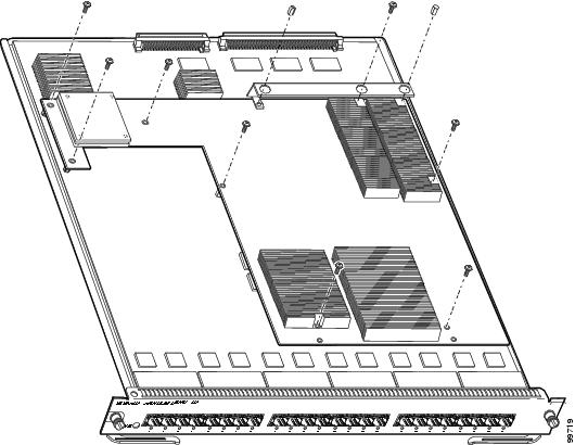
Figure 20 Installing the Installation Hardware (DFC3C and DFC3CXL)
Step 8![]() Reinstall the Ethernet module in the chassis.
Reinstall the Ethernet module in the chassis.
If you are unsure about the correct procedure for installing an Ethernet module in the switch chassis, refer to the “Removing and Installing Ethernet Modules in the Chassis” section for installation instructions.
Installing the DFC3B, DFC3BXL DFC3C, and DFC3CXL Daughter Cards on Ethernet Modules Equipped with a Stiffener Bracket
Some early versions of the WS-X6748-GE-TX Ethernet module have a stiffener bracket mounted across the top front part of the module. This stiffener bracket requires a modified procedure to install the DFC3 daughter card.
Warning![]() During this procedure, wear grounding wrist straps to avoid ESD damage to the card. Do not directly touch the backplane with your hand or any metal tool, or you could shock yourself. Statement 94
During this procedure, wear grounding wrist straps to avoid ESD damage to the card. Do not directly touch the backplane with your hand or any metal tool, or you could shock yourself. Statement 94
To install the DFC daughter card on an early version of the WS-X6748-GE-TX Ethernet module that is equipped with a stiffener bracket, follow these steps:
Step 1![]() Attach an ESD grounding strap to your wrist and to ground.
Attach an ESD grounding strap to your wrist and to ground.
If you are unsure about the correct way to attach an ESD grounding strap, refer to “Attaching Your ESD Grounding Strap” section for instructions.
Step 2![]() Remove the new DFC3 daughter card from the antistatic bag and the installation hardware from the bag.
Remove the new DFC3 daughter card from the antistatic bag and the installation hardware from the bag.
Note![]() The DFC3 daughter card is designed to be installed on different modules; therefore, there may be more mounting holes on the DFC3 daughter card than there are standoffs on the module. Not all mounting holes on the DFC3 daughter card are used in all installations. Visually verify that there are standoffs beneath the mounting holes before installing the installation hardware.
The DFC3 daughter card is designed to be installed on different modules; therefore, there may be more mounting holes on the DFC3 daughter card than there are standoffs on the module. Not all mounting holes on the DFC3 daughter card are used in all installations. Visually verify that there are standoffs beneath the mounting holes before installing the installation hardware.
Step 3![]() Position the DFC3 daughter card over the Ethernet module, and slightly tilt the DFC3 daughter card so that the back end will clear the module connectors.
Position the DFC3 daughter card over the Ethernet module, and slightly tilt the DFC3 daughter card so that the back end will clear the module connectors.
Step 4![]() Carefully slide the DFC3 under the two stiffener bracket tabs. (See Figure 21.) Verify that the DFC daughter card is under the two stiffener bracket tabs.
Carefully slide the DFC3 under the two stiffener bracket tabs. (See Figure 21.) Verify that the DFC daughter card is under the two stiffener bracket tabs.
Step 5![]() Align the mounting holes on the DFC3 daughter card with the male standoffs on the module. (See Figure 21.) Make sure that the remaining mounting holes on the DFC3 daughter card are aligned with the remaining standoffs.
Align the mounting holes on the DFC3 daughter card with the male standoffs on the module. (See Figure 21.) Make sure that the remaining mounting holes on the DFC3 daughter card are aligned with the remaining standoffs.
Note![]() You should visually verify that there are standoffs beneath the mounting holes before installing the installation hardware.
You should visually verify that there are standoffs beneath the mounting holes before installing the installation hardware.
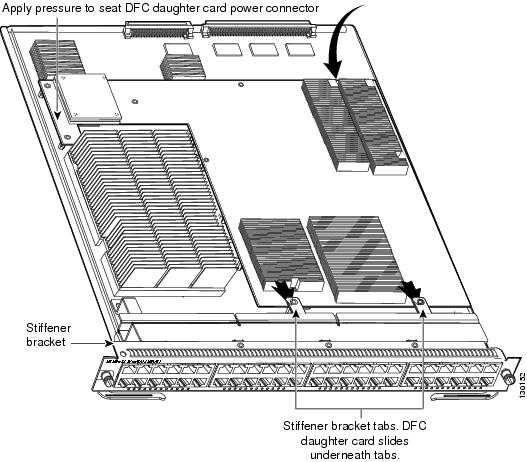
Step 6![]() Press down on the edge of the DFC3 daughter card (see Figure 21) to seat the DFC3 daughter card power connector to the module power connector.
Press down on the edge of the DFC3 daughter card (see Figure 21) to seat the DFC3 daughter card power connector to the module power connector.
Figure 21 Seating the DFC Daughter Card Power Connector (WS-X6748-GE-TX Equipped with a Front Stiffener Bracket)
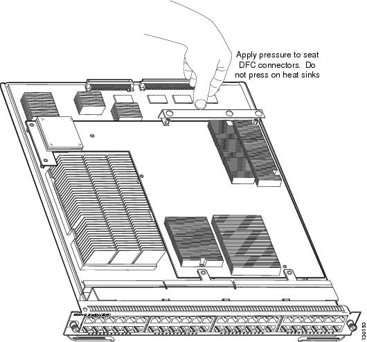
Step 7![]() Position the installation bracket over the two standoffs and press down only on the top of the bracket to seat the DFC3 daughter card connectors on the module connectors. (See Figure 22.)
Position the installation bracket over the two standoffs and press down only on the top of the bracket to seat the DFC3 daughter card connectors on the module connectors. (See Figure 22.)
Figure 22 Seating the DFC3 on the Module (WS-X6748-GE-TX Equipped with a Front Stiffener Bracket)
Step 8![]() Secure the DFC3 daughter card to the module through the stiffener bracket with the two long screws that you previously removed.
Secure the DFC3 daughter card to the module through the stiffener bracket with the two long screws that you previously removed.
Step 9![]() Install the remainder of the screws and the cap nuts to fully attach the DFC3 daughter card to the module:
Install the remainder of the screws and the cap nuts to fully attach the DFC3 daughter card to the module:
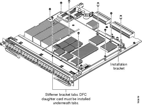
a.![]() For the DFC3B and DFC3BXL daughter cards, install the remaining 6 screws and 2 cap nuts. (See Figure 23.)
For the DFC3B and DFC3BXL daughter cards, install the remaining 6 screws and 2 cap nuts. (See Figure 23.)
b.![]() For the DFC3C and DFC3CXL daughter cards, install the remaining 4 screws, 2 cap nuts, and 1 standoff. (See Figure 24.)
For the DFC3C and DFC3CXL daughter cards, install the remaining 4 screws, 2 cap nuts, and 1 standoff. (See Figure 24.)
Figure 23 Installing the DFC3B and DFC3BXL Installation Hardware (WS-X6748-GE-TX Equipped with a Front Stiffener Bracket)

Figure 24 Installing the DFC3C and DFC3CXL Installation Hardware (WS-X6748-GE-TX Equipped with a Front Stiffener Bracket)
Step 10![]() Reinstall the Ethernet module in the chassis.
Reinstall the Ethernet module in the chassis.
If you are unsure about the correct procedure for installing the Ethernet module in the switch chassis, refer to the “Installing an Ethernet Module in the Chassis” section for installation instructions.
Removing and Installing Ethernet Modules in the Chassis
This section describes how to correctly remove and install an Ethernet module in a Catalyst 6500 series switch chassis slot.
Warning![]() Invisible laser radiation may be emitted from disconnected fibers or connectors. Do not stare into beams or view directly with optical instruments. Statement 272
Invisible laser radiation may be emitted from disconnected fibers or connectors. Do not stare into beams or view directly with optical instruments. Statement 272
Removing an Ethernet Module from the Chassis
To remove an Ethernet module from the chassis, perform these steps:
Step 1![]() Disconnect any network interface cables attached to the Ethernet module.
Disconnect any network interface cables attached to the Ethernet module.
Step 2![]() Attach an ESD grounding strap to your wrist and to a proper ground.
Attach an ESD grounding strap to your wrist and to a proper ground.
If you are unsure about the correct way to attach an ESD grounding strap, refer to the “Attaching Your ESD Grounding Strap” section for instructions.
Step 3![]() Verify that the captive installation screws on all of the modules in the chassis are tight. This step ensures that the space created by the removed module is maintained.
Verify that the captive installation screws on all of the modules in the chassis are tight. This step ensures that the space created by the removed module is maintained.
Note![]() If the captive installation screws are loose, the electromagnetic interference (EMI) gaskets on the installed modules expand and push the modules toward the open slot, which reduces the opening size and makes it difficult to reinstall the module.
If the captive installation screws are loose, the electromagnetic interference (EMI) gaskets on the installed modules expand and push the modules toward the open slot, which reduces the opening size and makes it difficult to reinstall the module.
Step 4![]() Loosen the two captive installation screws on the Ethernet module.
Loosen the two captive installation screws on the Ethernet module.
Step 5![]() Depending on the orientation of the slots in the chassis (horizontal or vertical), perform one of the following two sets of substeps:
Depending on the orientation of the slots in the chassis (horizontal or vertical), perform one of the following two sets of substeps:
a.![]() Place your thumbs on the left and right ejector levers located on the left and right sides of the module faceplate, and simultaneously rotate the levers outward to unseat the Ethernet module from the chassis backplane connector.
Place your thumbs on the left and right ejector levers located on the left and right sides of the module faceplate, and simultaneously rotate the levers outward to unseat the Ethernet module from the chassis backplane connector.
b.![]() Grasp the front edge of the Ethernet module and slide the module part of the way out of the slot. Place your other hand under the Ethernet module to support the weight of the module. Do not touch the module circuitry.
Grasp the front edge of the Ethernet module and slide the module part of the way out of the slot. Place your other hand under the Ethernet module to support the weight of the module. Do not touch the module circuitry.
c.![]() Place the removed Ethernet module on a properly grounded antistatic mat or antistatic foam.
Place the removed Ethernet module on a properly grounded antistatic mat or antistatic foam.
a.![]() Place your thumbs on the ejector levers located at the top and bottom of the Ethernet module, and simultaneously rotate the levers outward to unseat the Ethernet module from the chassis backplane connector.
Place your thumbs on the ejector levers located at the top and bottom of the Ethernet module, and simultaneously rotate the levers outward to unseat the Ethernet module from the chassis backplane connector.
b.![]() Grasp the front edge of the Ethernet module and slide the module part of the way out of the slot. Place your other hand under the Ethernet module to support the weight of the module. Do not touch the module circuitry.
Grasp the front edge of the Ethernet module and slide the module part of the way out of the slot. Place your other hand under the Ethernet module to support the weight of the module. Do not touch the module circuitry.
c.![]() Place the removed Ethernet module on a properly grounded antistatic mat or antistatic foam.
Place the removed Ethernet module on a properly grounded antistatic mat or antistatic foam.
Installing an Ethernet Module in the Chassis
Warning![]() Invisible laser radiation may be emitted from disconnected fibers or connectors. Do not stare into beams or view directly with optical instruments. Statement 1051
Invisible laser radiation may be emitted from disconnected fibers or connectors. Do not stare into beams or view directly with optical instruments. Statement 1051
To install a module in the chassis, perform these steps:
Step 1![]() Verify that an ESD grounding strap is attached to your wrist and to proper ground.
Verify that an ESD grounding strap is attached to your wrist and to proper ground.
If you are unsure about the correct way to attach an ESD grounding strap, refer to the “Attaching Your ESD Grounding Strap” section for instructions.
Step 2![]() Verify that the captive installation screws are tightened on all of the modules installed in the chassis. This step assures that the EMI gaskets on all of the installed modules are fully compressed in order to maximize the opening space for the Ethernet module.
Verify that the captive installation screws are tightened on all of the modules installed in the chassis. This step assures that the EMI gaskets on all of the installed modules are fully compressed in order to maximize the opening space for the Ethernet module.
Note![]() If the captive installation screws are loose, the electromagnetic interference (EMI) gaskets on the installed modules expand and push the modules toward the open slot, which reduces the opening size and makes it difficult to reinstall the module.
If the captive installation screws are loose, the electromagnetic interference (EMI) gaskets on the installed modules expand and push the modules toward the open slot, which reduces the opening size and makes it difficult to reinstall the module.
Step 3![]() Fully open both ejector levers on the Ethernet module. (See Figure 25.)
Fully open both ejector levers on the Ethernet module. (See Figure 25.)
Step 4![]() Depending on the orientation of the slots in the chassis (horizontal or vertical), perform one of the following two sets of substeps:
Depending on the orientation of the slots in the chassis (horizontal or vertical), perform one of the following two sets of substeps:
a.![]() Position the Ethernet module in the slot. (See Figure 25.) Make sure that you align the edges of the module carrier with the slot guides on each side of the slot.
Position the Ethernet module in the slot. (See Figure 25.) Make sure that you align the edges of the module carrier with the slot guides on each side of the slot.
b.![]() Carefully slide the Ethernet module into the slot until the EMI gasket along the top edge of the module makes contact with the module in the slot above it and both ejector levers have engaged and closed to approximately 45 degrees with respect to the Ethernet module faceplate. (See Figure 26.)
Carefully slide the Ethernet module into the slot until the EMI gasket along the top edge of the module makes contact with the module in the slot above it and both ejector levers have engaged and closed to approximately 45 degrees with respect to the Ethernet module faceplate. (See Figure 26.)
c.![]() Using the thumb and forefinger of each hand, grasp the two ejector levers and press down to create a small (0.040 inch [1 mm]) gap between the module’s EMI gasket and the module above it. (See Figure 26.)
Using the thumb and forefinger of each hand, grasp the two ejector levers and press down to create a small (0.040 inch [1 mm]) gap between the module’s EMI gasket and the module above it. (See Figure 26.)
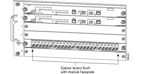
d.![]() While gently pressing down, simultaneously close the left and right ejector levers to fully seat the Ethernet module in the chassis backplane connector. The ejector levers are fully closed when they are flush with the module faceplate. (See Figure 27.)
While gently pressing down, simultaneously close the left and right ejector levers to fully seat the Ethernet module in the chassis backplane connector. The ejector levers are fully closed when they are flush with the module faceplate. (See Figure 27.)
Note![]() Failure to fully seat the module in the chassis backplane connector can result in error messages.
Failure to fully seat the module in the chassis backplane connector can result in error messages.
e.![]() Tighten the two captive installation screws on the Ethernet module.
Tighten the two captive installation screws on the Ethernet module.
Note![]() Make sure that the ejector levers are fully closed before tightening the captive installation screws.
Make sure that the ejector levers are fully closed before tightening the captive installation screws.
f.![]() Verify that the Ethernet module STATUS LED is lit. Check the STATUS LED periodically. If the STATUS LED changes from orange to green, the module has successfully completed the boot process and is now online. If the STATUS LED remains orange or turns red, the module has not successfully completed the boot process and may have encountered an error.
Verify that the Ethernet module STATUS LED is lit. Check the STATUS LED periodically. If the STATUS LED changes from orange to green, the module has successfully completed the boot process and is now online. If the STATUS LED remains orange or turns red, the module has not successfully completed the boot process and may have encountered an error.
Figure 25 Positioning the Module in a Horizontal Slot Chassis
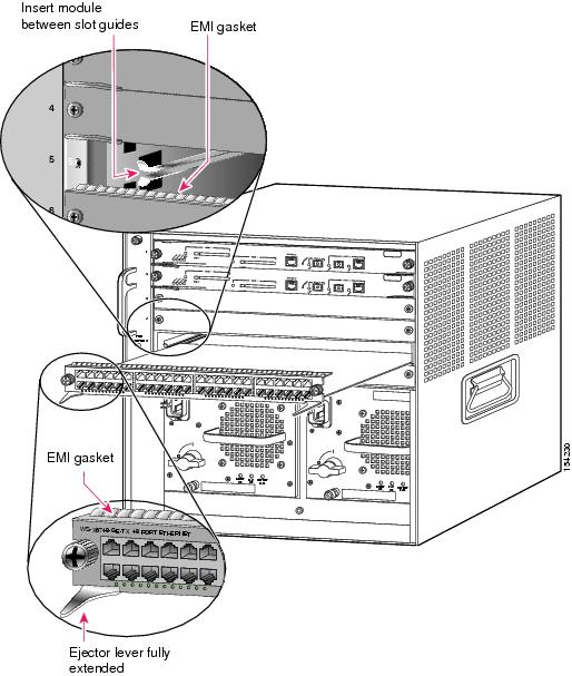
Figure 26 Clearing the EMI Gasket in a Horizontal Slot Chassis
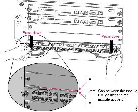
Figure 27 Ejector Lever Closure in a Horizontal Slot Chassis
a.![]() Position the Ethernet module in the slot. (See Figure 28.) Make sure that you align the edges of the module carrier with the slot guides on the top and bottom of the chassis slot.
Position the Ethernet module in the slot. (See Figure 28.) Make sure that you align the edges of the module carrier with the slot guides on the top and bottom of the chassis slot.
b.![]() Carefully slide the Ethernet module into the slot until the EMI gasket along the right edge of the module faceplate makes contact with the module in the slot adjacent to it and both ejector levers have closed to approximately 45 degrees with respect to the Ethernet module faceplate. (See Figure 29.)
Carefully slide the Ethernet module into the slot until the EMI gasket along the right edge of the module faceplate makes contact with the module in the slot adjacent to it and both ejector levers have closed to approximately 45 degrees with respect to the Ethernet module faceplate. (See Figure 29.)
c.![]() Using the thumb and forefinger of each hand, grasp the two ejector levers and exert a slight pressure to the left, deflecting the module approximately 0.040 inches (1 mm) to create a small gap between the module’s EMI gasket and the module adjacent to it. (See Figure 29.)
Using the thumb and forefinger of each hand, grasp the two ejector levers and exert a slight pressure to the left, deflecting the module approximately 0.040 inches (1 mm) to create a small gap between the module’s EMI gasket and the module adjacent to it. (See Figure 29.)
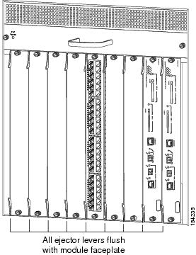
d.![]() While gently pressing on the ejector levers, simultaneously close them to fully seat the Ethernet module in the chassis backplane connector. The ejector levers are fully closed when they are flush with the Ethernet module faceplate. (See Figure 30.)
While gently pressing on the ejector levers, simultaneously close them to fully seat the Ethernet module in the chassis backplane connector. The ejector levers are fully closed when they are flush with the Ethernet module faceplate. (See Figure 30.)
e.![]() Tighten the two captive installation screws on the Ethernet module.
Tighten the two captive installation screws on the Ethernet module.
Note![]() Make sure that the ejector levers are fully closed before tightening the captive installation screws.
Make sure that the ejector levers are fully closed before tightening the captive installation screws.
f.![]() Verify that the Ethernet module STATUS LED is lit. Check the STATUS LED periodically. If the STATUS LED changes from orange to green, the module has successfully completed the boot process and is now online. If the STATUS LED remains orange or turns red, the module has not successfully completed the boot process and may have encountered an error.
Verify that the Ethernet module STATUS LED is lit. Check the STATUS LED periodically. If the STATUS LED changes from orange to green, the module has successfully completed the boot process and is now online. If the STATUS LED remains orange or turns red, the module has not successfully completed the boot process and may have encountered an error.
Figure 28 Positioning the Module in a Vertical Slot Chassis
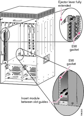
Figure 29 Clearing the EMI Gasket in a Vertical Slot Chassis
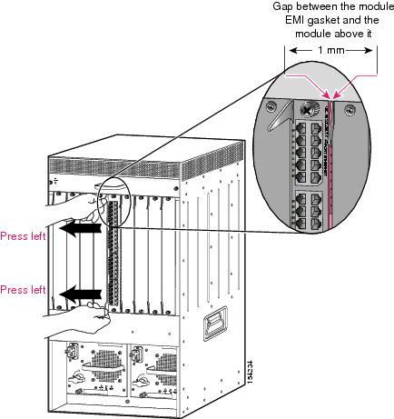
Figure 30 Ejector Lever Closure in a Vertical Slot Chassis
Attaching Your ESD Grounding Strap
Electrostatic discharge (ESD) damage, which can occur when modules or other FRUs are improperly handled, results in intermittent or complete failures. Modules consist of printed circuit boards that are fixed in metal carriers. Electromagnetic interference (EMI) shielding and connectors are integral components of the carrier. Although the metal carrier helps to protect the board from ESD, always use an ESD grounding strap attached to a properly grounded bare metal surface when handling modules.
Follow these guidelines for preventing ESD damage:
- Always use an ESD wrist strap and ensure that it makes maximum contact with bare skin. ESD grounding straps are available with banana plugs, metal spring clips, or alligator clips. All Catalyst 6500 series chassis are equipped with a banana plug connector (identified by the ground symbol next to the connector) somewhere on the chassis front panel.
–![]() If you have an older Catalyst 6500 series chassis equipped with a plastic banana plug connector, we recommend that you use either the supplied ESD grounding wrist strap (with a metal clip) or an ESD grounding wrist strap equipped with an alligator clip.
If you have an older Catalyst 6500 series chassis equipped with a plastic banana plug connector, we recommend that you use either the supplied ESD grounding wrist strap (with a metal clip) or an ESD grounding wrist strap equipped with an alligator clip.
–![]() If you have a newer Catalyst 6500 series chassis that has a bare metal hole as the banana plug connector (also identified by the ground symbol next to the connector), we recommend that you use a personal ESD grounding strap equipped with a banana plug.
If you have a newer Catalyst 6500 series chassis that has a bare metal hole as the banana plug connector (also identified by the ground symbol next to the connector), we recommend that you use a personal ESD grounding strap equipped with a banana plug.
- If you choose to use the disposable ESD wrist strap supplied with the chassis or an ESD wrist strap equipped with an alligator clip, you must attach the system ground lug to the chassis in order to provide a proper grounding point for the ESD wrist strap.
Note![]() This system ground is also referred to as the network equipment building system (NEBS) ground.
This system ground is also referred to as the network equipment building system (NEBS) ground.
- If your chassis does not have the system ground attached, you must install the system ground lug. Refer to the online Catalyst 6500 Series Switches Installation Guide for the procedure.
Note![]() You do not need to attach a supplemental system ground wire to the system ground lug; the lug provides a direct path to the bare metal of the chassis.
You do not need to attach a supplemental system ground wire to the system ground lug; the lug provides a direct path to the bare metal of the chassis.
After you install the system ground lug, follow these steps to correctly attach the ESD wrist strap:
Step 1![]() Attach the ESD wrist strap to bare skin as follows:
Attach the ESD wrist strap to bare skin as follows:
a.![]() If you are using the ESD wrist strap supplied with the FRUs, open the wrist strap package and unwrap the ESD wrist strap. Place the black conductive loop over your wrist and tighten the strap so that it makes good contact with your bare skin.
If you are using the ESD wrist strap supplied with the FRUs, open the wrist strap package and unwrap the ESD wrist strap. Place the black conductive loop over your wrist and tighten the strap so that it makes good contact with your bare skin.
b.![]() If you are using an ESD wrist strap equipped with an alligator clip, open the package and remove the ESD wrist strap. Locate the end of the wrist strap that attaches to your body and secure it to your bare skin.
If you are using an ESD wrist strap equipped with an alligator clip, open the package and remove the ESD wrist strap. Locate the end of the wrist strap that attaches to your body and secure it to your bare skin.
Step 2![]() Grasp the spring or alligator clip on the ESD wrist strap and momentarily touch the clip to a bare metal spot (unpainted surface) on the rack. We recommend that you touch the clip to an unpainted rack rail so that any built-up static charge is then safely dissipated to the entire rack.
Grasp the spring or alligator clip on the ESD wrist strap and momentarily touch the clip to a bare metal spot (unpainted surface) on the rack. We recommend that you touch the clip to an unpainted rack rail so that any built-up static charge is then safely dissipated to the entire rack.
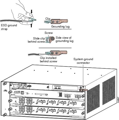
Step 3![]() Attach either the spring clip or the alligator clip to the ground lug screw as follows (See Figure 31):
Attach either the spring clip or the alligator clip to the ground lug screw as follows (See Figure 31):
a.![]() If you are using the ESD wrist strap that is supplied with the FRUs, squeeze the spring clip jaws open, position the spring clip to one side of the system ground lug screw head, and slide the spring clip over the lug screw head so that the spring clip jaws close behind the lug screw head.
If you are using the ESD wrist strap that is supplied with the FRUs, squeeze the spring clip jaws open, position the spring clip to one side of the system ground lug screw head, and slide the spring clip over the lug screw head so that the spring clip jaws close behind the lug screw head.
Note![]() The spring clip jaws do not open wide enough to fit directly over the head of the lug screw or the lug barrel.
The spring clip jaws do not open wide enough to fit directly over the head of the lug screw or the lug barrel.
b.![]() If you are using an ESD wrist strap that is equipped with an alligator clip, attach the alligator clip directly over the head of the system ground lug screw or to the system ground lug barrel.
If you are using an ESD wrist strap that is equipped with an alligator clip, attach the alligator clip directly over the head of the system ground lug screw or to the system ground lug barrel.
Figure 31 Attaching the ESD Wrist Strap Clip to the System Ground Lug Screw
When handling modules, follow these additional guidelines:
- Handle carriers by available handles or edges only; avoid touching the printed circuit boards or connectors.
- Place a removed component board-side-up on an antistatic surface or in a static-shielding container. If you plan to return the component to the factory, immediately place it in a static-shielding container.
- Never attempt to remove the printed circuit board from the metal carrier.
Obtaining Documentation and Submitting a Service Request
For information on obtaining documentation, submitting a service request, and gathering additional information, see the monthly What’s New in Cisco Product Documentation, which also lists all new and revised Cisco technical documentation, at:
http://www.cisco.com/en/US/docs/general/whatsnew/whatsnew.html
Subscribe to the What’s New in Cisco Product Documentation as a Really Simple Syndication (RSS) feed and set content to be delivered directly to your desktop using a reader application. The RSS feeds are a free service and Cisco currently supports RSS Version 2.0.
Cisco and the Cisco Logo are trademarks of Cisco Systems, Inc. and/or its affiliates in the U.S. and other countries. A listing of Cisco's trademarks can be found at www.cisco.com/go/trademarks. Third party trademarks mentioned are the property of their respective owners. The use of the word partner does not imply a partnership relationship between Cisco and any other company. (1005R)
 Feedback
Contact Cisco
- Open a Support Case

- (Requires a Cisco Service Contract)