Catalyst 6503 Switch Installation Note
Available Languages
Table Of Contents
Catalyst 6503 Switch Installation Note
Preparing to Install the Switch
Rack Dimension and Clearance Guidelines
Installing the Switch Chassis in the Rack
Installing the Power Supplies in the Switch Chassis
Installing an AC-Input Power Supply
Installing a DC-Input Power Supply
Attaching the Interface Cables
Connecting the Supervisor Engine Console Port
Connecting the Supervisor Engine Uplink Ports
Verifying Switch Chassis Installation
Obtaining Documentation and Submitting a Service Request
Catalyst 6503 Switch Installation Note
Product Number: WS-C6503(=)
This publication contains the procedures for installing the Catalyst 6503 switch.

Note
For the latest Catalyst 6500 series switch and Cisco 7600 series Internet Router software release notes, including caveats and updates, refer to the release notes for the latest maintenance release in your software release. You can access release notes at the World Wide Web locations listed in the "Obtaining Documentation" section
Contents
This publication contains these sections:
•
•
•
•
Overview
The Catalyst 6503 switch chassis has three horizontal slots that are numbered from top to bottom. (See Figure 1.)
Figure 1 Catalyst 6503 Switch — Front View
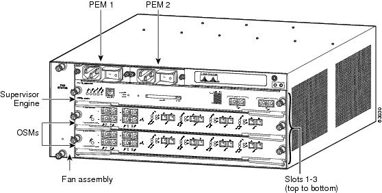
Slot 1 is reserved for the supervisor engine, which provides switching, local and remote management, and multiple gigabit uplink interfaces.
Slot 2 can contain an additional redundant supervisor engine, which can act as a backup if the first supervisor engine fails. If a redundant supervisor engine is not required, slot 2 is available for an OSM or other supported Catalyst 6500 series modules.
For a detailed description of supervisor engine operation in a redundant configuration, refer to the Catalyst 6500 Series Software Configuration Guide.
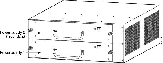
The power supplies are installed from the rear of the chassis. A maximum of two 950W power supplies can be installed. (See Figure 2.)
Figure 2 Catalyst 6503 Switch — Rear View
The Catalyst 6503 switch supports the following:
•
–
–
Note
Note
•
Note
Note
•
•
Bandwidth and Port Density
Table 1 lists the bandwidth and port densities of the Catalyst 6503 switch.
Specifications
The Catalyst 6503 switch specifications are provided in Table 2.
Table 2 Catalyst 6503 Switch Specifications
Temperature, ambient operating
32°F (0°C) to 104°F (40°C)
Temperature, ambient nonoperating and storage
-40°F (-40°C) to 158°F (70°C)
Humidity (RH), ambient (noncondensing) operating
10% to 90%
Humidity (RH), ambient (noncondensing) nonoperating and storage
5% to 95%
Altitude, operating
Sea level to 6500 feet (2000 m)
Dimensions (H x W x D)
7 x 17.37 x 21.75 inches (17.78 x 44.12 x 55.25 cm). Chassis requires 4 RU1 .
Weight
Chassis only: 28.5 lb (12.93 kg)
Chassis fully configured with 1 supervisor engine, 2 modules, 2 AC-input PEMs, and 2 AC-input power supplies: 83 lb (37.65 kg)
950W AC- or DC-input power supply. An optional second power supply can be installed in the chassis.
200 lfm2 through system fan assembly
1 RU = rack units
2 lfm = linear feet per minute
Chassis Components
This section describes the major hardware components for the Catalyst 6503 switch:
Fan Assembly
The system fan assembly, located in the chassis, provides cooling air for the supervisor engine and the switching modules. Figure 3 shows the direction of airflow into and out of the switch. Sensors on the supervisor engine monitor the internal air temperatures. If the air temperature exceeds a preset threshold, the environmental monitor displays warning messages.
Figure 3 Chassis Internal Airflow
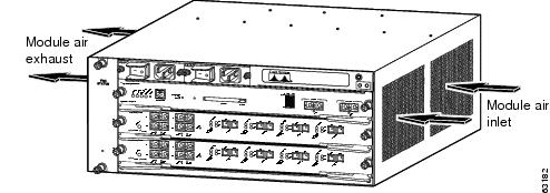
If an individual fan within the assembly fails, the FAN STATUS LED turns red.
Note
Power Supplies
The Catalyst 6503 switch supports either the 950W AC-input or 950W DC-input power supply (PWR-950-AC or PWR-950-DC).
The Catalyst 6503 supports redundant AC-input and DC-input power supplies.
The power supply (see Figure 4) has no external connectors but uses a power entry module (PEM), located on the front of the chassis, to connect the site power source to the power supply. For more information on the PEM, see the "Power Entry Module (PEM)" section.
Figure 4 950W Power Supply
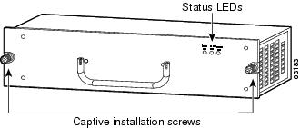
Both the AC-input and DC-input power supplies support redundancy. When power is removed from one supply, the redundant power feature causes the second supply to produce full power.
For complete power supply specifications, see Table 3.
Load Sharing
When you install and turn on two power supplies, each of the power supplies provides approximately half of the total amount of power required to operate the system. If one power supply fails, the second power supply immediately assumes full power to maintain uninterrupted system operation. Installing the second power supply automatically enables load sharing and fault tolerance; no software configuration is required.
Note
For information about the power management feature and individual module power consumption, refer to the Catalyst 6500 Series Software Configuration Guide.
Environmental Monitoring of the Power Supply
The environmental monitoring and reporting functions allow you to maintain normal system operation by resolving adverse environmental conditions prior to loss of operation.
The power supplies monitor their own internal temperature and voltages, and in the event of excessive internal temperature, the power supply will shut down to prevent damage. When the power supply returns to a safe operating temperature, it will restart. In the event of an abnormal voltage on one or more outputs of the power supplies, the OUTPUT FAIL LED will light. Substantial overvoltage conditions can lead to a power supply shutdown.
The power supply front panel LEDs are described in Table 4.
For more information about the environmental monitoring feature, refer to the Catalyst 6500 Series Software Configuration Guide.
Power Supply Cooling
Each power supply has a built-in fan; air enters from the right of the fan and exits through the left. The Catalyst 6503 power supplies are self cooling to 77°F (25°C) but require additional airflow provided by the system fan module to operate over the full temperature range.
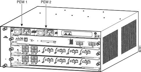
Power Entry Module (PEM)
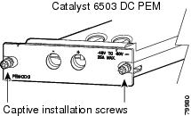
The AC-input PEM (shown in Figure 5) and the DC-input PEM (shown in Figure 6) provide input power connections on the front of the switch chassis to connect the site power source to the power supply. In addition to providing an input power connection, each PEM also has an illuminated power switch (AC-input only), current protection, surge and EMI suppression, and filtering functions.
Figure 5 AC-Input PEM
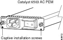
Figure 6 DC-Input PEM
Safety Overview
Safety warnings appear throughout this publication in procedures that, if performed incorrectly, may cause harm to you. A warning symbol precedes each warning statement.

Warning
Preparing to Install the Switch
This section includes guidelines that you need to follow before installing the switch.
Rack Dimension and Clearance Guidelines
Before installing the chassis, ensure that the equipment rack complies with these guidelines:
•
•
•

Caution
The installation hardware is not suitable for use with racks with obstructions (such as power strips) that could impair access to field-replaceable units (FRUs).
Power Connection Guidelines
This section provides important guidelines for connecting the Catalyst 6503 AC-input and DC-input power supplies to the site power source. Follow these guidelines when preparing your site for the installation:
•
•
•
•
AC-Input Systems
Basic guidelines for AC-input systems include the following:
•
•
•
•
Figure 7 shows the different styles of power cord plugs that are available for North America or various international locales for the 950W power supply. Table 5 lists the AC-input power cord options and Cisco product numbers.
Figure 7 AC Power Cord Plugs and Appliance Coupler for the 950W Power Supply

DC-Powered Systems
Basic guidelines for DC-powered systems include the following:
•
•
•
•
•
Site Preparation Checklist
Table 6 lists the site planning activities that you should perform prior to installing the Catalyst 6503 switch. Completing each activity helps ensure a successful installation.
Installing the Switch
Warning
Warning
This section contains the procedures you need to follow to install the Catalyst 6503 switch.
Unpacking the Switch

Tip
Perform the following to check the contents of the shipping container:
•
–
–
•
Required Tools
These tools and equipment are required to install the switch chassis in the rack:
•
•
•
Installing the Brackets
The chassis is shipped with the mounting brackets installed on the front of the chassis. These brackets can be installed on the rear of the chassis.
To install the brackets on the rear of the chassis, perform these steps:
Step 1
Figure 8 Installing the L-Brackets on the Catalyst 6503 Switch
Step 2
Step 3
Step 4
Installing the Switch Chassis in the Rack
Warning
To install the switch chassis in the equipment rack, perform these steps:
Step 1
a.
b.
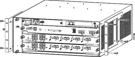
Step 2
Figure 9 Installing the Switch Chassis in the Rack
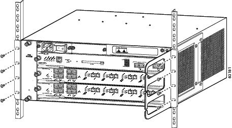
Step 3
Step 4
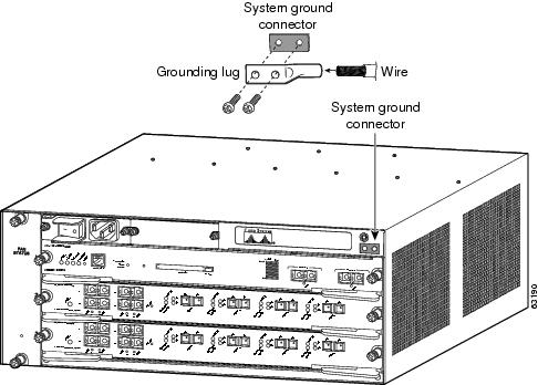
System Ground Connection
This section describes how to connect a system (earth) ground to the Catalyst 6503 switch chassis.
Note
Two threaded M4 holes are provided on the chassis frame to attach the ground cable. (See Figure 10 for the system ground location.)
Required Tools and Equipment
To connect the system ground, you need the following tools and materials:
•
•
Note
•
•
•
•
Figure 10 System Ground Location
Connecting the System Ground
You must complete this procedure before connecting system power or turning on the Catalyst 6503 switch.
To attach the grounding lug and cable to the grounding pad, perform these steps:
Step 1
Step 2
Step 3
Step 4
Step 5
Step 6
Step 7
Installing the Power Supplies in the Switch Chassis
The 950W power supply (AC-input or DC-input) is shipped separately from the chassis. Remove the power supply from its shipping packaging.
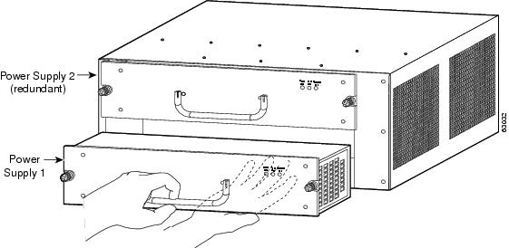
Installing an AC-Input Power Supply
Follow these steps to install an AC-input power supply:
Step 1
Step 2
Step 3
Figure 11 Installing an AC-Input Power Supply
Step 4
Warning
Figure 12 Power Supply Captive Installation Screws
Step 5
Step 6
Caution
Figure 13 PEM Location
Step 7
Step 8
•
•
•
Installing a DC-Input Power Supply
Warning
Follow these steps to install a DC-input power supply:
Step 1
Step 2
Figure 14 Installing a DC-Input Power Supply
Step 3
Warning
Figure 15 Power Supply Captive Installation Screws
Caution
Step 4
Figure 16 DC-Input PEM
Step 5
Step 6
•
•
Step 7
Caution
Step 8
Step 9
•
•
•
Attaching the Interface Cables
This section provides general information on attaching interface cables to the supervisor engines and to the modules.
Depending on the modules you have installed in your chassis, you will have different styles of connectors to attach.
Note
Connecting the Supervisor Engine Console Port
This section describes how to connect to the supervisor engine console port from a terminal or modem.
The console port on the supervisor engine allows you to perform the following functions:
•
•
•
•
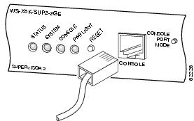
The console port, located on the front panel of the supervisor engine, is shown in Figure 17.
Figure 17 Supervisor Engine Console Port Connector
Note
To connect a terminal to the console port using the cable and adapters provided, perform these steps:
Step 1
Step 2
Step 3
Step 4
•
•
•
•
To connect a terminal using a Catalyst 5000 family Supervisor Engine III console cable, perform these steps:
Step 1
Step 2
Step 3
Step 4
•
•
•
•
To connect a modem to the console port, perform these steps:
Step 1
Step 2
Step 3
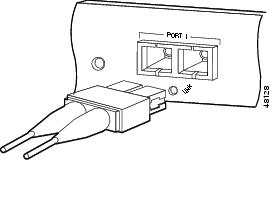
Connecting the Supervisor Engine Uplink Ports
This section describes how to connect to the supervisor engine uplink ports.
Warning
Note
To connect to the supervisor engine uplink ports, perform these steps:
Step 1
Step 2
Figure 18 Connecting the Supervisor Engine Uplink Ports
Note
Note
Verifying Switch Chassis Installation
After you finish connecting the modules, you need to verify that the modules, power supplies, power entry modules (PEMs), and fan assembly are correctly and securely installed. To verify the chassis installation, perform these steps:
Step 1
Step 2
Note
Warning
Step 3
Step 4
Warning
Note
Related Documentation
For additional information on the Catalyst 6503 switch, refer to these publications:
•
•
•
•
•
Obtaining Documentation and Submitting a Service Request
For information on obtaining documentation, submitting a service request, and gathering additional information, see the monthly What's New in Cisco Product Documentation, which also lists all new and revised Cisco technical documentation, at:
http://www.cisco.com/en/US/docs/general/whatsnew/whatsnew.html
Subscribe to the What's New in Cisco Product Documentation as a Really Simple Syndication (RSS) feed and set content to be delivered directly to your desktop using a reader application. The RSS feeds are a free service and Cisco currently supports RSS Version 2.0.
This document is to be used in conjunction with the documents listed in the "Related Documentation" section.

Copyright © 2002, Cisco Systems, Inc.
All rights reserved.
 Feedback
Contact Cisco
- Open a Support Case

- (Requires a Cisco Service Contract)
This Document Applies to These Products
- Collaboration Endpoints - Retired Products
- Conferencing - Retired Products
- Contact Center - Retired Products
- Optical Networking - Retired Products
- Routers - Retired Products
- Security - Retired Products
- Servers - Unified Computing (UCS) Retired Products
- Storage Networking Retired Products
- Switches - Retired Products
- Video - Retired Products
- Wireless - Retired Products