Guest

Support

Catalyst 6000 Family MSFC2 Bootflash Device Upgrade Installation Note

Table Of Contents

Catalyst 6000 Family MSFC2 Bootflash Device Upgrade Installation Note

Contents

Required Tools

Safety Overview

Verifying the Bootflash Size

Catalyst Software

Cisco IOS Software

Removing the Supervisor Engine

Installing the Bootflash Device

Replacing the Supervisor Engine

Related Documentation

Obtaining Documentation

World Wide Web

Documentation CD-ROM

Ordering Documentation

Documentation Feedback

Obtaining Technical Assistance

Cisco.com

Technical Assistance Center

Cisco TAC Web Site

Cisco TAC Escalation Center


Catalyst 6000 Family MSFC2 Bootflash Device Upgrade Installation Note


Product Number:
WS-X6K-MSFC2-KIT=

This publication describes how to remove and install the bootflash device on the Catalyst 6000 family Multilayer Switch Feature Card 2 (MSFC2).

This installation upgrades the MSFC2 bootflash device from 16 MB to 32 MB.


Note A boot loader image and an IOS (c6msfc2) image are provided on the bootflash device.


Contents

This publication consists of these sections:

Required Tools

Safety Overview

Verifying the Bootflash Size

Removing the Supervisor Engine

Installing the Bootflash Device

Replacing the Supervisor Engine

Related Documentation

Obtaining Documentation

Obtaining Technical Assistance

Required Tools

The following tools are required to perform the installation:

Antistatic mat or foam pad to support the removed supervisor engine

3/16-inch flat-blade screwdriver for the captive installation screws on the supervisor engine

A wrist strap or other grounding device to prevent electrostatic discharge (ESD) damage

Refer to the Site Preparation and Safety Guide for ESD details including the locations of the ESD connectors on the Catalyst 6000 family switches.

Safety Overview

Safety warnings appear throughout this publication in procedures that may harm you if performed incorrectly. A warning symbol precedes each warning statement.

Warning This warning symbol means danger. You are in a situation that could cause bodily injury. Before you work on any equipment, be aware of the hazards involved with electrical circuitry and be familiar with standard practices for preventing accidents. To see translations of the warnings that appear in this publication, refer to the Regulatory Compliance and Safety Information document that accompanied this device.

Waarschuwing

Dit waarschuwingssymbool betekent gevaar. U verkeert in een situatie die lichamelijk letsel kan veroorzaken. Voordat u aan enige apparatuur gaat werken, dient u zich bewust te zijn van de bij elektrische schakelingen betrokken risico's en dient u op de hoogte te zijn van standaard maatregelen om ongelukken te voorkomen. Voor vertalingen van de waarschuwingen die in deze publicatie verschijnen, kunt u het document Regulatory Compliance and Safety Information (Informatie over naleving van veiligheids- en andere voorschriften) raadplegen dat bij dit toestel is ingesloten.

Varoitus

Tämä varoitusmerkki merkitsee vaaraa. Olet tilanteessa, joka voi johtaa ruumiinvammaan. Ennen kuin työskentelet minkään laitteiston parissa, ota selvää sähkökytkentöihin liittyvistä vaaroista ja tavanomaisista onnettomuuksien ehkäisykeinoista. Tässä julkaisussa esiintyvien varoitusten käännökset löydät laitteen mukana olevasta Regulatory Compliance and Safety Information -kirjasesta (määräysten noudattaminen ja tietoa turvallisuudesta).

Attention

Ce symbole d'avertissement indique un danger. Vous vous trouvez dans une situation pouvant causer des blessures ou des dommages corporels. Avant de travailler sur un équipement, soyez conscient des dangers posés par les circuits électriques et familiarisez-vous avec les procédures couramment utilisées pour éviter les accidents. Pour prendre connaissance des traductions d'avertissements figurant dans cette publication, consultez le document Regulatory Compliance and Safety Information (Conformité aux règlements et consignes de sécurité) qui accompagne cet appareil.

Warnung

Dieses Warnsymbol bedeutet Gefahr. Sie befinden sich in einer Situation, die zu einer Körperverletzung führen könnte. Bevor Sie mit der Arbeit an irgendeinem Gerät beginnen, seien Sie sich der mit elektrischen Stromkreisen verbundenen Gefahren und der Standardpraktiken zur Vermeidung von Unfällen bewußt. Übersetzungen der in dieser Veröffentlichung enthaltenen Warnhinweise finden Sie im Dokument Regulatory Compliance and Safety Information (Informationen zu behördlichen Vorschriften und Sicherheit), das zusammen mit diesem Gerät geliefert wurde.

Avvertenza

Questo simbolo di avvertenza indica un pericolo. La situazione potrebbe causare infortuni alle persone. Prima di lavorare su qualsiasi apparecchiatura, occorre conoscere i pericoli relativi ai circuiti elettrici ed essere al corrente delle pratiche standard per la prevenzione di incidenti. La traduzione delle avvertenze riportate in questa pubblicazione si trova nel documento Regulatory Compliance and Safety Information (Conformità alle norme e informazioni sulla sicurezza) che accompagna questo dispositivo.

Advarsel

Dette varselsymbolet betyr fare. Du befinner deg i en situasjon som kan føre til personskade. Før du utfører arbeid på utstyr, må du vare oppmerksom på de faremomentene som elektriske kretser innebærer, samt gjøre deg kjent med vanlig praksis når det gjelder å unngå ulykker. Hvis du vil se oversettelser av de advarslene som finnes i denne publikasjonen, kan du se i dokumentet Regulatory Compliance and Safety Information (Overholdelse av forskrifter og sikkerhetsinformasjon) som ble levert med denne enheten.

Aviso

Este símbolo de aviso indica perigo. Encontra-se numa situação que lhe poderá causar danos físicos. Antes de começar a trabalhar com qualquer equipamento, familiarize-se com os perigos relacionados com circuitos eléctricos, e com quaisquer práticas comuns que possam prevenir possíveis acidentes. Para ver as traduções dos avisos que constam desta publicação, consulte o documento Regulatory Compliance and Safety Information (Informação de Segurança e Disposições Reguladoras) que acompanha este dispositivo.

¡Advertencia!

Este símbolo de aviso significa peligro. Existe riesgo para su integridad física. Antes de manipular cualquier equipo, considerar los riesgos que entraña la corriente eléctrica y familiarizarse con los procedimientos estándar de prevención de accidentes. Para ver una traducción de las advertencias que aparecen en esta publicación, consultar el documento titulado Regulatory Compliance and Safety Information (Información sobre seguridad y conformidad con las disposiciones reglamentarias) que se acompaña con este dispositivo.

Varning!

Denna varningssymbol signalerar fara. Du befinner dig i en situation som kan leda till personskada. Innan du utför arbete på någon utrustning måste du vara medveten om farorna med elkretsar och känna till vanligt förfarande för att förebygga skador. Se förklaringar av de varningar som förkommer i denna publikation i dokumentet Regulatory Compliance and Safety Information (Efterrättelse av föreskrifter och säkerhetsinformation), vilket medföljer denna anordning.


Warning Only trained and qualified personnel should be allowed to install or replace this equipment.


Warning During this procedure, wear grounding wrist straps to avoid ESD damage to the card. Do not directly touch the backplane with your hand or any metal tool, or you could shock yourself.


Verifying the Bootflash Size

The following sections describe the procedures to determine the size of the MSFC2 bootflash device:

Catalyst Software

Cisco IOS Software

Catalyst Software


Note For information on accessing the MSFC2 from the switch, refer to Chapter 2, "Command-Line Interfaces," in the Catalyst 6000 Family Configuration Guide.


From the privileged EXEC router prompt, enter the dir bootflash: command to determine the size of the bootflash device installed on the MSFC2.

The following example shows a 16-MB bootflash device:

Router# dir bootflash:

Directory of bootflash:/
  1  -rw-     1599488   Nov 29 1999 11:12:29  c6msfc-boot-mz.120-7.XE.bin
15990784 bytes total (14391168 bytes free)

Cisco IOS Software

From the privileged EXEC prompt, enter the following commands to determine the size of the bootflash device installed on the MSFC2:

Command
Purpose

Router# dir bootflash:

Determine the size of the bootflash device on the active MSFC2.

Router# dir slavebootflash:

Determine the size of the bootflash device on the standby MSFC2.


The following example shows a 16-MB bootflash device:

Router# dir bootflash:

Directory of bootflash:/
  1  -rw-     1599488   Nov 29 1999 11:12:29  c6msfc-boot-mz.120-7.XE.bin
15990784 bytes total (14391168 bytes free)

Removing the Supervisor Engine

To install the bootflash device upgrade on the MSFC2, you must first remove the supervisor engine from the chassis.


Caution Always use an ESD wrist strap when handling modules or coming into contact with internal components.


Caution The supervisor engine is a required system component. If only one supervisor engine is present, removing it while the system is operating causes the system to halt.


Note When two supervisor engines are installed, hot swapping allows you to remove and replace one of the supervisor engines without turning off the system power.


Caution To avoid erroneous failure messages, note the current configuration of all interfaces before you remove or replace another switching module, and allow at least 15 seconds for the system to reinitialize after a module has been removed or replaced.

When removing the supervisor engine, use the ejector levers to ensure that the connector pins disconnect from the backplane properly. Any supervisor engine or switching module that is only partially connected to the backplane can disrupt the system. Detailed instructions for removing and installing modules are described in the Catalyst 6000 Family Module Installation Guide.

To remove a supervisor engine, perform these steps:


Step 1 If you do not plan to immediately reinstall the supervisor engine you are removing, disconnect any network interface cables attached to the uplink ports.

Step 2 Use a screwdriver to loosen the captive installation screws at the left and right sides of the supervisor engine (see Figure 1).

Figure 1 Ejector Levers and Captive Installation Screws
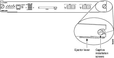
Step 3 Grasp the left and right ejector levers; simultaneously pull the left lever to the left and the right lever to the right to release the supervisor engine from the backplane connector.

Step 4 As you pull the supervisor engine out of the slot, place one of your hands under the carrier to support it. Avoid touching the supervisor engine itself.

Step 5 Carefully pull the supervisor engine straight out of the slot, keeping one hand under the carrier to guide it. Keep the supervisor engine at a 90-degree orientation to the backplane (horizontal to the floor).

Step 6 Place the removed supervisor engine on an antistatic mat or antistatic foam pad.


When you remove and replace the redundant supervisor engine, the system provides status messages on the console screen. The messages are for information only. For additional information, refer to the Catalyst 6000 Family Software Configuration Guide and Catalyst 6000 Family Command Reference publication.

Installing the Bootflash Device

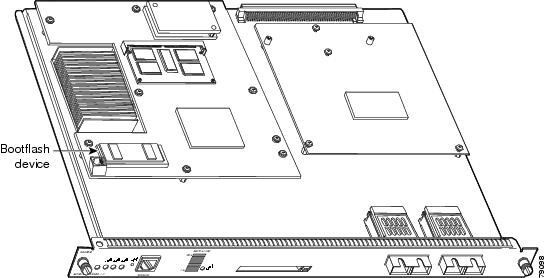
This section describes how to remove the existing bootflash device and replace it with the upgrade bootflash device. The bootflash device location is shown in Figure 2 for the MSFC2 shipped before November 2001 and Figure 3 for the MSFC2 shipped after November 2001.

Figure 2 MSFC2 Shipped Before November 2001—Bootflash Device Location

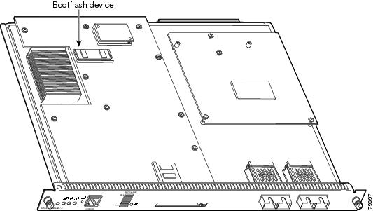
Figure 3 MSFC2 Shipped After November 2001—Bootflash Device Location

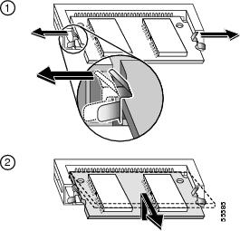
To upgrade the bootflash device from 16 MB to 32 MB, follow these steps:


Step 1 Pull the locking spring clips on both sides of the bootflash device SIMM holder outward and tilt the SIMM up and away from the clips (see Figure 4). Be careful not to break the clips on the SIMM connector.

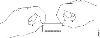
Figure 4 Removing and Installing the Bootflash Device SIMM

Step 2 Hold the SIMM by its edges and gently lift and remove it, placing it on an antistatic mat or foam. (See Figure 5.)

Figure 5 Handling a SIMM


Caution SIMMs are sensitive components that are susceptible to ESD damage. To prevent ESD damage, handle SIMMs by the edges only; avoid touching the memory modules, pins, or traces (the metal fingers along the connector edge of the SIMM). (See Figure 5.)

Step 3 Remove the upgrade SIMM from the antistatic container.

Step 4 Hold the SIMM by its edges. (See Figure 5.)

Step 5 Tilt the SIMM to approximately the same angle as the socket, and insert the connector edge into the socket. Note the notch (key) on the right connector edge of the SIMM. (See Figure 5.) This key assures correct orientation of the SIMM in the socket.


Caution When inserting the SIMM, use firm but not excessive pressure. If you damage a socket, you will have to return the MSFC2 to Cisco for repair.

Step 6 Press the SIMM down until it is secured by the spring clips. (See Figure 6.)

Figure 6 Installing the SIMM in the Socket
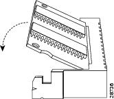
Step 7 When the SIMM is installed, check the two alignment holes and ensure that the spring retainer is visible. If it is not visible, the SIMM is not seated properly. If the SIMM appears misaligned, carefully remove it and reseat it in the socket. Push the SIMM firmly back into the socket until the retainer springs snap into place.


Replacing the Supervisor Engine

The ejector levers on the supervisor engine and switching modules align and seat the module connectors in the backplane (see Figure 1). If you fail to use the ejector levers to insert the supervisor engine, you can disrupt the order in which the pins contact the backplane. You must pull out the ejector levers as you slide the supervisor engine in. Detailed instructions for removing and installing the supervisor engine are described in the Catalyst 6000 Family Module Installation Guide.

To replace the supervisor engine, follow Step 1 through Step 6 in the "Removing the Supervisor Engine" section in reverse order. Note that the supervisor engine must go in slot 1 (if a second, redundant supervisor is installed, install it in slot 2).

Related Documentation

For additional information on Catalyst 6000 family switches and command-line interface (CLI) commands, refer to the following publications:

Regulatory Compliance and Safety Information for the Catalyst 6000 Family Switches

Catalyst 6000 Family Installation Guide

Catalyst 6000 Family Module Installation Guide

Catalyst 6000 Family Software Configuration Guide

Catalyst 6000 Family Command Reference

Catalyst 6000 Family IOS Software Configuration Guide

Catalyst 6000 Family IOS Command Reference

Site Preparation and Safety Guide

Obtaining Documentation

The following sections explain how to obtain documentation from Cisco Systems.

World Wide Web

You can access the most current Cisco documentation on the World Wide Web at the following URL:

http://www.cisco.com

Translated documentation is available at the following URL:

http://www.cisco.com/public/countries_languages.shtml

Documentation CD-ROM

Cisco documentation and additional literature are available in a Cisco Documentation CD-ROM package, which is shipped with your product. The Documentation CD-ROM is updated monthly and may be more current than printed documentation. The CD-ROM package is available as a single unit or through an annual subscription.

Ordering Documentation

Cisco documentation is available in the following ways:

Registered Cisco Direct Customers can order Cisco product documentation from the Networking Products MarketPlace:

http://www.cisco.com/cgi-bin/order/order_root.pl

Registered Cisco.com users can order the Documentation CD-ROM through the online Subscription Store:

http://www.cisco.com/go/subscription

Nonregistered Cisco.com users can order documentation through a local account representative by calling Cisco corporate headquarters (California, USA) at 408 526-7208 or, elsewhere in North America, by calling 800 553-NETS (6387).

Documentation Feedback

If you are reading Cisco product documentation on Cisco.com, you can submit technical comments electronically. Click Leave Feedback at the bottom of the Cisco Documentation home page. After you complete the form, print it out and fax it to Cisco at 408 527-0730.

You can e-mail your comments to bug-doc@cisco.com.

To submit your comments by mail, use the response card behind the front cover of your document, or write to the following address:

Cisco Systems
Attn: Document Resource Connection
170 West Tasman Drive
San Jose, CA 95134-9883

We appreciate your comments.

Obtaining Technical Assistance

Cisco provides Cisco.com as a starting point for all technical assistance. Customers and partners can obtain documentation, troubleshooting tips, and sample configurations from online tools by using the Cisco Technical Assistance Center (TAC) Web Site. Cisco.com registered users have complete access to the technical support resources on the Cisco TAC Web Site.

Cisco.com

Cisco.com is the foundation of a suite of interactive, networked services that provides immediate, open access to Cisco information, networking solutions, services, programs, and resources at any time, from anywhere in the world.

Cisco.com is a highly integrated Internet application and a powerful, easy-to-use tool that provides a broad range of features and services to help you to

Streamline business processes and improve productivity

Resolve technical issues with online support

Download and test software packages

Order Cisco learning materials and merchandise

Register for online skill assessment, training, and certification programs

You can self-register on Cisco.com to obtain customized information and service. To access Cisco.com, go to the following URL:

http://www.cisco.com

Technical Assistance Center

The Cisco TAC is available to all customers who need technical assistance with a Cisco product, technology, or solution. Two types of support are available through the Cisco TAC: the Cisco TAC Web Site and the Cisco TAC Escalation Center.

Inquiries to Cisco TAC are categorized according to the urgency of the issue:

Priority level 4 (P4)—You need information or assistance concerning Cisco product capabilities, product installation, or basic product configuration.

Priority level 3 (P3)—Your network performance is degraded. Network functionality is noticeably impaired, but most business operations continue.

Priority level 2 (P2)—Your production network is severely degraded, affecting significant aspects of business operations. No workaround is available.

Priority level 1 (P1)—Your production network is down, and a critical impact to business operations will occur if service is not restored quickly. No workaround is available.

Which Cisco TAC resource you choose is based on the priority of the problem and the conditions of service contracts, when applicable.

Cisco TAC Web Site

The Cisco TAC Web Site allows you to resolve P3 and P4 issues yourself, saving both cost and time. The site provides around-the-clock access to online tools, knowledge bases, and software. To access the Cisco TAC Web Site, go to the following URL:

http://www.cisco.com/tac

All customers, partners, and resellers who have a valid Cisco services contract have complete access to the technical support resources on the Cisco TAC Web Site. The Cisco TAC Web Site requires a Cisco.com login ID and password. If you have a valid service contract but do not have a login ID or password, go to the following URL to register:

http://www.cisco.com/register/

If you cannot resolve your technical issues by using the Cisco TAC Web Site, and you are a Cisco.com registered user, you can open a case online by using the TAC Case Open tool at the following URL:

http://www.cisco.com/tac/caseopen

If you have Internet access, it is recommended that you open P3 and P4 cases through the Cisco TAC Web Site.

Cisco TAC Escalation Center

The Cisco TAC Escalation Center addresses issues that are classified as priority level 1 or priority level 2; these classifications are assigned when severe network degradation significantly impacts business operations. When you contact the TAC Escalation Center with a P1 or P2 problem, a Cisco TAC engineer will automatically open a case.

To obtain a directory of toll-free Cisco TAC telephone numbers for your country, go to the following URL:

http://www.cisco.com/warp/public/687/Directory/DirTAC.shtml

Before calling, please check with your network operations center to determine the level of Cisco support services to which your company is entitled; for example, SMARTnet, SMARTnet Onsite, or Network Supported Accounts (NSA). In addition, please have available your service agreement number and your product serial number.