Table Of Contents
Catalyst 6500 Series Power over Ethernet Daughter Cards Field-Upgrade Installation Note
Statement 1071—Warning Definition
Removing the Ethernet Switching Module
Removing and Installing the WS-F6K-VPWR Inline-Power Daughter Card
Removing the WS-F6K-VPWR Inline-Power Daughter Card
Installing the WS-F6K-VPWR Inline-Power Daughter Card
Removing and Installing the WS-F6K-VPWR-GE Inline-Power Daughter Card
Removing the WS-F6K-VPWR-GE Inline-Power Daughter Card
Installing the WS-F6K-VPWR-GE Inline-Power Daughter Card
Removing and Installing the WS-F6K-GE48-AF Inline-Power Daughter Card
Removing the WS-F6K-GE48-AF Inline-Power Daughter Card
Installing the WS-F6K-GE48-AF Inline-Power Daughter Card
Removing and Installing the WS-F6K-FE48X2-AF Inline-Power Daughter Card
Removing the WS-F6K-FE48X2-AF Inline-Power Daughter Card
Installing the WS-F6K-FE48X2-AF Inline-Power Daughter Card
Removing and Installing the WS-F6K-48-AF Inline-Power Daughter Card
Removing the WS-F6K-48-AF Inline-Power Daughter Card
Installing the WS-F6K-48-AF Inline-Power Daughter Card
Installing the Ethernet Switching Module
Regulatory Standards Compliance
Statement 1001—Work During Lightning Activity
Statement 1030—Equipment Installation
Statement 1034—Backplane Voltage
Statement 1041—Disconnecting Telephone-Network Cables
Statement 1072—Shock Hazard from Interconnections
Cisco Product Security Overview
Reporting Security Problems in Cisco Products
Obtaining Technical Assistance
Cisco Technical Support Website
Definitions of Service Request Severity
Obtaining Additional Publications and Information
Catalyst 6500 Series Power over Ethernet Daughter Cards Field-Upgrade Installation Note
This publication describes how to install and remove the following Catalyst 6500 series Power over Ethernet (PoE) daughter cards. The PoE daughter cards and a brief description are listed in Table 1.
Note
The WS-F6K-VPWR and WS-F6K-VPWR-GE PoE daughter cards are not interchangeable between Ethernet modules.
Contents
This publication consists of these sections:
•
Removing the Ethernet Switching Module
•
Removing and Installing the WS-F6K-VPWR Inline-Power Daughter Card
•
Removing and Installing the WS-F6K-VPWR-GE Inline-Power Daughter Card
•
Removing and Installing the WS-F6K-GE48-AF Inline-Power Daughter Card
•
Removing and Installing the WS-F6K-FE48X2-AF Inline-Power Daughter Card
•
Removing and Installing the WS-F6K-48-AF Inline-Power Daughter Card
•
Installing the Ethernet Switching Module
•
Regulatory Standards Compliance
•
Cisco Product Security Overview
•
Obtaining Technical Assistance
•
Obtaining Additional Publications and Information
Note
For translations of the warnings in this publication, see the "Translated Safety Warnings" section.
Overview
The PoE daughter cards can be installed on select 10/100 and 10/100/1000 Ethernet switching modules in the field to upgrade the Ethernet switching modules to provide inline power for IP phones and other devices. Table 2 lists the PoE daughter cards, the Ethernet modules they are supported on, and the port power and port speed. Table 3 lists feature of the PoE daughter cards.
Warning
Only trained and qualified personnel should be allowed to install, replace, or service this equipment. Statement 1030
Safety Overview
Statement 1071—Warning Definition
Warning
Hazardous voltage or energy is present on the backplane when the system is operating. Use caution when servicing. Statement 1034
Removing the Ethernet Switching Module
This section describes how to remove an Ethenet module from the switch chassis.
Required Tools
The following tools are required to perform the PoE daughter card removal and installation procedures:
•
Number 2 Phillips screwdriver for the captive installation screws on the module on which the daughter card is to be removed or installed.
Note
We recommend that you use a Number 2 Phillips magnetic tip.
•
Magnetic-tip Number 1 Phillips screwdriver for the screws and cap nuts that fasten the daughter card to the Ethernet module.
•
Antistatic mat or antistatic foam.
•
Your own ESD-prevention equipment or the disposable grounding wrist strap included with all upgrade kits, field-replaceable units (FRUs), and spares.
Removing the Ethernet Switching Module
CautionDuring this procedure, wear grounding wrist straps to avoid ESD damage to the card.
Warning
Before opening the unit, disconnect the telephone-network cables to avoid contact with telephone-network voltages. Statement 1041
Warning
Do not work on the system or connect or disconnect cables during periods of lightning activity. Statement 1001
Warning
To avoid electric shock, do not connect safety extra-low voltage (SELV) circuits to telephone-network voltage (TNV) circuits. LAN ports contain SELV circuits, and WAN ports contain TNV circuits. Some LAN and WAN ports both use RJ-45 connectors. Use caution when connecting cables. Statement 1021
Warning
Voltages that present a shock hazard may exist on Power over Ethernet (PoE) circuits if interconnections are made using uninsulated exposed metal contacts, conductors, or terminals. Avoid using such interconnection methods, unless the exposed metal parts are located within a restricted access location and users and service people who are authorized within the restricted access location are made aware of the hazard. A restricted access area can be accessed only through the use of a special tool, lock and key or other means of security. Statement 1072
CautionTo prevent ESD damage, handle switching modules by the carrier edges only.
To remove the Ethernet switching module from the chassis, perform these steps:
Step 1
Disconnect any network interface cables attached to the module.
Step 2
Verify that the captive installation screws on all of the other modules in the chassis are tight. This step ensures that the slot opening space created by the removed module is maintained.
Note
If the captive installation screws are loose, the EMI gaskets on the installed modules will push the modules toward the open slot, reducing the opening size and making it difficult to reinstall the module.
Step 3
Loosen the two captive installation screws on the module to be removed.
Step 4
Depending on the orientation of the slots in the chassis (horizontal or vertical), perform one of the following two sets of steps:
Horizontal slots
a.
Place your thumbs on the left and right ejector levers and simultaneously rotate the levers outward to unseat the module from the backplane connector. (See Figure 1.)
b.
Grasp the front edge of the module and slide the module part of the way out of the slot. Place your other hand under the module to support the weight of the module. Do not touch the module circuitry. (See Figure 2.)
Figure 1 Opening the Ejector Levers (Horizontal Chassis Shown)
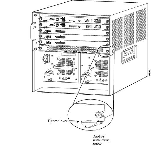
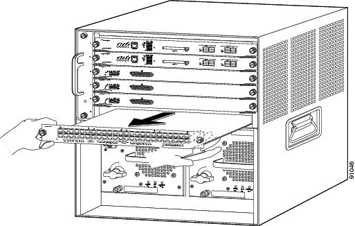
Figure 2 Removing the Module from the Chassis (Horizontal Chassis Shown)
Vertical slots
a.
Place your thumbs on the ejector levers located at the top and bottom of the module, and simultaneously rotate the levers outward to unseat the module from the backplane connector.
b.
Grasp the edges of the module, and slide the module straight out of the slot. Do not touch the module circuitry.
Step 5
Place the module on an antistatic mat or antistatic foam.
Step 6
You are now ready to remove or install your inline-power daughter card. Refer to Table 4 for a list of inline-power daughter cards and the related removal and installation procedures.
Table 4 Inline-Power Daughter Card Removal and Installation Procedures
Inline-Power Daughter Card Removal and Installation Procedure ReferenceWS-F6K-VPWR=
Removing and Installing the WS-F6K-VPWR Inline-Power Daughter Card
WS-F6K-VPWR-GE=
Removing and Installing the WS-F6K-VPWR-GE Inline-Power Daughter Card
WS-F6K-GE48-AF=
Removing and Installing the WS-F6K-GE48-AF Inline-Power Daughter Card
WS-F6K-FE48X2-AF=
Removing and Installing the WS-F6K-FE48X2-AF Inline-Power Daughter Card
WS-F6K-48-AF=
Removing and Installing the WS-F6K-48-AF Inline-Power Daughter Card
Step 7
After removing or installing your inline-power daughter card, go to the "Installing the Ethernet Switching Module" section.
Removing and Installing the WS-F6K-VPWR Inline-Power Daughter Card
The WS-F6K-VPWR inline-power daughter card is supported only on the following Ethernet modules:
•
WS-X6148-RJ-21
•
WS-X6148-RJ-45
•
WS-X6348-RJ-45
The WS-F6K-VPWR inline-power daughter card supports Cisco prestandard inline power; it does not support IEEE 802.3af.
Removing the WS-F6K-VPWR Inline-Power Daughter Card
To remove the WS-F6K-VPWR inline-power daughter card from the module, perform these steps:
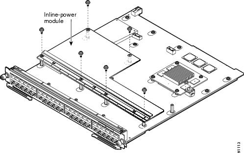
Step 1
Remove the six screws as shown in Figure 3.
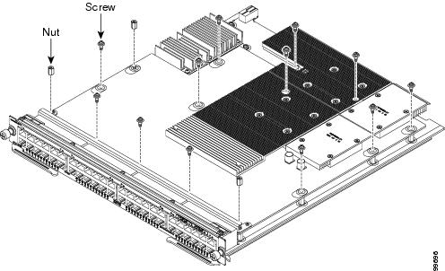
Figure 3 Removing the Mounting Screws (WS-F6K-VPWR)
Step 2
Grasp the inline-power daughter card at the edges and carefully lift up to disconnect the inline-power daughter card from the Ethernet module connectors.
Step 3
Carefully remove the inline-power daughter card from the module (see Figure 4) and set the inline-power daughter card on an antistatic mat or antistatic foam.
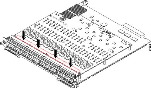
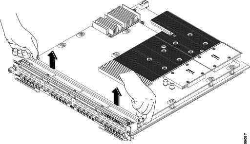
Figure 4 Removing the Inline-Power Daughter Card (WS-F6K-VPWR)
Step 4
If you are installing a replacement WS-F6K-VPWR inline-power daughter card, go to the "Installing the WS-F6K-VPWR Inline-Power Daughter Card" section. If you are installing the Ethernet module into the chassis, go to the "Installing the Ethernet Switching Module" section.
Installing the WS-F6K-VPWR Inline-Power Daughter Card
To install the WS-F6K-VPWR inline-power daughter card on the Ethernet baseboard, perform these steps:
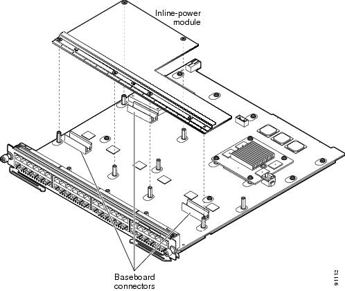
Step 1
Remove the inline-power daughter card from its protective packaging.
Step 2
Position the inline-power daughter card over the module standoffs as shown in Figure 5.
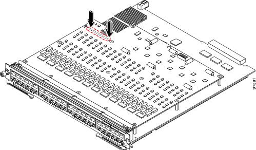
Figure 5 Positioning the Inline-Power Daughter Card over the Module (WS-F6K-VPWR)
Step 3
Carefully press down on the edges of the inline-power daughter card to seat the daughter card connectors to the module connectors.
Note
Make sure that you firmly seat the inline-power daughter card connectors to the module connectors.
Step 4
Install the six screws and carefully and evenly tighten the screws as shown in Figure 6.
CautionDo not overtighten the screws or you could damage the inline-power daughter card.
Figure 6 Installing the Mounting Screws (WS-F6K-VPWR)
Step 5
You are now ready to install the Ethernet module back into the chassis. Go to the "Installing the Ethernet Switching Module" section.
Removing and Installing the WS-F6K-VPWR-GE Inline-Power Daughter Card
The WS-F6K-VPWR-GE inline-power daughter card can be installed only on the following Ethernet modules:
•
WS-X6148-GE-TX
•
WS-X6548-GE-TX
The WS-F6K-VPWR inline-power daughter card supports Cisco prestandard inline power; it does not support IEEE 802.3af.
Removing the WS-F6K-VPWR-GE Inline-Power Daughter Card
To remove the WS-F6K-VPWR-GE inline-power daughter card on the Ethernet module, perform these steps:
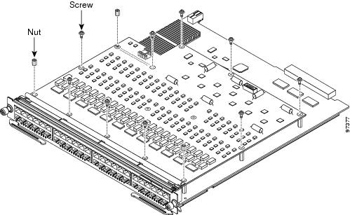
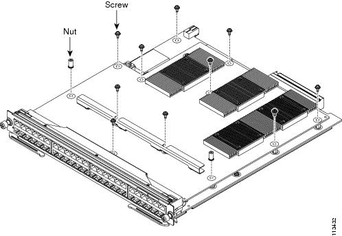
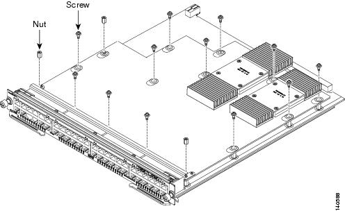
Step 1
Loosen and remove the nine screws and the three nuts securing the inline-power daughter card to the module. (See Figure 7.)
Figure 7 Removing the Inline-Power Daughter Card Mounting Screws and Nuts (WS-F6K-VPWR-GE)
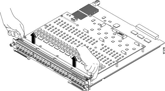
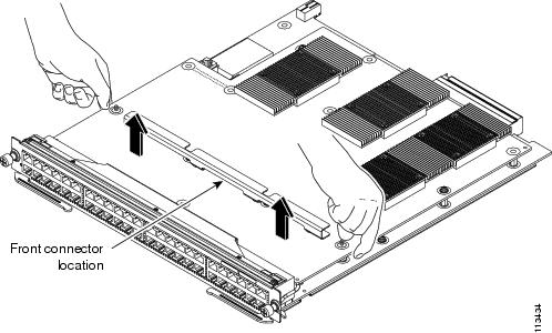
Step 2
Grasp the inline-power daughter card at the front edges and carefully lift up to disconnect the inline-power daughter card from the Ethernet module front connector. (See Figure 8.)
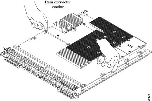
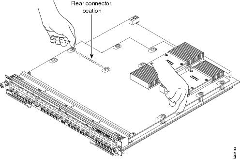
Figure 8 Disconnecting the Inline-Power Daughter Card Front Connector (WS-F6K-VPWR-GE)
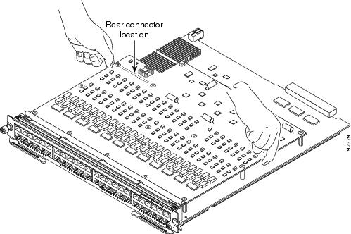
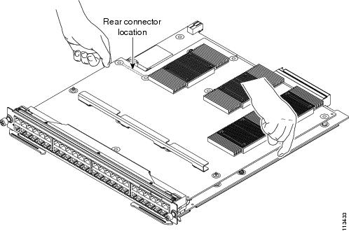
Step 3
Grasp the inline-power daughter card near the back edges, as shown in Figure 9, and carefully lift up to disconnect the inline-power daughter card connector from the Ethernet module rear connector.
Figure 9 Disconnecting the Inline-Power Daughter Card Rear Connector (WS-F6K-VPWR-GE)
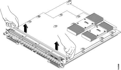
Step 4
Carefully remove the inline-power daughter card from the Ethernet module and set it on an antistatic mat or antistatic foam.
Step 5
If you are installing a replacement WS-F6K-VPWR-GE inline-power daughter card, go to the "Installing the WS-F6K-VPWR-GE Inline-Power Daughter Card" section. If you are installing the Ethernet module back into the chassis, go to the "Installing the Ethernet Switching Module" section.
Installing the WS-F6K-VPWR-GE Inline-Power Daughter Card
To install the WS-F6K-VPWR-GE inline-power daughter card on the module, perform these steps:
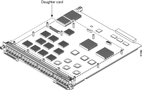
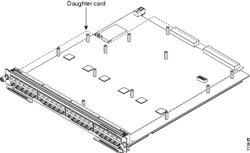
Step 1
Position the inline-power daughter card over the module and carefully align the three threaded studs on the module with the corresponding holes in the inline-power daughter card. (See Figure 10.). This step aligns the inline-power daughter card front and rear connectors with the module front and rear connectors.
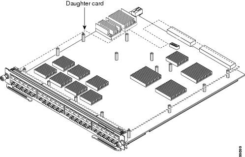
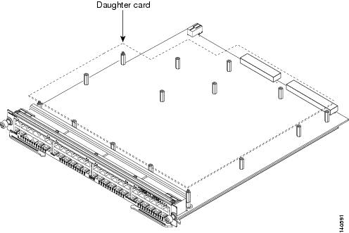
Figure 10 Positioning the Inline-Power Daughter Card Over the Module (WS-F6K-VPWR-GE)
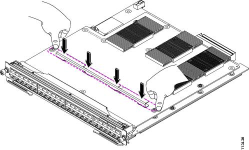
Step 2
Place your fingers on either side of the inline-power daughter card rear connector and press down to seat the inline-power daughter card on the Ethernet module rear connector. (See Figure 11.)
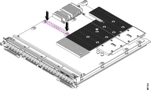
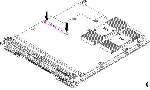
Figure 11 Seating the Inline-Power Daughter Card Rear Connector (WS-F6K-VPWR-GE)
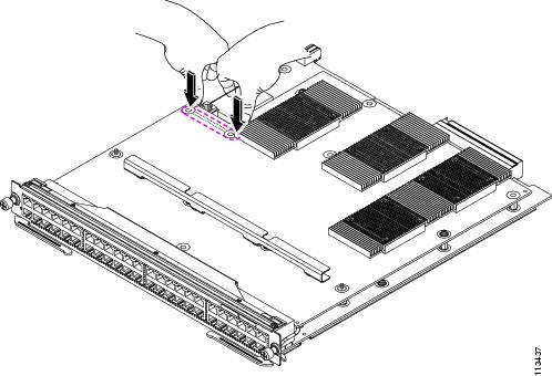
Step 3
Position your fingers along the stiffener on the front edge of the inline-power daughter card and press down firmly to seat the inline-power daughter card on the Ethernet module front connector. (See Figure 12.)
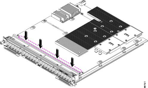
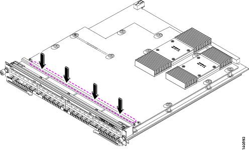
Figure 12 Seating the Inline-Power Daughter Card Front Connector (WS-F6K-VPWR-GE)
Step 4
Attach the inline-power daughter card to the Ethernet module with the nine screws and the three nuts. (See Figure 13.)
CautionDo not overtighten the screws and the nuts because you might damage the inline-power daughter card.
Figure 13 Attaching the Inline-Power Daughter Card to the Module (WS-F6K-VPWR-GE)
Step 5
You are now ready to install the Ethernet module back into the chassis. Go to the "Installing the Ethernet Switching Module" section.
Removing and Installing the WS-F6K-GE48-AF Inline-Power Daughter Card
The WS-F6K-GE48-AF inline-power daughter card can be installed only on the following Ethernet modules:
•
WS-X6148-GE-TX
•
WS-X6548-GE-TX
Note
The WS-F6K-GE48-AF inline-power daughter card supports both IEEE 802.3af and the Cisco prestandard.
Removing the WS-F6K-GE48-AF Inline-Power Daughter Card
To remove the WS-F6K-GE48-AF inline-power daughter card on the Ethernet module, perform these steps:
Step 1
Loosen and remove the 12 screws and the 3 nuts securing the inline-power daughter card to the Ethernet module. (See Figure 14.)
Tip
Three screws that secure the daughter card to the module pass through openings in the daughter card heat sinks. We recommend that you use a No. 1 Phillips screwdriver equipped with a magnetic tip to remove the three screws.
Figure 14 Removing the Inline-Power Daughter Card Mounting Screws and Nuts (WS-F6K-GE48-AF)
Step 2
Grasp the inline-power daughter card at the front edges and carefully lift up to disconnect the inline-power daughter card from the Ethernet module front connector. (See Figure 15.)
Figure 15 Disconnecting the Inline-Power Daughter Card Front Connector (WS-F6K-GE48-AF)
Step 3
Grasp the inline-power daughter card near the back edges, as shown in Figure 16, and carefully lift up to disconnect the inline-power daughter card connector from the Ethernet module rear connector.
Figure 16 Disconnecting the Inline-Power Daughter Card Rear Connector (WS-F6K-GE48-AF)
Step 4
Carefully remove the inline-power daughter card from the Ethernet module and set it on an antistatic mat or antistatic foam.
Step 5
If you are installing a replacement WS-F6K-GE48-AF inline-power daughter card, go to the "Installing the WS-F6K-GE48-AF Inline-Power Daughter Card" section. If you are installing the Ethernet module back into the chassis, go to the "Installing the Ethernet Switching Module" section.
Installing the WS-F6K-GE48-AF Inline-Power Daughter Card
To install the WS-F6K-GE48-AF inline-power daughter card on the Ethernet module, perform these steps:
Step 1
Position the inline-power daughter card over the module and carefully align the three threaded studs on the module with the corresponding holes in the inline-power daughter card. (See Figure 17.) This step aligns the inline-power daughter card connectors with the module connectors.
Figure 17 Positioning the Inline-Power Daughter Card Over the Module (WS-F6K-GE48-AF)
Step 2
Place your fingers on either side of the inline-power daughter card rear connector near the standoffs and press down to seat the inline-power daughter card on the module rear connector. (See Figure 18.)
Figure 18 Seating the Inline-Power Daughter Card Rear Connector (WS-F6K-GE48-AF)
Step 3
Position your fingers along the stiffener on the front edge of the inline-power daughter card and press down firmly to seat the inline-power daughter card on the module front connector. (See Figure 19.)
Figure 19 Seating the Inline-Power Daughter Card Front Connector (WS-F6K-GE48-AF)
Step 4
Attach the inline-power daughter card to the module with the twelve screws and the three nuts. (See Figure 20.)
Tip
Three screws that secure the daughter card to the module pass through openings in the daughter card heat sinks. We recommend that you use a No. 1 Phillips screwdriver equipped with a magnetic tip to install the three screws.
CautionDo not overtighten the screws and the nuts because you might damage the inline-power daughter card.
Figure 20 Securing the Inline-Power Daughter Card to the Module (WS-F6K-GE48-AF)
Step 5
You are now ready to install the Ethernet module back into the chassis. Go to the "Installing the Ethernet Switching Module" section.
Removing and Installing the WS-F6K-FE48X2-AF Inline-Power Daughter Card
The WS-F6K-FE48X2-AF inline-power daughter card is supported only on the WS-X6148X2-RJ-45 Ethernet module.
Note
The WS-F6K-FE48X2-AF inline-power daughter card supports both IEEE 802.3af and the Cisco prestandard.
Removing the WS-F6K-FE48X2-AF Inline-Power Daughter Card
To remove the WS-F6K-FE48X2-AF inline-power daughter card on the module, perform these steps:
Step 1
Loosen and remove the 10 screws and the 2 nuts securing the inline-power daughter card to the module. (See Figure 21.)
Figure 21 Removing the Inline-Power Daughter Card Mounting Screws (WS-F6K-FE48X2-AF)
Step 2
Grasp the inline-power daughter card at the rear edge and carefully lift up to disconnect the inline-power daughter card from the module rear connector. (See Figure 22.)
Figure 22 Disconnecting the Inline-Power Daughter Card Rear Connector (WS-F6K-FE48X2-AF)
Step 3
Grasp the inline-power daughter card near the front edges, as shown in Figure 23, and carefully lift up to disconnect the inline-power daughter card connector from the module front connector.
Figure 23 Disconnecting the Inline-Power Daughter Card Front Connector (WS-F6K-FE48X2-AF)
Step 4
Carefully remove the inline-power daughter card from the module and set it on an antistatic mat or antistatic foam.
Step 5
If you are installing a replacement WS-F6K-FE48X2-AF inline-power daughter card, go to the "Installing the WS-F6K-FE48X2-AF Inline-Power Daughter Card" section. If you are installing the Ethernet module back into the chassis, go to the "Installing the Ethernet Switching Module" section.
Installing the WS-F6K-FE48X2-AF Inline-Power Daughter Card
To install the WS-F6K-FE48X2-AF inline-power daughter card on the module, perform these steps:
Step 1
Position the inline-power daughter card over the module and carefully align the two threaded studs on the module with the corresponding holes in the inline-power daughter card. (See Figure 24.) This step aligns the inline-power daughter card connectors with the module connectors.
Figure 24 Positioning the Inline-Power Daughter Card Over the Module (WS-F6K-FE48X2-AF)
Step 2
Place your fingers on the stiffener bar and press down to seat the inline-power daughter card front connector on the module. (See Figure 25.)
Figure 25 Seating the Inline-Power Daughter Card Front Connector (WS-F6K-FE48X2-AF)
Step 3
Position your fingers over the inline-power daughter card rear connector and press down firmly to seat the inline-power daughter card on the module rear connector. (See Figure 26.)
Figure 26 Seating the Inline-Power Daughter Card Rear Connector (WS-F6K-FE48X2-AF)
Step 4
Attach the inline-power daughter card to the module with the 10 screws and the 2 nuts. (See Figure 27.)
CautionDo not overtighten the screws and the nuts because you might damage the inline-power daughter card.
Figure 27 Securing the Inline-Power Daughter Card to the Module (WS-F6K-FE48X2-AF)
Step 5
You are now ready to install the Ethernet module back into the chassis. Go to the "Installing the Ethernet Switching Module" section.
Removing and Installing the WS-F6K-48-AF Inline-Power Daughter Card
The WS-F6K-48-AF inline-power daughter card can be installed only on the following Ethernet modules:
•
WS-X6148-GE-TX
•
WS-X6148A-GE-TX
•
WS-X6148A-RJ-45
•
WS-X6548-GE-TX
Note
The WS-F6K-48-AF inline-power daughter card supports both IEEE 802.3af and the Cisco prestandard.
Removing the WS-F6K-48-AF Inline-Power Daughter Card
To remove the WS-F6K-48-AF inline-power daughter card on the Ethernet module, perform these steps:
Step 1
Loosen and remove the 12 screws and the 3 nuts securing the inline-power daughter card to the module. (See Figure 28.)
Figure 28 Removing the Inline-Power Daughter Card Mounting Screws and Nuts (WS-F6K-48-AF)
Step 2
Grasp the inline-power daughter card at the front edges and carefully lift up to disconnect the inline-power daughter card from the Ethernet module front connector. (See Figure 29.)
Figure 29 Disconnecting the Inline-Power Daughter Card Front Connector (WS-F6K-48-AF)
Step 3
Grasp the inline-power daughter card near the back edges, as shown in Figure 30, and carefully lift up to disconnect the inline-power daughter card connector from the Ethernet module rear connector.
Figure 30 Disconnecting the Inline-Power Daughter Card Rear Connector (WS-F6K-48-AF)
Step 4
Carefully remove the inline-power daughter card from the Ethernet module and set it on an antistatic mat or antistatic foam.
Step 5
If you are installing a replacement WS-F6K-48-AF inline-power daughter card, go to the "Installing the WS-F6K-48-AF Inline-Power Daughter Card" section. If you are installing the Ethernet module back into the chassis, go to the "Installing the Ethernet Switching Module" section.
Installing the WS-F6K-48-AF Inline-Power Daughter Card
To install the WS-F6K-48-AF inline-power daughter card on the Ethernet module, perform these steps:
Step 1
Position the inline-power daughter card over the module and carefully align the three threaded studs on the module with the corresponding holes in the inline-power daughter card. (See Figure 31.) This step aligns the inline-power daughter card connectors with the module connectors.
Figure 31 Positioning the Inline-Power Daughter Card Over the Module (WS-F6K-48-AF)
Step 2
Place your fingers on either side of the inline-power daughter card rear connector near the standoffs and press down to seat the inline-power daughter card on the module rear connector. (See Figure 32.)
Figure 32 Seating the Inline-Power Daughter Card Rear Connector (WS-F6K-48-AF)
Step 3
Position your fingers along the stiffener on the front edge of the inline-power daughter card and press down firmly to seat the inline-power daughter card on the Ethernet module front connector. (See Figure 33.)
Figure 33 Seating the Inline-Power Daughter Card Front Connector (WS-F6K-48-AF)
Step 4
Attach the inline-power daughter card to the module with the 12 screws and the 3 nuts. (See Figure 34.)
CautionDo not overtighten the screws and the nuts because you might damage the inline-power daughter card.
Figure 34 Securing the Inline-Power Daughter Card to the Module (WS-F6K-48-AF)
Step 5
You are now ready to install the Ethernet module back into the chassis. Go to the "Installing the Ethernet Switching Module" section.
Installing the Ethernet Switching Module
CautionTo prevent ESD damage, handle the modules by the carrier edges only.
CautionDuring this procedure, wear grounding wrist straps to avoid ESD damage to the card.
To reinstall the Ethernet switching module in the chassis, follow these steps:
Step 1
Verify that the captive installation screws are tightened on all modules installed in the switch chassis.
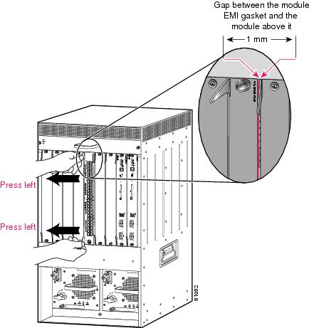
This action ensures that the EMI gaskets on all modules are fully compressed in order to maximize the opening space for the removed module.
Note
If the captive installation screws are loose, the EMI gaskets on the installed modules will push the adjacent modules toward the open slot, reducing the opening size and making it difficult to install the removed module.
Step 2
Fully open both ejector levers on the module being installed. (See Figure 35.)
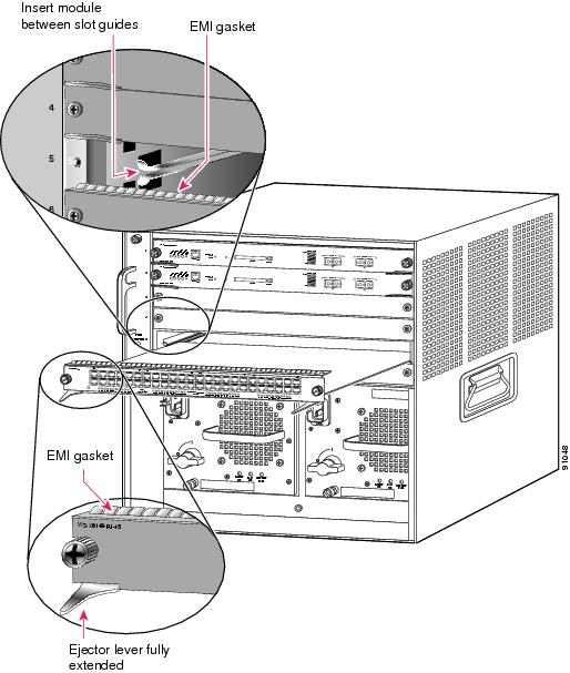
Figure 35 Positioning the Module in a Horizontal Slot Chassis
Step 3
Depending on the orientation of the slots in the chassis (horizontal or vertical), perform one of the following two sets of steps:
Horizontal slots
a.
Position the module in the slot. (See Figure 35.) Make sure that you align the sides of the module carrier with the slot guides on each side of the slot.
b.
Carefully slide the module into the slot until the EMI gasket along the top edge of the module makes contact with the module in the slot above it and both ejector levers have closed to approximately 45 degrees with respect to the module faceplate. (See Figure 36.)
c.
Using the thumb and forefinger of each hand, grasp the two ejector levers and press down to create a small 0.040 inch (1 mm) gap between the module's EMI gasket and the module above it. (See Figure 36.)
CautionDo not press down too forcefully on the levers because they will bend and get damaged.
d.
While pressing down, simultaneously close the left and right ejector levers to fully seat the module in the backplane connector. The ejector levers are fully closed when they are flush with the module faceplate. (See Figure 37.)
Note
Failure to fully seat the module in the backplane connector can result in error messages.
e.
Tighten the two captive installation screws on the module.
Note
Make sure that the ejector levers are fully closed before tightening the captive installation screws.
f.
Verify that the module STATUS LED is lit. Periodically check the STATUS LED. If the STATUS LED changes from orange to green, the module has successfully completed the boot process and is now online. If the STATUS LED remains orange or turns red, the module has not successfully completed the boot process and may have encountered an error.
Figure 36 Clearing the EMI Gasket in a Horizontal Slot Chassis
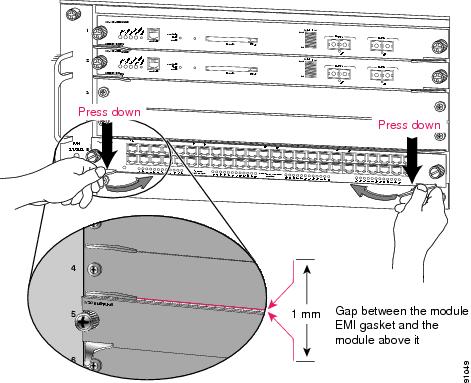
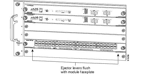
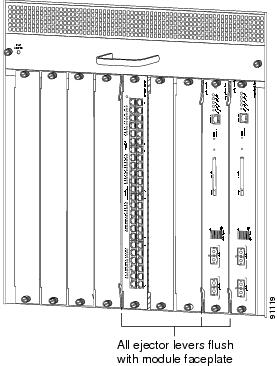
Figure 37 Closing the Ejector Levers in a Horizontal Slot Chassis
Vertical slots
a.
Position the module in the slot. (See Figure 38.) Make sure that you align the sides of the module carrier with the slot guides on the top and bottom of the slot.
b.
Carefully slide the module into the slot until the EMI gasket along the right edge of the module makes contact with the module in the slot adjacent to it and both ejector levers have closed to approximately 45 degrees with respect to the module faceplate. (See Figure 39.)
Figure 38 Positioning the Module in a Vertical Slot Chassis
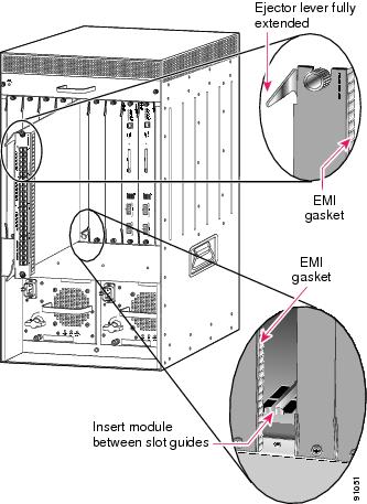
Figure 39 Clearing the EMI Gasket in a Vertical Slot Chassis
c.
Using the thumb and forefinger of each hand, grasp the two ejector levers and exert a slight pressure to the left, deflecting it approximately 0.040 inches (1 mm) creating a small gap between the module's EMI gasket and the module adjacent to it. (See Figure 39.)
CautionDo not exert too much pressure on the ejector levers because they will bend and get damaged.
d.
While pressing down on the ejector levers, simultaneously close the levers to fully seat the module in the backplane connector. The ejector levers are fully closed when they are flush with the module faceplate. (See Figure 40.)
e.
Tighten the two captive installation screws on the module.
Note
Make sure that the ejector levers are fully closed before tightening the captive installation screws.
f.
Verify that the module STATUS LED is lit. Periodically check the STATUS LED. If the STATUS LED changes from orange to green, the module has successfully completed the boot process and is now online. If the STATUS LED remains orange or turns red, the module has not successfully completed the boot process and may have encountered an error.
Figure 40 Closing the Ejector Levers in a Vertical Slot Chassis
Configuring the Module
Refer to the Catalyst 6500 Series Switch Software Configuration Guide or Catalyst 6500 Series Switch Cisco IOS Software Configuration Guide for information on configuring a Voice-over-IP (VoIP) network.
Regulatory Standards Compliance
When installed in a system, the Catalyst 6500 series switch modules comply with the standards listed in Table 5.
Table 5 Catalyst 6500 Series Switch Regulatory Compliance Specifications
Agency Approvals SpecificationCompliance
CE1 Marking
Safety
UL2 60950, CSA3 -C22.2 No. 60950, EN4 60950, IEC5 60950, AS/NZS 60950
EMC6
FCC7 Part 15 (CFR8 47) Class A, ICES9 -003 Class A, EN55022 Class A, CISPR22 Class A, AS/NZS 3548 Class A, and VCCI Class A, EN 55024, EN 50082-1, EN 61000-6-1, EN 300386, EN 61000-3-2, EN 61000-3-3
1 CE = European Compliance.
2 UL = Underwriters Laboratory.
3 CSA = Canadian Standards Association.
4 EN = European Norm.
5 IEC = International Electrotechnical Commission.
6 EMC = electromagnetic compatibility.
7 FCC = Federal Communications Commission.
8 CFR = Code of Federal Regulations.
9 ICES = Interference-Causing Equipment Standard.
Translated Safety Warnings
This section repeats in multiple languages the basic warnings that appear in this publication.
Statement 1001—Work During Lightning Activity
Statement 1021—SELV Circuit
Statement 1030—Equipment Installation
Statement 1034—Backplane Voltage
Statement 1041—Disconnecting Telephone-Network Cables
Statement 1072—Shock Hazard from Interconnections
Obtaining Documentation
Cisco documentation and additional literature are available on Cisco.com. Cisco also provides several ways to obtain technical assistance and other technical resources. These sections explain how to obtain technical information from Cisco Systems.
Cisco.com
You can access the most current Cisco documentation at this URL:
http://www.cisco.com/univercd/home/home.htm
You can access the Cisco website at this URL:
You can access international Cisco websites at this URL:
http://www.cisco.com/public/countries_languages.shtml
Documentation DVD
Cisco documentation and additional literature are available in a Documentation DVD package, which may have shipped with your product. The Documentation DVD is updated regularly and may be more current than printed documentation. The Documentation DVD package is available as a single unit.
Registered Cisco.com users (Cisco direct customers) can order a Cisco Documentation DVD (product number DOC-DOCDVD=) from the Ordering tool or Cisco Marketplace.
Cisco Ordering tool:
http://www.cisco.com/en/US/partner/ordering/
Cisco Marketplace:
http://www.cisco.com/go/marketplace/
Ordering Documentation
You can find instructions for ordering documentation at this URL:
http://www.cisco.com/univercd/cc/td/doc/es_inpck/pdi.htm
You can order Cisco documentation in these ways:
•
Registered Cisco.com users (Cisco direct customers) can order Cisco product documentation from the Ordering tool:
http://www.cisco.com/en/US/partner/ordering/
•
Nonregistered Cisco.com users can order documentation through a local account representative by calling Cisco Systems Corporate Headquarters (California, USA) at 408 526-7208 or, elsewhere in North America, by calling 1 800 553-NETS (6387).
Documentation Feedback
You can send comments about technical documentation to bug-doc@cisco.com.
You can submit comments by using the response card (if present) behind the front cover of your document or by writing to the following address:
Cisco Systems
Attn: Customer Document Ordering
170 West Tasman Drive
San Jose, CA 95134-9883We appreciate your comments.
Cisco Product Security Overview
Cisco provides a free online Security Vulnerability Policy portal at this URL:
http://www.cisco.com/en/US/products/products_security_vulnerability_policy.html
From this site, you can perform these tasks:
•
Report security vulnerabilities in Cisco products.
•
Obtain assistance with security incidents that involve Cisco products.
•
Register to receive security information from Cisco.
A current list of security advisories and notices for Cisco products is available at this URL:
If you prefer to see advisories and notices as they are updated in real time, you can access a Product Security Incident Response Team Really Simple Syndication (PSIRT RSS) feed from this URL:
http://www.cisco.com/en/US/products/products_psirt_rss_feed.html
Reporting Security Problems in Cisco Products
Cisco is committed to delivering secure products. We test our products internally before we release them, and we strive to correct all vulnerabilities quickly. If you think that you might have identified a vulnerability in a Cisco product, contact PSIRT:
•
Emergencies — security-alert@cisco.com
•
Nonemergencies — psirt@cisco.com
Tip
We encourage you to use Pretty Good Privacy (PGP) or a compatible product to encrypt any sensitive information that you send to Cisco. PSIRT can work from encrypted information that is compatible with PGP versions 2.x through 8.x.
Never use a revoked or an expired encryption key. The correct public key to use in your correspondence with PSIRT is the one that has the most recent creation date in this public key server list:
http://pgp.mit.edu:11371/pks/lookup?search=psirt%40cisco.com&op=index&exact=on
In an emergency, you can also reach PSIRT by telephone:
•
1 877 228-7302
•
1 408 525-6532
Obtaining Technical Assistance
For all customers, partners, resellers, and distributors who hold valid Cisco service contracts, Cisco Technical Support provides 24-hour-a-day, award-winning technical assistance. The Cisco Technical Support Website on Cisco.com features extensive online support resources. In addition, Cisco Technical Assistance Center (TAC) engineers provide telephone support. If you do not hold a valid Cisco service contract, contact your reseller.
Cisco Technical Support Website
The Cisco Technical Support Website provides online documents and tools for troubleshooting and resolving technical issues with Cisco products and technologies. The website is available 24 hours a day, 365 days a year, at this URL:
http://www.cisco.com/techsupport
Access to all tools on the Cisco Technical Support Website requires a Cisco.com user ID and password. If you have a valid service contract but do not have a user ID or password, you can register at this URL:
http://tools.cisco.com/RPF/register/register.do
Note
Use the Cisco Product Identification (CPI) tool to locate your product serial number before submitting a web or phone request for service. You can access the CPI tool from the Cisco Technical Support Website by clicking the Tools & Resources link under Documentation & Tools. Choose Cisco Product Identification Tool from the Alphabetical Index drop-down list, or click the Cisco Product Identification Tool link under Alerts & RMAs. The CPI tool offers three search options: by product ID or model name; by tree view; or for certain products, by copying and pasting show command output. Search results show an illustration of your product with the serial number label location highlighted. Locate the serial number label on your product and record the information before placing a service call.
Submitting a Service Request
Using the online TAC Service Request Tool is the fastest way to open S3 and S4 service requests. (S3 and S4 service requests are those in which your network is minimally impaired or for which you require product information.) After you describe your situation, the TAC Service Request Tool provides recommended solutions. If your issue is not resolved using the recommended resources, your service request is assigned to a Cisco TAC engineer. The TAC Service Request Tool is located at this URL:
http://www.cisco.com/techsupport/servicerequest
For S1 or S2 service requests or if you do not have Internet access, contact the Cisco TAC by telephone. (S1 or S2 service requests are those in which your production network is down or severely degraded.) Cisco TAC engineers are assigned immediately to S1 and S2 service requests to help keep your business operations running smoothly.
To open a service request by telephone, use one of the following numbers:
Asia-Pacific: +61 2 8446 7411 (Australia: 1 800 805 227)
EMEA: +32 2 704 55 55
USA: 1 800 553-2447For a complete list of Cisco TAC contacts, go to this URL:
http://www.cisco.com/techsupport/contacts
Definitions of Service Request Severity
To ensure that all service requests are reported in a standard format, Cisco has established severity definitions.
Severity 1 (S1)—Your network is "down," or there is a critical impact to your business operations. You and Cisco will commit all necessary resources around the clock to resolve the situation.
Severity 2 (S2)—Operation of an existing network is severely degraded, or significant aspects of your business operation are negatively affected by inadequate performance of Cisco products. You and Cisco will commit full-time resources during normal business hours to resolve the situation.
Severity 3 (S3)—Operational performance of your network is impaired, but most business operations remain functional. You and Cisco will commit resources during normal business hours to restore service to satisfactory levels.
Severity 4 (S4)—You require information or assistance with Cisco product capabilities, installation, or configuration. There is little or no effect on your business operations.
Obtaining Additional Publications and Information
Information about Cisco products, technologies, and network solutions is available from various online and printed sources.
•
Cisco Marketplace provides a variety of Cisco books, reference guides, and logo merchandise. Visit Cisco Marketplace, the company store, at this URL:
http://www.cisco.com/go/marketplace/
•
Cisco Press publishes a wide range of general networking, training and certification titles. Both new and experienced users will benefit from these publications. For current Cisco Press titles and other information, go to Cisco Press at this URL:
•
Packet magazine is the Cisco Systems technical user magazine for maximizing Internet and networking investments. Each quarter, Packet delivers coverage of the latest industry trends, technology breakthroughs, and Cisco products and solutions, as well as network deployment and troubleshooting tips, configuration examples, customer case studies, certification and training information, and links to scores of in-depth online resources. You can access Packet magazine at this URL:
•
iQ Magazine is the quarterly publication from Cisco Systems designed to help growing companies learn how they can use technology to increase revenue, streamline their business, and expand services. The publication identifies the challenges facing these companies and the technologies to help solve them, using real-world case studies and business strategies to help readers make sound technology investment decisions. You can access iQ Magazine at this URL:
http://www.cisco.com/go/iqmagazine
•
Internet Protocol Journal is a quarterly journal published by Cisco Systems for engineering professionals involved in designing, developing, and operating public and private internets and intranets. You can access the Internet Protocol Journal at this URL:
•
World-class networking training is available from Cisco. You can view current offerings at this URL:
http://www.cisco.com/en/US/learning/index.html
CCSP, CCVP, the Cisco Square Bridge logo, Follow Me Browsing, and StackWise are trademarks of Cisco Systems, Inc.; Changing the Way We Work, Live, Play, and Learn, and iQuick Study are service marks of Cisco Systems, Inc.; and Access Registrar, Aironet, ASIST, BPX, Catalyst, CCDA, CCDP, CCIE, CCIP, CCNA, CCNP, Cisco, the Cisco Certified Internetwork Expert logo, Cisco IOS, Cisco Press, Cisco Systems, Cisco Systems Capital, the Cisco Systems logo, Cisco Unity, Empowering the Internet Generation, Enterprise/Solver, EtherChannel, EtherFast, EtherSwitch, Fast Step, FormShare, GigaDrive, GigaStack, HomeLink, Internet Quotient, IOS, IP/TV, iQ Expertise, the iQ logo, iQ Net Readiness Scorecard, LightStream, Linksys, MeetingPlace, MGX, the Networkers logo, Networking Academy, Network Registrar, Packet, PIX, Post-Routing, Pre-Routing, ProConnect, RateMUX, ScriptShare, SlideCast, SMARTnet, StrataView Plus, TeleRouter, The Fastest Way to Increase Your Internet Quotient, and TransPath are registered trademarks of Cisco Systems, Inc. and/or its affiliates in the United States and certain other countries.
All other trademarks mentioned in this document or Website are the property of their respective owners. The use of the word partner does not imply a partnership relationship between Cisco and any other company. (0502R)
© 2000-2005 Cisco Systems, Inc. All rights reserved.


