Table Of Contents
Catalyst 6000 Family Multilayer Switch Feature Card 2 Installation Note
Preparing the Supervisor Engine
Removing the MSFC from the Supervisor Engine 1A
Obtaining Technical Assistance
Catalyst 6000 Family Multilayer Switch Feature Card 2 Installation Note
Product number: WS-F6K-MSFC2=
This publication describes how to install the Catalyst 6000 Family Multilayer Switch Feature Card 2 (MSFC2) on a Supervisor Engine 1A or Supervisor Engine 2.
Contents
This publication contains these sections:
•
Preparing the Supervisor Engine
•
Removing the MSFC from the Supervisor Engine 1A
•
Obtaining Technical Assistance
Safety Overview
Safety warnings appear throughout this publication in procedures that may harm you if performed incorrectly. A warning symbol precedes each warning statement.
Warning
Only trained and qualified personnel should be allowed to install or replace this equipment.
Features
The MSFC2 ships with 128-MB SDRAM at 100 MHz with Error Checking and Correction (ECC) (single-bit error detection and correction; 2-bit error detection) as the default and is upgradeable to 256 MB or 512 MB.
Table 1 lists the Cisco IOS features available for the MSFC2.
Table 1 Cisco IOS Features
Layer 3 Forwarding FeaturesWire-speed IP, IP multicast, and IPX routing between VLANs (switches running the Cisco IOS for the Catalyst 6000 Family of Switches product can also route between ports)
Support for up to 128,000 entries for IP network prefixes, IP unicast and multicast addresses, IPX network numbers, and MAC addresses1
FIB2 and adjacency database support as defined in other Cisco routers
Destination-based load sharing among equal cost paths
Layer 3 Routing ProtocolsStatic IP routing
IP routing protocols: IGRP3 , EIGRP4 , OSPF5 , RIP6 , and RIP-2
IP multicast routing protocols: PIM7 (sparse and dense mode) and DVMRP8 interrupt
IPX routing protocols: RIP, NLSP9 , and EIGRP
Layer 3 Related ProtocolsIGMP10 v1 and v2
IGMP snooping
CGMP11 server support
Full ICMP12 support
GDP13
IRDP14
MSDP15
MBGP16
Enhanced ServicesStandard DNS17 support
MHSRP20
CDP21
Wire-speed IP standard ACL support
Standard reflexive ACL
Layer 3 QoS22 Related FeaturesTwo priority queues for CoS23 -based operation
IP precedence-based IP forwarding
1 An MLS cache larger than 32,000 entries increases the probability that a flow will not be switched by the PFC and will get forwarded to the router
2 FIB = forwarding information base
3 IGRP = Interior Gateway Routing Protocol
4 EIGRP = Enhanced Interior Gateway Routing Protocol
5 OSPF = Open Shortest Path First
6 RIP = Routing Information Protocol
7 PIM = Protocol Independent Multicast
8 DVMRP = Distance Vector Multicast Routing Protocol
9 NLSP = NetWare Link Services Protocol
10 IGMP = Internet Group Management Protocol
11 CGMP = Cisco Group Multicast Protocol
12 ICMP = Internet Control Message Protocol
13 GDP = Gateway Discovery Protocol
14 IRDP = ICMP Router Discovery Protocol
15 MSDP = Multicast Source Discovery Protocol
16 MBGP = Multicast Border Gateway Protocol
17 DNS = Domain Naming System
18 DHCP = Dynamic Host Configuration Protocol
19 BOOTP = Boot Protocol
20 MHSRP = Multigroup Hot Standby Routing Protocol
21 CDP = Cisco Discovery Protocol
22 QoS = Quality of Service
23 CoS = Class of Service
Software Requirements
The software requirements are as follows:
•
For switches with Cisco IOS on the Catalyst 6000 Family of Switches product on both the supervisor engine and the MSFC2:
Cisco IOS Release 12.1(2)E or later on both the supervisor engine and the MSFC2. The image required to support this is c6sup12-*-mz, where * is one of the various versions (such as js, is, ds). When you upgrade from MSFC to MSFC2, you need to upgrade the c6sup-*-mz or c6sup11-*-mz image to the new c6sup12-*-mz image.
•
For switches with Catalyst supervisor engine software on the supervisor engine and Cisco IOS software on the MSFC2:
–
Catalyst 6000 family supervisor engine software release 5.4(3) or later
–
Cisco IOS Release 12.1(2)E or later on the MSFC2
Parts List
These parts are in the replacement kit:
•
One Catalyst 6000 MSFC2 (WS-F6K-MSFC2=)
•
One disposable grounding wrist strap
•
One bag of spare mounting screws
Required Tools
These tools are required to perform the installation of the MSFC2:
•
Antistatic mat or foam pad to support the removed supervisor engine
•
3/16-inch flat-blade screwdriver for the captive installation screws on the supervisor engine
•
Number 1 Phillips screwdriver for the screws and cap nut that fasten the MSFC2 to the supervisor engine
•
Your own ESD-prevention equipment or the disposable grounding wrist strap included with all upgrade kits, field-replaceable units (FRUs), and spares
Refer to the Site Preparation and Safety Guide for ESD details including the locations of the ESD connectors on the Catalyst 6000 family switches.
Installation Guidelines
Follow these guidelines when installing an MSFC2 on a supervisor engine:
•
The hardware on both supervisor engines in a single chassis must be identical. You cannot mix an MSFC and an MSFC2 in the same chassis. You must shut down the switch to install the MSFC2, even if you have redundant supervisor engines.
•
If you have redundant supervisor engines, you must install an MSFC2 on each supervisor engine.
•
The Supervisor Engine 1A with only a PFC cannot be upgraded to MSFC2. There are no standoffs installed for securing the MSFC2 to the supervisor engine.
•
The Supervisor Engine 1A with a PFC and an MSFC (WS-X6K-SUP1A-MSFC) can be upgraded to an MSFC2. You must remove the existing MSFC from the Supervisor Engine 1A. The MSFC2 uses the same standoffs used for the MSFC.
•
The Supervisor Engine 2 with a PFC2 (WS-X6K-SUP2-2GE) can be upgraded to an MSFC2. The supervisor engine has standoffs installed for securing the MSFC2 to the supervisor engine.
Preparing the Supervisor Engine
Note
Review the guidelines in the "Software Requirements" section before you prepare the supervisor engine.
To install the MSFC2 on a Supervisor Engine 1A with a PFC and an MSFC, you must shut down the switch, remove the Supervisor Engine 1A from the chassis, and remove the MSFC from the Supervisor Engine 1A.
To install the MSFC2 on a Supervisor Engine 2, you must shut down the switch and remove the Supervisor Engine 2 from the chassis.
CautionAlways use an ESD wrist strap when handling modules or coming into contact with internal components.
Before you remove a supervisor engine, you should first upload the current configuration to a server. This saves time when bringing the module back online. You can recover the configuration by downloading it from the server to the nonvolatile memory of the supervisor engine. For more information, refer to Chapter 26, "Working with Configuration Files," in the Catalyst 6000 Family Software Configuration Guide.
To prepare the supervisor engine, follow these steps:
Step 1
Upload the current configuration to a server. On any modules running Cisco IOS, save the running configuration.
Step 2
Shut down the switch.
Step 3
Remove the supervisor engine from the Catalyst 6000 family switch. (Refer to the Catalyst 6000 Family Module Installation Guide for removal instructions.)
Step 4
Place the supervisor engine on an antistatic mat or foam.
To remove the MSFC from the Supervisor Engine 1A, see the "Removing the MSFC from the Supervisor Engine 1A" section and follow the instructions for removing the MSFC.
To install the MSFC2 on a Supervisor Engine 2, see the "Installing the MSFC2" section and follow the instructions for installing the MSFC2.
Removing the MSFC from the Supervisor Engine 1A
Note
You must remove the Flash SIMM from the MSFC to access two mounting screws that are located under the SIMM.
CautionHandle the SIMM by its edges only; avoid touching the memory module, pins, or traces (the metal fingers along the connector edge of the SIMM). SIMMs are sensitive components that are susceptible to ESD damage and can be shorted by mishandling.
To remove the MSFC from the Supervisor Engine 1A, follow these steps:
Step 1
Note that the Flash SIMM is located at the rear of the MSFC (see Figure 1). Pull the locking spring clips on both sides of the Flash SIMM outward and tilt the Flash SIMM free of the clips (see Figure 2). Be careful not to break the clips on the Flash SIMM connector.
Figure 1 Flash SIMM Location on the MSFC
Figure 2 Removing the Flash SIMM
Step 2
Hold the SIMM by the edges and gently lift and remove it, placing it on an antistatic mat or foam.
Step 3
Remove the securing screws and cap nut (see Figure 3).
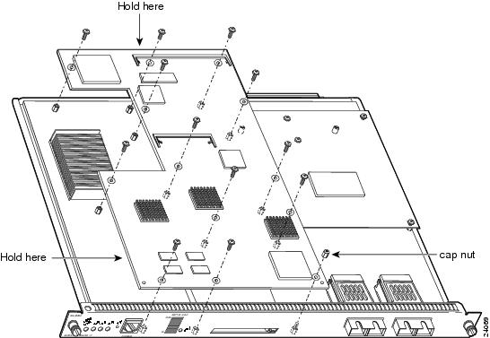
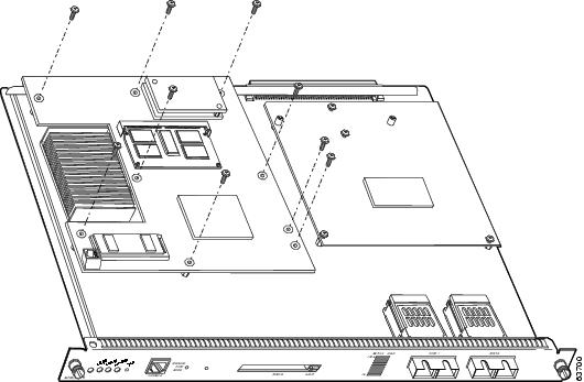
Figure 3 Removing Securing Screws and Cap Nut
Step 4
Hold the top edge of the MSFC with your right hand and the bottom-left edge with your left hand (see Figure 3). Gently lift the MSFC with both hands simultaneously and remove the MSFC from the supervisor engine.
CautionUse care not to damage the connectors on the supervisor engine. If you damage a connector, you will have to return the supervisor engine to Cisco for repair.
Step 5
Place the MSFC on an antistatic mat or antistatic foam pad.
Installing the MSFC2
Note
The MSFC2 is designed to be installed on a Supervisor Engine 1A and a Supervisor Engine 2. The standoff locations on the different supervisor engines may not be the same. Not all mounting holes on the MSFC2 will be used in all installations. Visually verify that there are standoffs beneath the mounting holes before installing the securing screws.
To install the MSFC2 on the supervisor engine, follow these steps:
Step 1
Remove the MSFC2 from its antistatic bag.
Step 2
Align the MSFC2 with the standoffs on the supervisor engine. (See Figure 4).
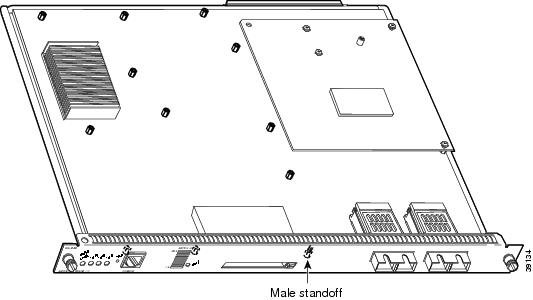
Figure 4 Male Standoff Location on the Supervisor Engine
Step 3
Ensure that the connectors on the MSFC2 (see Figure 5) are aligned with the connectors on the supervisor engine.
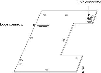
Figure 5 MSFC2 Connectors
Step 4
Carefully seat the MSFC2 onto the supervisor engine (see Figure 6).
Step 5
Using your thumbs, apply pressure at the locations shown in Figure 6 to ensure that the MSFC2 is securely seated on the supervisor engine.
CautionEnsure that the MSFC2 is securely seated before you install and tighten the cap nut and securing screws. Using the screws to seat the MSFC2 could warp the card.
CautionUse care not to damage the connectors on the supervisor engine. If you damage a connector, you will have to return the supervisor engine to Cisco for repair.
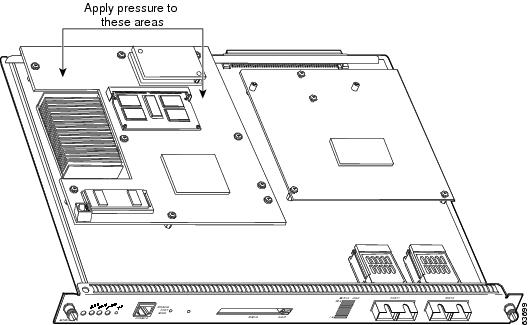
Figure 6 Seating the MSFC2 on the Supervisor Engine
Step 6
Use a Phillips-head screwdriver to install the screws that secure the MSFC2 to the supervisor engine. (See Figure 7).
CautionYou must install all screws. The screws provide grounding between the MSFC 2 and the supervisor engine. Failure to install all screws will invalidate the safety approvals and can cause fire and electrical hazards.
Figure 7 Installing the Screws
Step 7
Install the supervisor engine in the Catalyst 6000 family switch. (Refer to the Catalyst 6000 Family Module Installation Guide for installation instructions.)
CautionThe hardware on both supervisor engines in a single chassis must be identical. If you have redundant supervisor engines, you must install an MSFC2 on each supervisor engine.
Step 8
If you are installing an MSFC2 on a redundant supervisor engine, go to Step 3 in the "Preparing the Supervisor Engine" section and follow the procedure for removing the supervisor engine.
Step 9
Power up the switch.
Step 10
Depending on the software running on the switch, do one of the following steps to verify the installation:
•
Cisco IOS for the Catalyst 6000 Family of Switches product on the supervisor engine and the MSFC2:
Verify that the switch is online. This indicates that the system acknowledges the new module and has brought it online.
•
Catalyst supervisor engine software on the supervisor engine and Cisco IOS on the MSFC2:
Enter the show module command to verify that the system acknowledges the new module and has brought it online.
This example shows the output of the show module command:
Console> show moduleMod Slot Ports Module-Type Model Status--- ---- ----- ------------------------- ------------------- --------1 1 2 1000BaseX Supervisor WS-X6K-SUP1A-2GE ok15 1 1 Multilayer Switch Feature WS-F6K-MSFC2 ok2 1 2 1000BaseX Supervisor WS-X6K-SUP1A-2GE ok16 1 1 Multilayer Switch Feature WS-F6K-MSFC2 standby.<display text omitted>.Console>
Related Documentation
For additional information on Catalyst 6000 family switches and command-line interface (CLI) commands, refer to the following publications:
•
Regulatory Compliance and Safety Information for the Catalyst 6000 Family Switches
•
Catalyst 6000 Family Installation Guide
•
Catalyst 6000 Family Module Installation Guide
•
Catalyst 6000 Family Software Configuration Guide
•
Catalyst 6000 Family Command Reference
•
Catalyst 6000 Family IOS Software Configuration Guide
•
Catalyst 6000 Family IOS Command Reference
•
System Message Guide—Catalyst 6000 Family, Catalyst 5000 Family, Catalyst 4000 Family, Catalyst 2926G Series, Catalyst 2948G, and Catalyst 2980G Switches
•
Site Preparation and Safety Guide
Obtaining Documentation
The following sections provide sources for obtaining documentation from Cisco Systems.
World Wide Web
You can access the most current Cisco documentation on the World Wide Web at the following sites:
Documentation CD-ROM
Cisco documentation and additional literature are available in a CD-ROM package, which ships with your product. The Documentation CD-ROM is updated monthly and may be more current than printed documentation. The CD-ROM package is available as a single unit or as an annual subscription.
Ordering Documentation
Cisco documentation is available in the following ways:
•
Registered Cisco Direct Customers can order Cisco Product documentation from the Networking Products MarketPlace:
http://www.cisco.com/cgi-bin/order/order_root.pl
•
Registered Cisco.com users can order the Documentation CD-ROM through the online Subscription Store:
http://www.cisco.com/go/subscription
•
Nonregistered Cisco.com users can order documentation through a local account representative by calling Cisco corporate headquarters (California, USA) at 408 526-7208 or, in North America, by calling 800 553-NETS(6387).
Documentation Feedback
If you are reading Cisco product documentation on the World Wide Web, you can submit technical comments electronically. Click Feedback in the toolbar and select Documentation. After you complete the form, click Submit to send it to Cisco.
You can e-mail your comments to bug-doc@cisco.com.
To submit your comments by mail, use the response card behind the front cover of your document, or write to the following address:
Attn Document Resource Connection
Cisco Systems, Inc.
170 West Tasman Drive
San Jose, CA 95134-9883We appreciate your comments.
Obtaining Technical Assistance
Cisco provides Cisco.com as a starting point for all technical assistance. Customers and partners can obtain documentation, troubleshooting tips, and sample configurations from online tools. For Cisco.com registered users, additional troubleshooting tools are available from the TAC website.
Cisco.com
Cisco.com is the foundation of a suite of interactive, networked services that provides immediate, open access to Cisco information and resources at anytime, from anywhere in the world. This highly integrated Internet application is a powerful, easy-to-use tool for doing business with Cisco.
Cisco.com provides a broad range of features and services to help customers and partners streamline business processes and improve productivity. Through Cisco.com, you can find information about Cisco and our networking solutions, services, and programs. In addition, you can resolve technical issues with online technical support, download and test software packages, and order Cisco learning materials and merchandise. Valuable online skill assessment, training, and certification programs are also available.
Customers and partners can self-register on Cisco.com to obtain additional personalized information and services. Registered users can order products, check on the status of an order, access technical support, and view benefits specific to their relationships with Cisco.
To access Cisco.com, go to the following website:
Technical Assistance Center
The Cisco TAC is available to all customers who need technical assistance with a Cisco product, technology, or solution. Two types of support are available through the Cisco TAC: the Cisco TAC Web Site and the Cisco TAC Escalation Center.
Inquiries to Cisco TAC are categorized according to the urgency of the issue:
•
Priority level 4 (P4)—You need information or assistance concerning Cisco product capabilities, product installation, or basic product configuration.
•
Priority level 3 (P3)—Your network performance is degraded. Network functionality is noticeably impaired, but most business operations continue.
•
Priority level 2 (P2)—Your production network is severely degraded, affecting significant aspects of business operations. No workaround is available.
•
Priority level 1 (P1)—Your production network is down, and a critical impact to business operations will occur if service is not restored quickly. No workaround is available.
Which Cisco TAC resource you choose is based on the priority of the problem and the conditions of service contracts, when applicable.
Cisco TAC Web Site
The Cisco TAC Web Site allows you to resolve P3 and P4 issues yourself, saving both cost and time. The site provides around-the-clock access to online tools, knowledge bases, and software. To access the Cisco TAC Web Site, go to the following URL:
All customers, partners, and resellers who have a valid Cisco services contract have complete access to the technical support resources on the Cisco TAC Web Site. The Cisco TAC Web Site requires a Cisco.com login ID and password. If you have a valid service contract but do not have a login ID or password, go to the following URL to register:
http://www.cisco.com/register/
If you cannot resolve your technical issues by using the Cisco TAC Web Site, and you are a Cisco.com registered user, you can open a case online by using the TAC Case Open tool at the following URL:
http://www.cisco.com/tac/caseopen
If you have Internet access, it is recommended that you open P3 and P4 cases through the Cisco TAC Web Site.
Cisco TAC Escalation Center
The Cisco TAC Escalation Center addresses issues that are classified as priority level 1 or priority level 2; these classifications are assigned when severe network degradation significantly impacts business operations. When you contact the TAC Escalation Center with a P1 or P2 problem, a Cisco TAC engineer will automatically open a case.
To obtain a directory of toll-free Cisco TAC telephone numbers for your country, go to the following URL:
http://www.cisco.com/warp/public/687/Directory/DirTAC.shtml
Before calling, please check with your network operations center to determine the level of Cisco support services to which your company is entitled; for example, SMARTnet, SMARTnet Onsite, or Network Supported Accounts (NSA). In addition, please have available your service agreement number and your product serial number.
![]()


