Cisco Clock Module (WS-C6K-CL and WS-C6513-CL) and VTT Module (WS-C6K-VTT) Installation Note
Available Languages
Table Of Contents
Cisco Clock Module (WS-C6K-CL and WS-C6513-CL) and VTT Module (WS-C6K-VTT) Installation Note
Checking the VTT Module and Clock Module
Replacing the VTT Modules and Clock Modules
Removing the Front Panel Safety Cover
Locating the VTT Modules and Clock Modules
Obtaining Documentation and Submitting a Service Request
Cisco Clock Module (WS-C6K-CL and WS-C6513-CL) and VTT Module (WS-C6K-VTT) Installation Note
Product Numbers:
WS-C6K-VTT=
WS-C6K-CL=
WS-C6513-CL=This publication describes how to check the status of the voltage termination (VTT) modules and clock modules and describes how to remove and install the modules on the following Catalyst 6500 series switches and Cisco 7600 series routers:

Note
For information on replacing the clock module on the Catalyst 6503 and 6509-NEB-A switches, and the Cisco 7603, 7606, and 7609 (CISCO7609) routers, refer to the Cisco Clock Module CLK-7600 Installation Note at this URL:
http://www.cisco.com/univercd/cc/td/doc/product/core/cis7600/hardware/78_15002.htm
Contents
This publication consists of the following sections:
•
•
•
Parts List
The following parts are included in the replacement kit:
•
–
–
–
–
•
–
–
–
–
Required Tools
These tools are required to perform the installation:
•
•
Safety Overview
Safety warnings appear throughout this publication in procedures that may harm you if performed incorrectly. A warning symbol precedes each warning statement.

Warning
Checking the VTT Module and Clock Module
To check the status of your module, do one of the following:
•
This example shows how to check the status of the VTT modules and clock modules on a system running Catalyst software:
Console> show environmentEnvironmental Status (. = Pass, F = Fail, U = Unknown, N = Not Present)PS1:. PS2:N PS1 Fan:. PS2 Fan:NChassis-Ser-EEPROM:. Fan:.Clock(A/B):B Clock A:F Clock B:.VTT1:. VTT2:F VTT3:.Console>The above example shows a failure with clock module A and VTT module 2.
•
This example shows how to check the status of the VTT modules and clock modules on a system running Cisco IOS software:
Router> show environment statusbackplane:operating clock count:1operating VTT count:2...VTT 1:VTT 1 OK: OKVTT 2:VTT 2 OK: not OKVTT 3:VTT 3 OK: OKclock 1:clock 1 OK: not OK, clock 1 clock-inuse: not-in-useclock 2:clock 2 OK: OK, clock 2 clock-inuse: in-use...Router>The above example shows a failure with clock module A (clock 1) and VTT module 2.
Replacing the VTT Modules and Clock Modules
This section consists of these subsections:
•
•
Removing the Front Panel Safety Cover
To replace the VTT modules or clock module, you must first shut down the switch and remove the front (non-module) panel safety cover of the switch chassis.

Caution
To remove the front panel safety cover, perform these steps:
Step 1
Step 2
Warning
Step 3
•
•
•
•
•
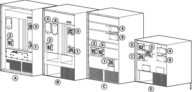
Locating the VTT Modules and Clock Modules
See Figure 1 for the location of the VTT modules and clock modules on the Catalyst 6500 series switches, and the Cisco 7609 (OSR-7609 and CISCO7609) and 7613 routers.
Note
http://www.cisco.com/univercd/cc/td/doc/product/core/cis7600/hardware/78_15002.htm
Note
Figure 1 VTT Module and Clock Module Location
Replacing the VTT Module
Note
If all VTT module manufacturing assembly numbers are 73-4354-02 Rev A0, replace only the failed module.
Caution
Note
To replace the VTT module, perform these steps:
Step 1
Step 2
Step 3
Step 4
Step 5
Step 6
Step 7
Step 8
Warning
Step 9
This example shows that the VTT module is functioning properly:
Console> show environmentEnvironmental Status (. = Pass, F = Fail, U = Unknown, N = Not Present)PS1:. PS2:N PS1 Fan:. PS2 Fan:NChassis-Ser-EEPROM:. Fan:.Clock(A/B):A Clock A:. Clock B:.VTT1:. VTT2:. VTT3:.Console>
Replacing the Clock Module
Caution
Note
To replace the clock module, perform these steps:
Step 1
Step 2
Step 3
Step 4
Step 5
Step 6
Step 7
Step 8
Warning
Step 9
This example shows that the clock module is functioning properly:
Console> show environmentEnvironmental Status (. = Pass, F = Fail, U = Unknown, N = Not Present)PS1:. PS2:N PS1 Fan:. PS2 Fan:NChassis-Ser-EEPROM:. Fan:.Clock(A/B):A Clock A:. Clock B:.VTT1:. VTT2:. VTT3:.Console>
Related Documentation
For additional information on Catalyst 6500 series switches and command-line interface (CLI) commands, refer to the following publications:
•
•
•
•
•
•
•
•
•
Obtaining Documentation and Submitting a Service Request
For information on obtaining documentation, submitting a service request, and gathering additional information, see the monthly What's New in Cisco Product Documentation, which also lists all new and revised Cisco technical documentation, at:
http://www.cisco.com/en/US/docs/general/whatsnew/whatsnew.html
Subscribe to the What's New in Cisco Product Documentation as a Really Simple Syndication (RSS) feed and set content to be delivered directly to your desktop using a reader application. The RSS feeds are a free service and Cisco currently supports RSS Version 2.0.
This document is to be used in conjunction with the documents listed in the "Related Documentation" section.

Copyright © 2003-2004 Cisco Systems, Inc. All rights reserved.
 Feedback
Contact Cisco
- Open a Support Case

- (Requires a Cisco Service Contract)