- Online Insertion and Removal
- Removing and Installing the AC-Input Power Supplies
Removal and Replacement Procedures

Note![]() In this publication, the term Catalyst 6500 series refers only to the switch chassis listed in Chapter 1. The Catalyst 6000 series switches (Catalyst 6006 and Catalyst 6009 switches) are described in a separate publication, the Catalyst 6000 Series Switch Installation Guide.
In this publication, the term Catalyst 6500 series refers only to the switch chassis listed in Chapter 1. The Catalyst 6000 series switches (Catalyst 6006 and Catalyst 6009 switches) are described in a separate publication, the Catalyst 6000 Series Switch Installation Guide.
This chapter describes how to perform the following removal and replacement procedures for the Catalyst 6500 series field-replaceable units (FRUs):
- Online Insertion and Removal
- Removing and Installing the AC-Input Power Supplies
- Removing and Installing the DC-Input Power Supplies
- Removing and Installing PEMs
- Removing and Installing the Fan Tray
- Installing the Air Filter Assembly on a Catalyst 6509-NEB-A Switch or a Catalyst 6509-V-E (Optional)
- Installing the Remote Power Cycling Feature Control Wires (Optional)

Warning![]() Only trained and qualified personnel should be allowed to install, replace, or service this equipment. Statement 1030
Only trained and qualified personnel should be allowed to install, replace, or service this equipment. Statement 1030
Online Insertion and Removal
The online insertion and removal (OIR) feature supported on the Catalyst 6500 series switches allows you to remove and replace modules while the system is online. You can shut down the modules before removal and restart them after insertion without causing other software or interfaces to shut down.
Note![]() Do not remove or install more than one module at a time. After you remove or install a module, check the module LEDs before continuing.
Do not remove or install more than one module at a time. After you remove or install a module, check the module LEDs before continuing.
When a module has been removed or installed, the Catalyst 6500 series switch stops processing traffic for the module and scans the system for a configuration change. Each interface type is verified against the system configuration, and then the system runs diagnostics on the new module. There is no disruption to normal operation during the module insertion or removal.
The switch can bring up only an identical replacement module online. To support OIR of an identical module, the module configuration is not removed from the running-config file when you remove a module.
If the replacement module is different from the removed module, you must configure it before the switch can bring it online.
Layer 2MAC addresses are stored in an EEPROM, which allows modules to be replaced online without requiring the system to update switching tables and data structures. Regardless of the types of modules installed, the Layer 2 MAC addresses do not change unless you replace the supervisor engine. If you do replace the supervisor engine, the Layer 2 addresses of all ports change to those specified in the address allocator on the new supervisor engine.
For instructions on installing and replacing modules, refer to the Catalyst 6500 Series Ethernet Modules Installation Guide.
Removing and Installing the AC-Input Power Supplies
This section describes how to remove and install AC power supplies in the Catalyst 6500 series chassis. The AC-input power supplies have three different form factors, which are not interchangeable between the Catalyst 6500 series chassis. Table 1-1 lists the AC-input power supplies, the chassis that they are supported on, and the corresponding removal and replacement procedures.
|
|
|
|
|---|---|---|
“Removing and Installing the 950 W and 1400 W AC-Input Power Supplies” section |
||
“Removing and Installing the 2700 W AC-Input Power Supply” section |
||
“Removing and Installing the 1000 W, 1300 W, 2500 W, 3000 W, 4000 W, 6000 W, and 8700 W AC-Input Power Supplies” section |
||
| 8700 W1 (WS-CAC-8700W-E) |
Catalyst 6506 |
“Removing and Installing the 1000 W, 1300 W, 2500 W, 3000 W, 4000 W, 6000 W, and 8700 W AC-Input Power Supplies” section |
Note The following power supply restrictions exist for the Catalyst 6500 series chassis:
- The 6000 W and the 8700 W power supplies are limited to 4000 W when they are installed in the Catalyst 6506, Catalyst 6509, and Catalyst 6509-NEB chassis.
- The 8700 W power supply is limited to 4500 W when it is installed in a Catalyst 6509-NEB-A chassis.
- The 8700 W power supply is limited to 6000 W when it is installed in a Catalyst 6513 chassis.
Removing and Installing the 950 W and 1400 W AC-Input Power Supplies
This section describes how to remove and install the 950 W and 1400 W AC-input power supplies for the Catalyst 6503 and the Catalyst 6503-E switches. The section is divided into the following topics:
- Required Tools
- Removing a 950 W or 1400 W AC-Input Power Supply
- Installing a 950 W or 1400 W AC-Input Power Supply
Note![]() The 950 W and 1400 W AC-input power supplies can be installed in the Catalyst 6503 and the Catalyst 6503-E switch chassis only.
The 950 W and 1400 W AC-input power supplies can be installed in the Catalyst 6503 and the Catalyst 6503-E switch chassis only.
Required Tools
You might need a flat-blade or number 2 Phillips-head screwdriver to loosen or tighten the captive installation screws on the power supply.
Removing a 950 W or 1400 W AC-Input Power Supply
Warning![]() Hazardous voltage or energy is present on the backplane when the system is operating. Use caution when servicing. Statement 1034
Hazardous voltage or energy is present on the backplane when the system is operating. Use caution when servicing. Statement 1034
Note![]() In systems with redundant power supplies, you can replace the faulty supply while the system is operating.
In systems with redundant power supplies, you can replace the faulty supply while the system is operating.
Note![]() This procedure covers the removal of the power supply only. For information on removing the power entry module (PEM), see the “Removing and Installing PEMs” section.
This procedure covers the removal of the power supply only. For information on removing the power entry module (PEM), see the “Removing and Installing PEMs” section.
To remove a power supply, follow these steps:
Step 1![]() Turn the power switch to the Off (0) position on the PEM for the power supply that you are removing. Figure 1-1 shows the location of the AC-input PEMs on the Catalyst 6503 and Catalyst 6503-E switch chassis.
Turn the power switch to the Off (0) position on the PEM for the power supply that you are removing. Figure 1-1 shows the location of the AC-input PEMs on the Catalyst 6503 and Catalyst 6503-E switch chassis.
Step 2![]() Disconnect the power cord from the power source. Do not touch the metal prongs on the power cord when it is still connected to the PEM.
Disconnect the power cord from the power source. Do not touch the metal prongs on the power cord when it is still connected to the PEM.
Step 3![]() Remove the power cord from the power connection on the PEM. Do not touch the metal prongs embedded in the PEM.
Remove the power cord from the power connection on the PEM. Do not touch the metal prongs embedded in the PEM.
Step 4![]() Loosen the captive installation screws on the power supply. See Figure 1-2 for the Catalyst 6503 and 6503-E switches.
Loosen the captive installation screws on the power supply. See Figure 1-2 for the Catalyst 6503 and 6503-E switches.
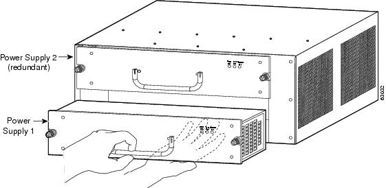
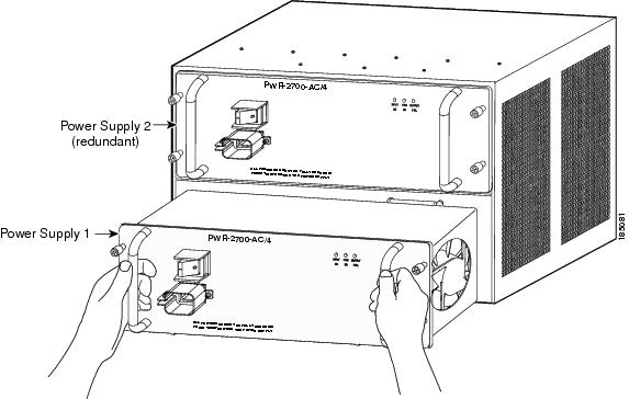
Step 5![]() Grasp the power supply handle with one hand, and slide the power supply part of the way out of the chassis. Place your other hand underneath the power supply, as shown in Figure 1-3,Figure 1-7 and slide the power supply completely out of the chassis.
Grasp the power supply handle with one hand, and slide the power supply part of the way out of the chassis. Place your other hand underneath the power supply, as shown in Figure 1-3,Figure 1-7 and slide the power supply completely out of the chassis.
Step 6![]() If the power supply bay is to remain empty, install a blank power supply filler plate (Cisco part number 800-16727-01 for the Catalyst 6503 and Catalyst 6503-E switches) over the opening, and secure it with the captive installation screws.
If the power supply bay is to remain empty, install a blank power supply filler plate (Cisco part number 800-16727-01 for the Catalyst 6503 and Catalyst 6503-E switches) over the opening, and secure it with the captive installation screws.
Figure 1-1 Catalyst 6503 and Catalyst 6503-E Switches—PEM Location
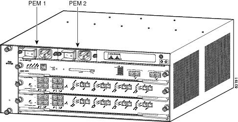
Figure 1-2 Power Supply Captive Installation Screws
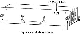
Figure 1-3 Handling an AC-Input Power Supply
Installing a 950 W or 1400 W AC-Input Power Supply
To install an AC-input power supply, follow these steps:
Step 1![]() Ensure that the system (earth) ground connection has been made.
Ensure that the system (earth) ground connection has been made.
For ground connection instructions, see the “Establishing the System Ground” section.
Step 2![]() If necessary, remove the blank power supply filler plate from the chassis power supply bay opening by loosening the captive installation screws.
If necessary, remove the blank power supply filler plate from the chassis power supply bay opening by loosening the captive installation screws.
Step 3![]() Grasp the power supply handle with one hand. Place your other hand underneath the power supply, as shown in Figure 1-3Figure 1-7. Slide the power supply into the power supply bay. Make sure that the power supply is fully seated in the bay.
Grasp the power supply handle with one hand. Place your other hand underneath the power supply, as shown in Figure 1-3Figure 1-7. Slide the power supply into the power supply bay. Make sure that the power supply is fully seated in the bay.
Step 4![]() Securely tighten the power supply captive installation screws.
Securely tighten the power supply captive installation screws.
See Figure 1-2 for the Catalyst 6503 and Catalyst 6503-E switches.

Step 5![]() At the front of the chassis, plug the power cord into the PEM.
At the front of the chassis, plug the power cord into the PEM.
Step 6![]() Connect the other end of the power cord to an AC-input power source.
Connect the other end of the power cord to an AC-input power source.
Step 7![]() Turn the PEM power switch to the On (|) position.
Turn the PEM power switch to the On (|) position.
Step 8![]() Verify the power supply operation by checking that the power supply LEDs are in the following states:
Verify the power supply operation by checking that the power supply LEDs are in the following states:
If the LEDs indicate a power problem, see the “Identifying Startup Problems” section for troubleshooting information.
Removing and Installing the 2700 W AC-Input Power Supply
This section describes how to remove and install the 2700 W AC-input power supply in the Catalyst 6504-E switch. The section is divided into the following topics:
Warning![]() Hazardous voltage or energy is present on the backplane when the system is operating. Use caution when servicing. Statement 1034
Hazardous voltage or energy is present on the backplane when the system is operating. Use caution when servicing. Statement 1034
Note![]() In systems with redundant power supplies, you can replace the faulty supply while the system is operating.
In systems with redundant power supplies, you can replace the faulty supply while the system is operating.
Required Tools
You might need a flat-blade or number 2 Phillips-head screwdriver to loosen or tighten the captive installation screws on the power supply.
Removing a 2700 W AC-Input Power Supply
To remove a 2700 W AC-input power supply, follow these steps:
Step 1![]() Turn the power switch to the off (0) position on the power supply you are removing.
Turn the power switch to the off (0) position on the power supply you are removing.
Step 2![]() Disconnect the power cord from the power source. Do not touch the metal prongs on the power cord while it is still connected to the power supply.
Disconnect the power cord from the power source. Do not touch the metal prongs on the power cord while it is still connected to the power supply.
Step 3![]() Remove the power cord from the power connection on the power supply.
Remove the power cord from the power connection on the power supply.
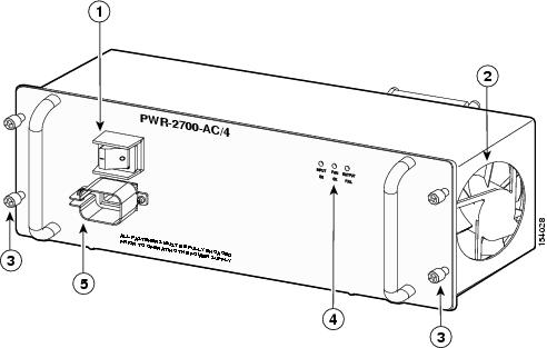
Step 4![]() Loosen the captive installation screws on the power supply. (See Figure 1-4.)
Loosen the captive installation screws on the power supply. (See Figure 1-4.)
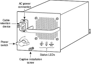
Figure 1-4 2700 W AC-Input Power Supply Captive Installation Screws
|
|
|
||
|
|
|
||
|
|
|
Step 5![]() Grasp both power supply handles, as shown in Figure 1-5,Figure 1-7 and slide the power supply completely out of the chassis.
Grasp both power supply handles, as shown in Figure 1-5,Figure 1-7 and slide the power supply completely out of the chassis.
Figure 1-5 Handling a 2700 W AC-Input Power Supply
Step 6![]() If the power supply bay is to remain empty, install a blank power supply filler plate (Cisco part number 800-16727-01) over the opening and secure it with the captive installation screws.
If the power supply bay is to remain empty, install a blank power supply filler plate (Cisco part number 800-16727-01) over the opening and secure it with the captive installation screws.
Installing a 2700 W AC-Input Power Supply
Warning![]() This product requires short-circuit (overcurrent) protection, to be provided as part of the building installation. Install only in accordance with national and local wiring regulations. Statement 1045
This product requires short-circuit (overcurrent) protection, to be provided as part of the building installation. Install only in accordance with national and local wiring regulations. Statement 1045
To install an AC-input power supply, follow these steps:
Step 1![]() Ensure that the system (earth) ground connection has been made. For ground connection instructions, see the “Establishing the System Ground” section.
Ensure that the system (earth) ground connection has been made. For ground connection instructions, see the “Establishing the System Ground” section.
Step 2![]() If necessary, remove the blank power supply filler plate from the chassis power supply bay opening by loosening the captive installation screws.
If necessary, remove the blank power supply filler plate from the chassis power supply bay opening by loosening the captive installation screws.
Step 3![]() Verify that the power switch on the power supply is in the off (0) position.
Verify that the power switch on the power supply is in the off (0) position.
Step 4![]() Grasp both power supply handles. (See Figure 1-5Figure 1-7.) Slide the power supply into the power supply bay. Make sure that the power supply is fully seated in the bay.
Grasp both power supply handles. (See Figure 1-5Figure 1-7.) Slide the power supply into the power supply bay. Make sure that the power supply is fully seated in the bay.
Step 5![]() Securely tighten the power supply captive installation screws.
Securely tighten the power supply captive installation screws.
Warning![]() Power supply captive installation screws must be tight to ensure protective grounding continuity. Statement 289
Power supply captive installation screws must be tight to ensure protective grounding continuity. Statement 289
Step 6![]() Plug the power cord into the power supply AC-in receptacle.
Plug the power cord into the power supply AC-in receptacle.
Step 7![]() Connect the other end of the power cord to the AC-input power source.
Connect the other end of the power cord to the AC-input power source.
Step 8![]() Turn the switch on the power supply to the on (|) position.
Turn the switch on the power supply to the on (|) position.
Step 9![]() Verify power supply operation by checking that the power supply LEDs are in the following states:
Verify power supply operation by checking that the power supply LEDs are in the following states:
If the LEDs indicate a power problem, see the “Identifying Startup Problems” section for troubleshooting information.
Removing and Installing the 1000 W, 1300 W, 2500 W, 3000 W, 4000 W, 6000 W, and 8700 W AC-Input Power Supplies
This section describes how to remove and install the 1000 W, 1300 W, 2500 W, 3000 W, 4000 W, 6000 W, and 8700 W AC-input power supplies in the Catalyst 6500 series switches that support them. The section is divided into the following topics:
- Required Tools
- Removing the 1000 W, 1300 W, 2500 W, 3000 W, 4000 W, 6000 W, and 8700 W AC-Input Power Supplies
- Installing the 1000 W, 1300 W, 2500 W, 3000 W, 4000 W, 6000 W, and 8700 W AC-Input Power Supplies
All six power supplies have the same basic form factor and are removed and installed using the same procedures.
Note![]() Installing the 8700 W power supply in a Catalyst 6506, Catalyst 6509, or Catalyst 6509-NEB chassis requires you to install the system ground wire on the power supply’s system ground lugs rather than on the chassis system ground pad.
Installing the 8700 W power supply in a Catalyst 6506, Catalyst 6509, or Catalyst 6509-NEB chassis requires you to install the system ground wire on the power supply’s system ground lugs rather than on the chassis system ground pad.
Note![]() In systems with redundant power supplies, you can replace the faulty supply while the system is operating.
In systems with redundant power supplies, you can replace the faulty supply while the system is operating.
Required Tools
You might need a flat-blade or number 2 Phillips-head screwdriver to loosen or tighten the captive installation screws on the power supply.
Removing the 1000 W, 1300 W, 2500 W, 3000 W, 4000 W, 6000 W, and 8700 W AC-Input Power Supplies
Warning![]() Hazardous voltage or energy is present on the backplane when the system is operating. Use caution when servicing. Statement 1034
Hazardous voltage or energy is present on the backplane when the system is operating. Use caution when servicing. Statement 1034
To remove an AC-input power supply, follow these steps:
Step 1![]() Turn the power switch to the off (0) position on the power supply that you are removing. (See Figure 1-6Figure 1-6.) Turning the power switch off also disengages a pawl that unlocks the power supply from the chassis.
Turn the power switch to the off (0) position on the power supply that you are removing. (See Figure 1-6Figure 1-6.) Turning the power switch off also disengages a pawl that unlocks the power supply from the chassis.
Step 2![]() Disconnect the power cord from the power source.
Disconnect the power cord from the power source.
Step 3![]() If you are removing an 8700 W power supply from a Catalyst 6506, Catalyst 6509, or Catalyst 6509-NEB chassis, perform the following substeps to remove the system ground wire from the system ground posts on the power supply:
If you are removing an 8700 W power supply from a Catalyst 6506, Catalyst 6509, or Catalyst 6509-NEB chassis, perform the following substeps to remove the system ground wire from the system ground posts on the power supply:
a.![]() Loosen and remove the two M4 nuts securing the system ground lug to the two system ground posts on the power supply. Set the two nuts aside.
Loosen and remove the two M4 nuts securing the system ground lug to the two system ground posts on the power supply. Set the two nuts aside.
b.![]() Remove and set aside the two washers from each post.
Remove and set aside the two washers from each post.
c.![]() Remove the system ground lug from the system ground posts and set it aside.
Remove the system ground lug from the system ground posts and set it aside.
Step 4![]() Loosen the screw on the cable retention device, and disconnect the power cord from the power supply being removed.
Loosen the screw on the cable retention device, and disconnect the power cord from the power supply being removed.
Note![]() The AC power cord for the 4000 W power supply is hard wired to the power supply and cannot be removed.
The AC power cord for the 4000 W power supply is hard wired to the power supply and cannot be removed.
Step 5![]() Loosen the captive installation screw. (See Figure 1-6.)
Loosen the captive installation screw. (See Figure 1-6.)
Figure 1-6 AC-Input Power Supply Front Panel
Step 6![]() Grasp the power supply handle with one hand, and slide the power supply part of the way out of the chassis. Place your other hand underneath the power supply, as shown in Figure 1-7,Figure 1-7 and slide the power supply completely out of the chassis.
Grasp the power supply handle with one hand, and slide the power supply part of the way out of the chassis. Place your other hand underneath the power supply, as shown in Figure 1-7,Figure 1-7 and slide the power supply completely out of the chassis.
Step 7![]() If the power supply bay is to remain empty, install a blank faceplate (Cisco part number 700-03104-01) over the opening, and secure it with the captive installation screw.
If the power supply bay is to remain empty, install a blank faceplate (Cisco part number 700-03104-01) over the opening, and secure it with the captive installation screw.
Step 8![]() If you have removed an 8700 W power supply from either a Catalyst 6506, Catalyst 6509, or Catalyst 6509-NEB chassis and you have disconnected the system (NEBS) ground from the power supply system ground studs, make sure that you reattach the system ground lug to either the chassis system ground pad if you are not installing a new 8700 W power supply or to the system ground studs if you are installing a new 8700 W power supply.
If you have removed an 8700 W power supply from either a Catalyst 6506, Catalyst 6509, or Catalyst 6509-NEB chassis and you have disconnected the system (NEBS) ground from the power supply system ground studs, make sure that you reattach the system ground lug to either the chassis system ground pad if you are not installing a new 8700 W power supply or to the system ground studs if you are installing a new 8700 W power supply.
Figure 1-7 Handling an AC-Input Power Supply

Installing the 1000 W, 1300 W, 2500 W, 3000 W, 4000 W, 6000 W, and 8700 W AC-Input Power Supplies
To install an AC-input power supply, follow these steps:
Step 1![]() Ensure that the system (earth) ground connection has been made. For ground connection instructions, see the “Establishing the System Ground” section.
Ensure that the system (earth) ground connection has been made. For ground connection instructions, see the “Establishing the System Ground” section.
Note![]() If you are installing an 8700 W power supply in a Catalyst 6506, Catalyst 6509, or Catalyst 6509-NEB chassis, you must install the system (NEBS) ground lug on the system ground studs on the power supply faceplate rather than the system ground pad on the chassis. The increased depth of the 8700 W power supply covers the system (NEBS) ground pad on these three chassis. To install the system ground on the 8700 W power supply, see “Installing the System Ground on an 8700 W Power Supply” section.
If you are installing an 8700 W power supply in a Catalyst 6506, Catalyst 6509, or Catalyst 6509-NEB chassis, you must install the system (NEBS) ground lug on the system ground studs on the power supply faceplate rather than the system ground pad on the chassis. The increased depth of the 8700 W power supply covers the system (NEBS) ground pad on these three chassis. To install the system ground on the 8700 W power supply, see “Installing the System Ground on an 8700 W Power Supply” section.
Step 2![]() If necessary, remove the blank faceplate (Cisco part number 800-27924-xx) from the chassis power supply bay opening by loosening the captive installation screw.
If necessary, remove the blank faceplate (Cisco part number 800-27924-xx) from the chassis power supply bay opening by loosening the captive installation screw.
Step 3![]() Remove the power supply from its shipping packaging.
Remove the power supply from its shipping packaging.
Step 4![]() Verify that the power switch is in the off (0) position on the power supply that you are installing. (See Figure 1-6.)
Verify that the power switch is in the off (0) position on the power supply that you are installing. (See Figure 1-6.)
Step 5![]() Grasp the power supply handle with one hand. Place your other hand underneath the power supply, as shown in Figure 1-7Figure 1-7. Slide the power supply into the power supply bay. Make sure that the power supply is fully seated in the bay.
Grasp the power supply handle with one hand. Place your other hand underneath the power supply, as shown in Figure 1-7Figure 1-7. Slide the power supply into the power supply bay. Make sure that the power supply is fully seated in the bay.
Step 6![]() Tighten the power supply captive installation screw. (See Figure 1-6.)
Tighten the power supply captive installation screw. (See Figure 1-6.)
Step 7![]() If you are installing an 8700 W power supply in a Catalyst 6506, Catalyst 6509, or Catalyst 6509-NEB chassis, install the system (NEBS) ground lug on the power supply system ground studs. For installation instructions, see “Installing the System Ground on an 8700 W Power Supply” section
If you are installing an 8700 W power supply in a Catalyst 6506, Catalyst 6509, or Catalyst 6509-NEB chassis, install the system (NEBS) ground lug on the power supply system ground studs. For installation instructions, see “Installing the System Ground on an 8700 W Power Supply” section
Step 8![]() Plug the power cord into the power supply, and tighten the screw on the cable retention device. Refer to Appendix A for a list of supported AC power cords for your particular AC-input power supply.
Plug the power cord into the power supply, and tighten the screw on the cable retention device. Refer to Appendix A for a list of supported AC power cords for your particular AC-input power supply.
Note![]() The AC power cords for the 4000 W power supply are hard wired to the power supply.
The AC power cords for the 4000 W power supply are hard wired to the power supply.
Step 9![]() Connect the other end of the power cord to an AC-input power source.
Connect the other end of the power cord to an AC-input power source.
Step 10![]() On 8700 W power supplies, there is a relay controller switch located in the lower right quadrant of the power supply faceplate. If you are not using the 8700 W power supply’s remote power-cycling feature or you have the remote power-cycling feature installed and you are using a normally open (NO) relay, make sure that the switch is in the down (DEFAULT) position otherwise the power supply will not power up.
On 8700 W power supplies, there is a relay controller switch located in the lower right quadrant of the power supply faceplate. If you are not using the 8700 W power supply’s remote power-cycling feature or you have the remote power-cycling feature installed and you are using a normally open (NO) relay, make sure that the switch is in the down (DEFAULT) position otherwise the power supply will not power up.
Step 11![]() Turn the power switch to the on (|) position on the power supply. Switching the power switch to on also engages a pawl that locks the power supply in the bay.
Turn the power switch to the on (|) position on the power supply. Switching the power switch to on also engages a pawl that locks the power supply in the bay.
Step 12![]() Verify the power supply operation by ensuring that the power supply front panel LEDs are in these states:
Verify the power supply operation by ensuring that the power supply front panel LEDs are in these states:
Note![]() On the 6000 W and the 8700 W power supplies, there is a separate INPUT LED for each AC power cord. Only the LED for a power supply input that has an AC power cord attached will light.
On the 6000 W and the 8700 W power supplies, there is a separate INPUT LED for each AC power cord. Only the LED for a power supply input that has an AC power cord attached will light.
If the LEDs indicate a power problem, see the “Identifying Startup Problems” section for troubleshooting information.
Removing and Installing the DC-Input Power Supplies
This section covers the DC-input power supply removal and installation procedure for the Catalyst 6500 series switches and is divided into the following topics:
- Removing and Installing a 950 W DC-Input Power Supply
- Removing and Installing a 1300 W or 2500 W DC-Input Power Supply
- Removing and Installing the 2700 W DC-Input Power Supply
- Removing and Installing a 4000 W DC-Input Power Supply
Note![]() The DC return is to remain isolated from the system frame and the chassis (DC-I).
The DC return is to remain isolated from the system frame and the chassis (DC-I).
Removing and Installing a 950 W DC-Input Power Supply
This section describes how to remove and install the 950 W and 1400 W AC-input power supplies for the Catalyst 6503 and the Catalyst 6503-E switches. The section is divided into the following topics:
Note![]() The 950 W DC-input power supply can be installed in the Catalyst 6503 and the Catalyst 6503-E switch chassis only.
The 950 W DC-input power supply can be installed in the Catalyst 6503 and the Catalyst 6503-E switch chassis only.
Tools Required
You might need a flat-blade or number 2 Phillips-head screwdriver to loosen or tighten the captive installation screws on the power supply.
Removing a 950 W DC-Input Power Supply
Warning![]() Before performing any of the following procedures, ensure that power is removed from the DC circuits. To ensure that all power is removed, locate the circuit breakers or fuses on the DC power lines that service the DC circuits. Turn OFF the DC power line circuit breakers and remove the DC power line fuses. Statement 322
Before performing any of the following procedures, ensure that power is removed from the DC circuits. To ensure that all power is removed, locate the circuit breakers or fuses on the DC power lines that service the DC circuits. Turn OFF the DC power line circuit breakers and remove the DC power line fuses. Statement 322
Warning![]() Hazardous voltage or energy is present on the backplane when the system is operating. Use caution when servicing. Statement 1034
Hazardous voltage or energy is present on the backplane when the system is operating. Use caution when servicing. Statement 1034
To remove a DC-input power supply, follow these steps:
Step 1![]() Identify which PEM is connected to the power supply you are removing (PEM 1 or PEM 2). Verify that the source power is off to the circuit that is connected to that PEM.
Identify which PEM is connected to the power supply you are removing (PEM 1 or PEM 2). Verify that the source power is off to the circuit that is connected to that PEM.
Figure 1-8 shows the location of the DC-input PEMs on the Catalyst 6503 switch chassis.
Note![]() The system (NEBS) ground serves as the primary safety ground for the Catalyst 6503 and Catalyst 6503-E chassis that are equipped with DC-input power supplies. The DC-input power supplies for these chassis do not have a separate ground. Make sure that the chassis you are working on has the system (NEBS) ground installed.
The system (NEBS) ground serves as the primary safety ground for the Catalyst 6503 and Catalyst 6503-E chassis that are equipped with DC-input power supplies. The DC-input power supplies for these chassis do not have a separate ground. Make sure that the chassis you are working on has the system (NEBS) ground installed.
Step 2![]() Loosen the captive installation screws on the power supply. (See Figure 1-9.)
Loosen the captive installation screws on the power supply. (See Figure 1-9.)
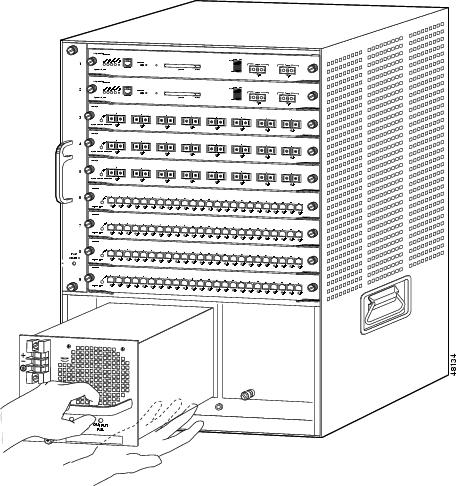
Step 3![]() Grasp the power supply handle with one hand, and slide the power supply part of the way out of the chassis. Place your other hand underneath the power supply, as shown in Figure 1-10,Figure 1-7 and slide the power supply completely out of the chassis.
Grasp the power supply handle with one hand, and slide the power supply part of the way out of the chassis. Place your other hand underneath the power supply, as shown in Figure 1-10,Figure 1-7 and slide the power supply completely out of the chassis.
Step 4![]() If the power supply bay is to remain empty, install a blank power supply filler plate (Cisco part number 800-16727-01) over the opening, and secure it with the captive installation screws.
If the power supply bay is to remain empty, install a blank power supply filler plate (Cisco part number 800-16727-01) over the opening, and secure it with the captive installation screws.
Figure 1-8 Catalyst 6503 Switch—DC-Input PEM Location
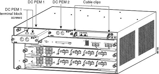
Figure 1-9 950 W DC-Input Power Supply Captive Installation Screws
Figure 1-10 Catalyst 6503 Switch—Handling a DC-Input Power Supply
Installing a 950 W DC-Input Power Supply
Warning![]() Before performing any of the following procedures, ensure that power is removed from the DC circuits. To ensure that all power is removed, locate the circuit breakers or fuses on the DC power lines that service the DC circuits. Turn OFF the DC power line circuit breakers and remove the DC power line fuses. Statement 322
Before performing any of the following procedures, ensure that power is removed from the DC circuits. To ensure that all power is removed, locate the circuit breakers or fuses on the DC power lines that service the DC circuits. Turn OFF the DC power line circuit breakers and remove the DC power line fuses. Statement 322
To install a 950 W DC-input power supply, follow these steps:
Step 1![]() Ensure that the system (earth) ground connection has been made. For ground connection installation instructions, see the “Establishing the System Ground” section.
Ensure that the system (earth) ground connection has been made. For ground connection installation instructions, see the “Establishing the System Ground” section.
Note![]() The system (NEBS) ground serves as the primary safety ground for the Catalyst 6503 and Catalyst 6503-E chassis that are equipped with DC-input power supplies. The DC-input power supplies for these chassis do not have a separate ground. Make sure that the chassis you are working on has the system (NEBS) ground installed.
The system (NEBS) ground serves as the primary safety ground for the Catalyst 6503 and Catalyst 6503-E chassis that are equipped with DC-input power supplies. The DC-input power supplies for these chassis do not have a separate ground. Make sure that the chassis you are working on has the system (NEBS) ground installed.
Step 2![]() Verify that power is off to the DC circuit connected to the DC PEM for the power supply that you are installing. As an added precaution, place the appropriate safety flag and lockout devices at the source power circuit breaker, or place a piece of adhesive tape over the circuit breaker handle to prevent accidental power restoration while you are working on the circuit.
Verify that power is off to the DC circuit connected to the DC PEM for the power supply that you are installing. As an added precaution, place the appropriate safety flag and lockout devices at the source power circuit breaker, or place a piece of adhesive tape over the circuit breaker handle to prevent accidental power restoration while you are working on the circuit.
Step 3![]() Grasp the power supply handle with one hand. Place your other hand underneath the power supply, as shown in Figure 1-10Figure 1-7. Slide the power supply into the power supply bay. Make sure that the power supply is fully seated in the bay.
Grasp the power supply handle with one hand. Place your other hand underneath the power supply, as shown in Figure 1-10Figure 1-7. Slide the power supply into the power supply bay. Make sure that the power supply is fully seated in the bay.
Step 4![]() Tighten the power supply captive installation screws. (See Figure 1-9.)
Tighten the power supply captive installation screws. (See Figure 1-9.)
Step 5![]() Verify that all connections to the DC PEM are secure.
Verify that all connections to the DC PEM are secure.
Step 6![]() Remove any safety flags, lockout devices, or tape from the circuit breaker switch handle, and restore power by moving the circuit breaker switch handle to the On (|) position.
Remove any safety flags, lockout devices, or tape from the circuit breaker switch handle, and restore power by moving the circuit breaker switch handle to the On (|) position.
Step 7![]() Verify the power supply operation by ensuring that the power supply front panel LEDs are in the following states:
Verify the power supply operation by ensuring that the power supply front panel LEDs are in the following states:
If the LEDs indicate a power problem, see the “Identifying Startup Problems” section.
Removing and Installing a 1300 W or 2500 W DC-Input Power Supply
This section covers the power supply removal and installation procedures for the 1300 W and the 2500 W DC-input power supplies and is divided into the following topics:
Required Tools
Use a flat-blade or number 2 Phillips-head screwdriver to perform these procedures. You might also need cutters to cut any cable ties that are installed on the power supply.
Removing a 1300 W or 2500 W DC-Input Power Supply
Warning![]() Before performing any of the following procedures, ensure that power is removed from the DC circuits. To ensure that all power is removed, locate the circuit breakers or fuses on the DC power lines that service the DC circuits. Turn OFF the DC power line circuit breakers and remove the DC power line fuses. Statement 322
Before performing any of the following procedures, ensure that power is removed from the DC circuits. To ensure that all power is removed, locate the circuit breakers or fuses on the DC power lines that service the DC circuits. Turn OFF the DC power line circuit breakers and remove the DC power line fuses. Statement 322
Warning![]() Hazardous voltage or energy is present on the backplane when the system is operating. Use caution when servicing. Statement 1034
Hazardous voltage or energy is present on the backplane when the system is operating. Use caution when servicing. Statement 1034
Warning![]() When installing or replacing the unit, the ground connection must always be made first and disconnected last. Statement 1046
When installing or replacing the unit, the ground connection must always be made first and disconnected last. Statement 1046
To remove a DC-input power supply, follow these steps:
Step 1![]() Verify that power is off to the DC circuit on the power supply that you are removing. As an added precaution, place the appropriate safety flag and lockout devices at the source power circuit breaker, or place a piece of adhesive tape over the circuit breaker handle to prevent accidental power restoration while you are working on the circuit.
Verify that power is off to the DC circuit on the power supply that you are removing. As an added precaution, place the appropriate safety flag and lockout devices at the source power circuit breaker, or place a piece of adhesive tape over the circuit breaker handle to prevent accidental power restoration while you are working on the circuit.
Step 2![]() Turn the power switch to the off (0) position on the power supply that you are removing. Turning the power switch off also disengages a pawl that unlocks the power supply from the chassis.
Turn the power switch to the off (0) position on the power supply that you are removing. Turning the power switch off also disengages a pawl that unlocks the power supply from the chassis.
See Figure 1-11 for the 1300 W DC power supply or Figure 1-12 for the 2500 W DC power supply.
Step 3![]() Remove the two screws securing the terminal block cover, and slide the cover off the terminal block.
Remove the two screws securing the terminal block cover, and slide the cover off the terminal block.
See Figure 1-11 for the 1300 W DC power supply or Figure 1-12 for the 2500 W DC power supply.
Step 4![]() Disconnect the source DC cable lugs from the terminal block (see Figure 1-13 for the 1300 W DC power supply or Figure 1-14 for the 2500 W DC power supply) in this order:
Disconnect the source DC cable lugs from the terminal block (see Figure 1-13 for the 1300 W DC power supply or Figure 1-14 for the 2500 W DC power supply) in this order:
Note![]() The terminals on the 1300 W DC power supply DC power cable terminal block are labeled (from top to bottom) +, –, ground. The terminals on the 2500 W DC power supply DC power cable terminal block are labeled (from top to bottom) –, +, ground.
The terminals on the 1300 W DC power supply DC power cable terminal block are labeled (from top to bottom) +, –, ground. The terminals on the 2500 W DC power supply DC power cable terminal block are labeled (from top to bottom) –, +, ground.
Step 5![]() Loosen the captive installation screw on the power supply.
Loosen the captive installation screw on the power supply.
See Figure 1-13 for the 1300 W DC power supply or Figure 1-14 for the 2500 W DC power supply.
Step 6![]() Grasp the power supply handle with one hand, and slide the power supply halfway out of the chassis. Place your other hand underneath the power supply, as shown in Figure 1-15Figure 1-15, and slide the power supply completely out of the chassis. Set the power supply aside.
Grasp the power supply handle with one hand, and slide the power supply halfway out of the chassis. Place your other hand underneath the power supply, as shown in Figure 1-15Figure 1-15, and slide the power supply completely out of the chassis. Set the power supply aside.
Step 7![]() If the power supply bay is to remain empty, install a blank faceplate (Cisco part number 700-03104-01) over the opening, and secure it with the captive installation screw.
If the power supply bay is to remain empty, install a blank faceplate (Cisco part number 700-03104-01) over the opening, and secure it with the captive installation screw.
Figure 1-11 DC-Input Power Supply Front Panel (WS-CDC-1300W)

Figure 1-12 DC-Input Power Supply Front Panel (WS-CDC-2500W)
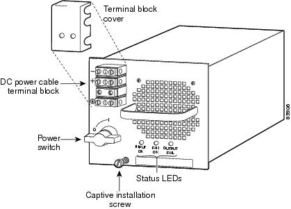
Figure 1-13 DC-Input Wire Connections on the Terminal Block (WS-CDC-1300W)

Figure 1-14 DC-Input Wire Connections on the Terminal Block (WS-CDC-2500W)

Figure 1-15 Handling a DC-Input Power Supply
Installing a 1300 W or 2500 W DC-Input Power Supply
Warning![]() Before performing any of the following procedures, ensure that power is removed from the DC circuits. To ensure that all power is removed, locate the circuit breakers or fuses on the DC power lines that service the DC circuits. Turn OFF the DC power line circuit breakers and remove the DC power line fuses. Statement 322
Before performing any of the following procedures, ensure that power is removed from the DC circuits. To ensure that all power is removed, locate the circuit breakers or fuses on the DC power lines that service the DC circuits. Turn OFF the DC power line circuit breakers and remove the DC power line fuses. Statement 322
Warning![]() When installing or replacing the unit, the ground connection must always be made first and disconnected last. Statement 1046
When installing or replacing the unit, the ground connection must always be made first and disconnected last. Statement 1046
To install a DC-input power supply, follow these steps:
Step 1![]() Ensure that the system (earth) ground connection has been made. For ground connection installation instructions, see the “Establishing the System Ground” section.
Ensure that the system (earth) ground connection has been made. For ground connection installation instructions, see the “Establishing the System Ground” section.
Step 2![]() Verify that power is off to the DC circuit on the power supply that you are installing. As an added precaution, place the appropriate safety flag and lockout devices at the source power circuit breaker, or place a piece of adhesive tape over the circuit breaker handle to prevent accidental power restoration while you are working on the circuit.
Verify that power is off to the DC circuit on the power supply that you are installing. As an added precaution, place the appropriate safety flag and lockout devices at the source power circuit breaker, or place a piece of adhesive tape over the circuit breaker handle to prevent accidental power restoration while you are working on the circuit.
Step 3![]() Verify that the power switch is in the off (0) position on the power supply that you are installing.
Verify that the power switch is in the off (0) position on the power supply that you are installing.
See Figure 1-11 for the 1300 W DC power supply or Figure 1-12 for the 2500 W DC power supply.
Step 4![]() Grasp the power supply handle with one hand, and place your other hand underneath the power supply. Slide the power supply into the power supply bay. Make sure that the power supply is fully seated in the bay. (See Figure 1-15Figure 1-15.)
Grasp the power supply handle with one hand, and place your other hand underneath the power supply. Slide the power supply into the power supply bay. Make sure that the power supply is fully seated in the bay. (See Figure 1-15Figure 1-15.)
Step 5![]() Tighten the power supply captive installation screw. (See Figure 1-11 for the 1300 W DC power supply or Figure 1-12 for the 2500 W DC power supply.)
Tighten the power supply captive installation screw. (See Figure 1-11 for the 1300 W DC power supply or Figure 1-12 for the 2500 W DC power supply.)
Step 6![]() Remove the two screws securing the terminal block cover, and slide the cover off of the terminal block.
Remove the two screws securing the terminal block cover, and slide the cover off of the terminal block.
See Figure 1-11 for the 1300 W DC power supply or Figure 1-12 for the 2500 W DC power supply.
Step 7![]() Attach the appropriate lugs to the DC-input wires. The maximum width of a lug is 0.300 inch (7.6 mm).
Attach the appropriate lugs to the DC-input wires. The maximum width of a lug is 0.300 inch (7.6 mm).
Note![]() The wire should be sized according to local and national installation requirements and electrical codes. Use only copper wire. For North American installations of 2500 WDC-input power supplies, use fine-stranded copper conductors rated for 90°C.
The wire should be sized according to local and national installation requirements and electrical codes. Use only copper wire. For North American installations of 2500 WDC-input power supplies, use fine-stranded copper conductors rated for 90°C.
Step 8![]() Attach the source DC cables to the terminal block (see Figure 1-16 for the 1300 W DC power supply or Figure 1-17 for the 2500 W DC power supply) in this order:
Attach the source DC cables to the terminal block (see Figure 1-16 for the 1300 W DC power supply or Figure 1-17 for the 2500 W DC power supply) in this order:
1.![]() Source ground cable to the power supply terminal block ground post
Source ground cable to the power supply terminal block ground post
2.![]() Source DC negative (–) cable to the power supply terminal block negative (–) post
Source DC negative (–) cable to the power supply terminal block negative (–) post
3.![]() Source DC positive (+) cable to the power supply terminal block positive (+) post
Source DC positive (+) cable to the power supply terminal block positive (+) post
Note![]() The terminals on the 1300 W DC power supply DC power cable terminal block are labeled (from top to bottom) +, –, ground. The terminals on the 2500 W DC power supply DC power cable terminal block are labeled (from top to bottom) –, +, ground.
The terminals on the 1300 W DC power supply DC power cable terminal block are labeled (from top to bottom) +, –, ground. The terminals on the 2500 W DC power supply DC power cable terminal block are labeled (from top to bottom) –, +, ground.
Step 9![]() After ensuring that all wire connections are secure, reinstall the terminal block cover.
After ensuring that all wire connections are secure, reinstall the terminal block cover.
Step 10![]() Remove any safety flag and lockout devices or any tape from the circuit breaker switch handle, and restore power by moving the circuit breaker switch handle to the on (|) position.
Remove any safety flag and lockout devices or any tape from the circuit breaker switch handle, and restore power by moving the circuit breaker switch handle to the on (|) position.
Step 11![]() Turn the power switch to the on (|) position on the power supply. Turning on the power switch also engages a pawl that locks the power supply in the chassis.
Turn the power switch to the on (|) position on the power supply. Turning on the power switch also engages a pawl that locks the power supply in the chassis.
Step 12![]() Verify the power supply operation by ensuring that the power supply front panel LEDs are in these states:
Verify the power supply operation by ensuring that the power supply front panel LEDs are in these states:
If the LEDs indicate a power problem, see the “Identifying Startup Problems” section.
Figure 1-16 DC-Input Power Supply Connectors (WS-CDC-1300W)
Figure 1-17 DC-Input Power Supply Connectors (WS-CDC-2500W)
Removing and Installing the 2700 W DC-Input Power Supply
This section covers the power supply removal and installation procedures for the 2700 W DC-input power supply on the Catalyst 6504-E chassis and is divided into the following topics:
The 2700 W DC-input power supply can operate at either 1350 W or at 2700 W. If you want to operate the power supply at 1350 W, you only need to connect one pair of source DC cables to either the VE-1 or the VE-2 pair of posts on the power supply terminal block. If you want to operate the power supply at 2700 W, you need to connect two pairs of source DC cables to the VE-1 and the VE-2 pairs of posts on the power supply terminal block.
Note![]() For proper 2700 W DC-input redundant power configurations, all of the source DC for one 2700 W DC-input power supply must come from the same battery system (A feed); all of the source DC for the other 2700 W DC-input power supply must come from another battery system (B feed).
For proper 2700 W DC-input redundant power configurations, all of the source DC for one 2700 W DC-input power supply must come from the same battery system (A feed); all of the source DC for the other 2700 W DC-input power supply must come from another battery system (B feed).
Note![]() For multiple DC-input power supplies, each DC input must be protected by a dedicated circuit breaker or a fuse. The circuit breaker or fuse must be sized according to the power supply input rating and the local or national electrical code requirements.
For multiple DC-input power supplies, each DC input must be protected by a dedicated circuit breaker or a fuse. The circuit breaker or fuse must be sized according to the power supply input rating and the local or national electrical code requirements.
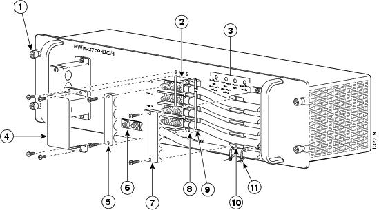
Figure 1-18 shows a 2700 W DC-input power supply (p/n PWR-2700-DC/4) cabled for 2700 W operation with the installation components identified.
Note![]() This illustration shows the source DC cables and the ground cable routed into the power supply from the right side. Two pairs of source DC cables are shown indicating that the power supply is operating at 2700 W. The source DC cables and the ground cable can also be routed out of the left-side of the power supply, if necessary.
This illustration shows the source DC cables and the ground cable routed into the power supply from the right side. Two pairs of source DC cables are shown indicating that the power supply is operating at 2700 W. The source DC cables and the ground cable can also be routed out of the left-side of the power supply, if necessary.
Use this illustration as a reference for identifying components when removing or installing the power supply.
Figure 1-18 2700 W DC-Input Power Supply Features
|
|
|
||
|
|
|
||
|
|
|
||
|
|
|
||
|
|
|
||
|
|
|
Required Tools
The following tools are required for the power supply removal and installation procedures:
- Number 2 Phillips-head screwdriver
- 1/4-inch open-ended wrench or 1/4-inch nutdriver
- Wire cutters to cut the cable tie wraps
Additional tools might be necessary to install the lugs on the source DC and the ground cables. Additionally, the lugs for the source DC cables and the ground cable are not provided; you must obtain them on your own.
Removing a 2700 W DC-Input Power Supply
Warning![]() Before performing any of the following procedures, ensure that power is removed from the DC circuits. To ensure that all power is removed, locate the circuit breakers or fuses on the DC power lines that service the DC circuits. Turn OFF the DC power line circuit breakers and remove the DC power line fuses. Statement 322
Before performing any of the following procedures, ensure that power is removed from the DC circuits. To ensure that all power is removed, locate the circuit breakers or fuses on the DC power lines that service the DC circuits. Turn OFF the DC power line circuit breakers and remove the DC power line fuses. Statement 322
Warning![]() Voltage is present on the backplane when the system is operating. To reduce risk of an electric shock, keep hands and fingers out of the power supply bays and backplane areas. Statement 166
Voltage is present on the backplane when the system is operating. To reduce risk of an electric shock, keep hands and fingers out of the power supply bays and backplane areas. Statement 166
To remove a DC-input power supply, follow these steps:
Step 1![]() Verify that source DC power is off to the DC circuit that feeds the power supply that you are removing. As an added precaution, place the appropriate safety flag and lockout devices at the source DC power circuit breaker, or place a piece of adhesive tape over the circuit breaker handle to prevent accidental power restoration while you are working on the circuit.
Verify that source DC power is off to the DC circuit that feeds the power supply that you are removing. As an added precaution, place the appropriate safety flag and lockout devices at the source DC power circuit breaker, or place a piece of adhesive tape over the circuit breaker handle to prevent accidental power restoration while you are working on the circuit.
Step 2![]() Remove the four screws that secure the terminal block cover (clear plastic) and slide the cover off of the terminal block. Set the cover and the screws aside. (See Figure 1-19.)
Remove the four screws that secure the terminal block cover (clear plastic) and slide the cover off of the terminal block. Set the cover and the screws aside. (See Figure 1-19.)
Step 3![]() Remove the two screws securing the fixed cable guide top half and set the cable guide piece and the screws aside. (See Figure 1-19.)
Remove the two screws securing the fixed cable guide top half and set the cable guide piece and the screws aside. (See Figure 1-19.)
Step 4![]() Remove the two screws securing the detached cable guide top half to the bottom half. Remove both cable guide pieces and the screws and set them aside.
Remove the two screws securing the detached cable guide top half to the bottom half. Remove both cable guide pieces and the screws and set them aside.
Note![]() In addition to the two cable guides, there might be a tie wrap securing the source DC cables and two tie wraps securing the ground cable to the fixed cable guide. You will need to cut all of these tie wraps in order to free the source DC cables and the ground cable for removal.
In addition to the two cable guides, there might be a tie wrap securing the source DC cables and two tie wraps securing the ground cable to the fixed cable guide. You will need to cut all of these tie wraps in order to free the source DC cables and the ground cable for removal.
Figure 1-19 Removing the Terminal Block Cover and the Cable Guides

|
|
|
||
|
|
|
||
|
|
|
Step 5![]() Disconnect the DC-input cables from the terminal block (see Figure 1-20) in this order:
Disconnect the DC-input cables from the terminal block (see Figure 1-20) in this order:
- Positive (+) source DC cable from the +VE-1 terminal block post
- Negative (-) source DC cable from the –VE-1 terminal block post
Note![]() If you have a second pair of source DC cables attached to the VE-2 terminal block posts, you need to remove the second positive (+) and negative (–) source DC cables, in that order, before you remove the ground cable.
If you have a second pair of source DC cables attached to the VE-2 terminal block posts, you need to remove the second positive (+) and negative (–) source DC cables, in that order, before you remove the ground cable.
Save the 1/4-20 nut and the split-ring washer from each terminal block post and set them aside.
Warning![]() When installing the unit, always make the ground connection first and disconnect it last. Statement 42
When installing the unit, always make the ground connection first and disconnect it last. Statement 42
Figure 1-20 Disconnecting the Source DC Cables and Ground Cable

Step 6![]() Loosen the four captive installation screws on the power supply.
Loosen the four captive installation screws on the power supply.
Step 7![]() Grasp both power supply handles, as shown in Figure 1-21,Figure 1-7 and slide the power supply completely out of the chassis and set it aside.
Grasp both power supply handles, as shown in Figure 1-21,Figure 1-7 and slide the power supply completely out of the chassis and set it aside.
Figure 1-21 Handling a DC-Input Power Supply
Step 8![]() If the power supply bay is to remain empty, install a blank power supply filler plate (Cisco part number 700-03104-01) over the opening, and secure it with the captive installation screws.
If the power supply bay is to remain empty, install a blank power supply filler plate (Cisco part number 700-03104-01) over the opening, and secure it with the captive installation screws.
Installing a 2700 W DC-Input Power Supply
This section provides the procedures for installing a 2700 W DC-input power supply in the Catalyst 6504-E switch chassis. The 2700 W DC-input power supply can operate at either 1350 W or at 2700 W. If you want to operate the power supply at 1350 W you only need to connect one pair of source DC cables to either the VE-1 or the VE-2 lugs on the power supply terminal block. If you want to operate the power supply at 2700 W, you need to connect two pairs of source DC cables to the VE-1 and the VE-2 lugs on the power supply terminal block.
Warning![]() Before performing any of the following procedures, ensure that power is removed from the DC circuits. To ensure that all power is removed, locate the circuit breakers or fuses on the DC power lines that service the DC circuits. Turn OFF the DC power line circuit breakers and remove the DC power line fuses. Statement 322
Before performing any of the following procedures, ensure that power is removed from the DC circuits. To ensure that all power is removed, locate the circuit breakers or fuses on the DC power lines that service the DC circuits. Turn OFF the DC power line circuit breakers and remove the DC power line fuses. Statement 322
Note![]() For proper 2700 W DC-input redundant power configurations, all of the source DC for one 2700 W DC-input power supply must come from the same battery system (A feed); all of the source DC for the other 2700 W DC-input power supply must come from another battery system (B feed).
For proper 2700 W DC-input redundant power configurations, all of the source DC for one 2700 W DC-input power supply must come from the same battery system (A feed); all of the source DC for the other 2700 W DC-input power supply must come from another battery system (B feed).
Note![]() For multiple DC-input power supplies, each DC input must be protected by a dedicated circuit breaker or a fuse. The circuit breaker or fuse must be sized according to the power supply input rating and the local or national electrical code requirements.
For multiple DC-input power supplies, each DC input must be protected by a dedicated circuit breaker or a fuse. The circuit breaker or fuse must be sized according to the power supply input rating and the local or national electrical code requirements.
To install the 2700 W DC-input power supply in the Catalyst 6504-E chassis and cable it to source DC, follow these steps:
Step 1![]() Ensure that the system (earth) ground connection has been made. For system ground connection installation instructions, see the “Establishing the System Ground” section.
Ensure that the system (earth) ground connection has been made. For system ground connection installation instructions, see the “Establishing the System Ground” section.
Step 2![]() Remove the power supply from its shipping container and remove any packaging material.
Remove the power supply from its shipping container and remove any packaging material.
Step 3![]() Locate the plastic bags that accompanied the power supply and set them aside. One bag contains one source DC cable guide, terminal block cover (plastic) with four screws, and two cable ties. The other plastic bag contains the 1/4-20 nuts and lock-washers for the terminal posts. You will use these items later in the procedure.
Locate the plastic bags that accompanied the power supply and set them aside. One bag contains one source DC cable guide, terminal block cover (plastic) with four screws, and two cable ties. The other plastic bag contains the 1/4-20 nuts and lock-washers for the terminal posts. You will use these items later in the procedure.
Step 4![]() Verify that source DC power is off to the DC circuit that feeds the power supply that you are installing. As an added precaution, place the appropriate safety flag and lockout devices at the source DC circuit breaker, or place a piece of adhesive tape over the circuit breaker handle to prevent accidental power restoration while you are working on the circuit.
Verify that source DC power is off to the DC circuit that feeds the power supply that you are installing. As an added precaution, place the appropriate safety flag and lockout devices at the source DC circuit breaker, or place a piece of adhesive tape over the circuit breaker handle to prevent accidental power restoration while you are working on the circuit.
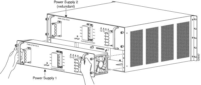
Step 5![]() Grasp both power supply handles, as shown in Figure 1-22Figure 1-7. Slide the power supply into the power supply bay. Make sure that the power supply is fully seated in the bay. Tighten the four captive installation screws.
Grasp both power supply handles, as shown in Figure 1-22Figure 1-7. Slide the power supply into the power supply bay. Make sure that the power supply is fully seated in the bay. Tighten the four captive installation screws.
Warning![]() Power supply captive installation screws must be tight to ensure protective grounding continuity. Statement 289
Power supply captive installation screws must be tight to ensure protective grounding continuity. Statement 289
Figure 1-22 Installing the Power Supply in the Chassis
Step 6![]() Determine whether you will be routing the source DC cables on the left- or right-side of the power supply. Loosen and remove the two screws securing the top half of the fixed cable guide on the side you will be routing the source DC cables. Remove the top half of the cable guide and set it and the screws aside.
Determine whether you will be routing the source DC cables on the left- or right-side of the power supply. Loosen and remove the two screws securing the top half of the fixed cable guide on the side you will be routing the source DC cables. Remove the top half of the cable guide and set it and the screws aside.
Step 7![]() Attach the appropriate size and type of lugs to the source DC cables and the ground cable.
Attach the appropriate size and type of lugs to the source DC cables and the ground cable.
The maximum width of a lug is 0.300 inch (7.6 mm). The source DC cables and the ground cable must be sized according to local and national installation requirements. Use only copper wire. The power supply terminal block lug opening width is 0.62 inch (15.8 mm). The terminal posts are centered 0.63 inches (15.88 mm) apart and have a 1/4-20 thread. We recommend that you use an appropriately sized industry standard 2-hole, standard barrel compression lug. The power supply ground posts also have 1/4-20 threads and require two 1/4-inch split-ring washers and two 1/4-20 hex nuts (one for each post).
Note![]() For 2700 W power supplies, use fine-stranded copper conductors that are rated for 90°C Celsius for North American installations.
For 2700 W power supplies, use fine-stranded copper conductors that are rated for 90°C Celsius for North American installations.
Note![]() For proper 2700 W DC-input redundant power configurations, all of the source DC for one 2700 W DC-input power supply must come from the same battery system (A feed); all of the source DC for the other 2700 W DC-input power supply must come from another battery system (B feed).
For proper 2700 W DC-input redundant power configurations, all of the source DC for one 2700 W DC-input power supply must come from the same battery system (A feed); all of the source DC for the other 2700 W DC-input power supply must come from another battery system (B feed).
Note![]() For multiple DC-input power supplies, each DC input must be protected by a dedicated circuit breaker or a fuse. The circuit breaker or fuse must be sized according to the power supply input rating and the local or national electrical code requirements.
For multiple DC-input power supplies, each DC input must be protected by a dedicated circuit breaker or a fuse. The circuit breaker or fuse must be sized according to the power supply input rating and the local or national electrical code requirements.
Step 8![]() Connect the source DC cable lugs to the 2700 W power supply terminal block posts (Figure 1-23) in this order:
Connect the source DC cable lugs to the 2700 W power supply terminal block posts (Figure 1-23) in this order:
- Ground cable lug to the ground terminal posts
- Negative (–) source DC cable lug to terminal post –VE-1
- Positive (+) source DC cable lug to terminal post +VE-1
Note![]() If you are only going to install one pair of source DC cables (1350 W operation), you can attach the source DC cables to either the VE-1 or VE-2 pair of terminal posts. Also notice that there is only one ground connection on the power supply faceplate.
If you are only going to install one pair of source DC cables (1350 W operation), you can attach the source DC cables to either the VE-1 or VE-2 pair of terminal posts. Also notice that there is only one ground connection on the power supply faceplate.
Figure 1-23 Attaching the Source DC Cables and the Ground Cable
Position the source DC cables in the fixed cable guide. Place the top half of the fixed cable guide over the source DC cables and secure the top half of the cable guide to the bottom half with two screws. Figure 1-24 shows how the source DC cables are routed from the left side of the power supply.
Warning![]() When installing the unit, always make the ground connection first and disconnect it last. Statement 42
When installing the unit, always make the ground connection first and disconnect it last. Statement 42
Step 9![]() Route and secure the ground cable to the fixed cable guide loops with the two cable-ties supplied with the power supply. (See Figure 1-24.)
Route and secure the ground cable to the fixed cable guide loops with the two cable-ties supplied with the power supply. (See Figure 1-24.)
Step 10![]() Position the clear plastic terminal block cover over the terminal block and secure it to the power supply using the four supplied screws. (See Figure 1-24.)
Position the clear plastic terminal block cover over the terminal block and secure it to the power supply using the four supplied screws. (See Figure 1-24.)
Figure 1-24 Securing the Cables to the Cable Guides

Step 11![]() Install the detached source DC cable guide that is supplied with the power supply (see Figure 1-25):
Install the detached source DC cable guide that is supplied with the power supply (see Figure 1-25):
a.![]() Position the thicker half of the cable guide under the two or four source DC cables and align the cables with the grooves in the cable guide. The cable guide should be placed between the terminal block and the fixed cable guide.
Position the thicker half of the cable guide under the two or four source DC cables and align the cables with the grooves in the cable guide. The cable guide should be placed between the terminal block and the fixed cable guide.
b.![]() Place the upper half of the cable guide over the source DC cables and secure the two halves of the cable guide together with the two supplied screws. Do not tighten the screws at this time.
Place the upper half of the cable guide over the source DC cables and secure the two halves of the cable guide together with the two supplied screws. Do not tighten the screws at this time.
c.![]() Slide the cable guide toward the terminal block and position it as close to the terminal block as possible.
Slide the cable guide toward the terminal block and position it as close to the terminal block as possible.
d.![]() Tighten the two cable guide screws.
Tighten the two cable guide screws.
e.![]() Place a tie wrap around the source DC cables near the detached cable guide. Position the tie wrap next to the detached cable guide and tighten the tie wrap securely. Make sure that the detached cable guide cannot slide away from the terminal block.
Place a tie wrap around the source DC cables near the detached cable guide. Position the tie wrap next to the detached cable guide and tighten the tie wrap securely. Make sure that the detached cable guide cannot slide away from the terminal block.
Figure 1-25 Installing the Detached Source DC Cable Guide

|
|
|
Step 12![]() Remove the warning flags and cautionary tape from the source DC mains and switch the source DC on.
Remove the warning flags and cautionary tape from the source DC mains and switch the source DC on.
Step 13![]() Verify the power supply operation by checking that the power supply front panel LEDs are in the following states:
Verify the power supply operation by checking that the power supply front panel LEDs are in the following states:
- INPUT 1 OK LED—If you have source DC cables attached to the VE-1 pair of power supply inputs, verify that the LED is green, otherwise the LED should not be lit.
- INPUT 2 OK LED—If you have source DC cables attached to the VE-2 pair of power supply inputs, verify that the LED is green, otherwise the LED should not be lit.
- FAN OK LED is green.
- OUTPUT FAIL LED is not lit.
If the LEDs indicate a power problem, see the “Identifying Startup Problems” section.
Removing and Installing a 4000 W DC-Input Power Supply
This section covers the power supply removal and installation procedures for the 4000 W DC-input power supply and is divided into the following topics:
Note![]() For proper 4000 W DC-input redundant power configurations, all of the source DC for one 4000 W DC-input power supply must come from the same battery system (A feed); all of the source DC for the other 4000 W DC-input power supply must come from another battery system (B feed).
For proper 4000 W DC-input redundant power configurations, all of the source DC for one 4000 W DC-input power supply must come from the same battery system (A feed); all of the source DC for the other 4000 W DC-input power supply must come from another battery system (B feed).
The 4000 W DC-input power supply can operate at either 2700 W or at 4000 W. If you want to operate the power supply at 2700 W, you need to connect two pairs of source DC cables to the VE-1 and the VE-2 posts on the power supply terminal block. If you want to operate the power supply at 4000 W, you need to connect a third pair of source DC cables to the VE-3 terminal block posts.
Note![]() For multiple DC-input power supplies, each DC input must be protected by a dedicated circuit breaker or a fuse. The circuit breaker or fuse must be sized according to the power supply input rating and the local or national electrical code requirements.
For multiple DC-input power supplies, each DC input must be protected by a dedicated circuit breaker or a fuse. The circuit breaker or fuse must be sized according to the power supply input rating and the local or national electrical code requirements.
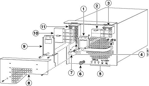
Figure 1-26 shows the features on a 4000 W DC-input power supply. Use the illustration for reference as you remove and install the power supply.
Figure 1-26 4000-W DC-Input Power Supply Installation Features
|
|
|
||
|
|
|
||
|
|
|
||
|
|
|
||
|
|
|
||
|
|
|
Required Tools
The following tools are required for the power supply removal and installation procedures:
- Number 2 Phillips-head screwdriver
- 1/4-inch open-ended wrench or 1/4-inch nutdriver
- Wire cutters to cut the cable tie-wraps
Additional tools might be necessary to install the lugs on the source DC and the ground cables. Additionally, the lugs for the source DC cables and the ground cable are not provided; you must obtain them on your own.
Removing a 4000 W DC-Input Power Supply
Warning![]() When installing the unit, always make the ground connection first and disconnect it last. Statement 42
When installing the unit, always make the ground connection first and disconnect it last. Statement 42
Warning![]() Before performing any of the following procedures, ensure that power is removed from the DC circuits. To ensure that all power is removed, locate the circuit breakers or fuses on the DC power lines that service the DC circuits. Turn OFF the DC power line circuit breakers and remove the DC power line fuses. Statement 322
Before performing any of the following procedures, ensure that power is removed from the DC circuits. To ensure that all power is removed, locate the circuit breakers or fuses on the DC power lines that service the DC circuits. Turn OFF the DC power line circuit breakers and remove the DC power line fuses. Statement 322
Warning![]() Voltage is present on the backplane when the system is operating. To reduce risk of an electric shock, keep hands and fingers out of the power supply bays and backplane areas. Statement 166
Voltage is present on the backplane when the system is operating. To reduce risk of an electric shock, keep hands and fingers out of the power supply bays and backplane areas. Statement 166
To remove a 4000 W DC-input power supply, follow these steps:
Step 1![]() Verify that power is off to the DC circuit that feeds power to the power supply that you are removing. As an added precaution, place the appropriate safety flag and lockout devices at the source power circuit breaker, or place a piece of adhesive tape over the circuit breaker handle to prevent accidental power restoration while you are working on the circuit.
Verify that power is off to the DC circuit that feeds power to the power supply that you are removing. As an added precaution, place the appropriate safety flag and lockout devices at the source power circuit breaker, or place a piece of adhesive tape over the circuit breaker handle to prevent accidental power restoration while you are working on the circuit.
Step 2![]() Turn the power switch to the off (0) position on the power supply that you are removing. (See Figure 1-26.)
Turn the power switch to the off (0) position on the power supply that you are removing. (See Figure 1-26.)
Turning off the power switch also disengages a pawl that unlocks the power supply from the chassis.
Note![]() Figure 1-26 shows the PWR-4000-DC power supply with an outer terminal block cover. An earlier version of this power supply does not have an outer terminal block cover. To order a retrofit kit containing this cover, use Cisco Systems part number CVR-4000DC-TERM=.
Figure 1-26 shows the PWR-4000-DC power supply with an outer terminal block cover. An earlier version of this power supply does not have an outer terminal block cover. To order a retrofit kit containing this cover, use Cisco Systems part number CVR-4000DC-TERM=.
Step 3![]() Remove the two screws securing the outer terminal block cover. Lift the cover up to detach the two tabs from the slots on the power supply. Remove the cover and set it aside along with the screws. (See Figure 1-26.)
Remove the two screws securing the outer terminal block cover. Lift the cover up to detach the two tabs from the slots on the power supply. Remove the cover and set it aside along with the screws. (See Figure 1-26.)
Step 4![]() Remove the two screws securing the left inner terminal block cover (covering the VE-1/VE-2 terminal block). Lift up on the cover to detach the tab from the slot on the power supply. Remove the cover and set it aside along with the screws.
Remove the two screws securing the left inner terminal block cover (covering the VE-1/VE-2 terminal block). Lift up on the cover to detach the tab from the slot on the power supply. Remove the cover and set it aside along with the screws.
Step 5![]() Remove the one screw securing the right inner terminal block cover (covering the VE-3 terminal block). Lift up on the cover to detach the tab from the slot on the power supply. Remove the cover and set it aside along with the screw.
Remove the one screw securing the right inner terminal block cover (covering the VE-3 terminal block). Lift up on the cover to detach the tab from the slot on the power supply. Remove the cover and set it aside along with the screw.
Step 6![]() Disconnect the source DC cables from the terminal blocks in this order:
Disconnect the source DC cables from the terminal blocks in this order:
1.![]() Positive (+) source DC cables from the +VE-1, +VE-2, and +VE-3 terminal posts
Positive (+) source DC cables from the +VE-1, +VE-2, and +VE-3 terminal posts
2.![]() Negative (–) source DC cables from the –VE-1, –VE-2, and –VE-3 terminal posts
Negative (–) source DC cables from the –VE-1, –VE-2, and –VE-3 terminal posts
3.![]() Ground cable from the ground terminal posts
Ground cable from the ground terminal posts
You must remove all DC-input wiring from both terminal blocks before physically removing the power supply chassis.
Step 7![]() Loosen the captive installation screw on the power supply. (See Figure 1-27.)
Loosen the captive installation screw on the power supply. (See Figure 1-27.)
Step 8![]() Grasp the power supply handle with one hand, and slide the power supply part of the way out of the chassis. Place your other hand underneath the power supply, as shown in Figure 1-28,Figure 1-7 and slide the power supply completely out of the chassis and set it aside.
Grasp the power supply handle with one hand, and slide the power supply part of the way out of the chassis. Place your other hand underneath the power supply, as shown in Figure 1-28,Figure 1-7 and slide the power supply completely out of the chassis and set it aside.
Figure 1-27 Source DC Cable Connections for 4000-W DC-Input Power Supply

Figure 1-28 Handling a 4000 W DC-Input Power Supply

Step 9![]() If the power supply bay is to remain empty, install a blank power supply filler plate (Cisco part number 700-03104-01) over the opening, and secure it with the captive installation screw.
If the power supply bay is to remain empty, install a blank power supply filler plate (Cisco part number 700-03104-01) over the opening, and secure it with the captive installation screw.
Installing a 4000 W DC-Input Power Supply
The 4000 W DC-input power supply can be wired for either 2700 W or 4000 W operation. The type of power output from the power supply determines the number of source DC power cables and how they are routed and connected in the chassis. Refer to Table 1-2 to select the appropriate installation procedure for your site.
|
|
|
|
|---|---|---|
“Installing the 4000 W Power Supply (Wiring for 2700 W Operation; Left Power Bay)” section |
||
A redundant (second) 4000 W power supply in the right power supply bay |
“Installing the 4000 W Power Supply (Wiring for 2700 W Operation; Right Power Bay)” section |
|
“Installing the 4000 W Power Supply (Wiring for 4000 W Operation; Left Power Bay)” section |
||
A redundant (second) 4000 W power supply in the right power supply bay |
“Installing the 4000 W Power Supply (Wiring for 4000 W Operation; Right Power Bay)” section |
When installing a 4000 W DC-input power supply, observe the following guidelines:
- For proper 4000 W DC-input redundant power configuration, all source DC cables for one 4000 W DC-input power supply must come from the same battery system (A feed), and all source DC cables for the second 4000 W DC-input power supply must come from a different battery system (B feed).
Note![]() For multiple DC-input power supplies, each DC input must be protected by a dedicated circuit breaker or a fuse. The circuit breaker or fuse must be sized according to the power supply input rating and the local or national electrical code requirements.
For multiple DC-input power supplies, each DC input must be protected by a dedicated circuit breaker or a fuse. The circuit breaker or fuse must be sized according to the power supply input rating and the local or national electrical code requirements.
- The 4000 W DC-input power supply is designed to operate at either 2700 W or 4000 W. To operate the power supply at 2700 W, you can wire any two positive (+) negative (–) terminal pairs (VE-1 and VE-2, VE-2 and VE-3, or VE-1 and VE-3). To operate the power supply at 4000 W, you must wire all three terminal pairs.
Note![]() The 4000 W DC-input power supply does not operate with only one pair of source DC cables connected.
The 4000 W DC-input power supply does not operate with only one pair of source DC cables connected.
- For a single 4000 W DC-input power supply installation, install the power supply in the left-side power bay (POWER 1).
Warning![]() Before performing any of the following procedures, ensure that power is removed from the DC circuits. To ensure that all power is removed, locate the circuit breakers or fuses on the DC power lines that service the DC circuits. Turn OFF the DC power line circuit breakers and remove the DC power line fuses. Statement 322
Before performing any of the following procedures, ensure that power is removed from the DC circuits. To ensure that all power is removed, locate the circuit breakers or fuses on the DC power lines that service the DC circuits. Turn OFF the DC power line circuit breakers and remove the DC power line fuses. Statement 322
Warning![]() Power supply captive installation screws must be tight to ensure protective grounding continuity. Statement 289
Power supply captive installation screws must be tight to ensure protective grounding continuity. Statement 289
Refer to Figure 1-26 for a front view of the power supply with the major features called out.
Note![]() Figure 1-26 shows the PWR-4000-DC power supply with an outer terminal block cover. An earlier version of this power supply does not have an outer terminal block cover. To order a retrofit kit containing this cover, use Cisco Systems part number CVR-4000DC-TERM=.
Figure 1-26 shows the PWR-4000-DC power supply with an outer terminal block cover. An earlier version of this power supply does not have an outer terminal block cover. To order a retrofit kit containing this cover, use Cisco Systems part number CVR-4000DC-TERM=.
Installing the 4000 W Power Supply (Wiring for 2700 W Operation; Left Power Bay)
Refer to Figure 1-26 for item location and identification on the 4000 W DC-input power supply.
Note![]() You should allow a minimum of 2.5 to 3 inches (63.5 mm to 76.2 mm) of space between the side of the power supply and any obstructions (such as the side of an enclosed equipment rack). This space is needed to install and secure the DC-input power cables correctly. Incorrectly routing the DC-input power cables can cause airflow blockage into the power supply and inadequate strain relief in the cables. The exact amount of space required depends upon the gauge and flexibility of the DC-input power cables that you are using.
You should allow a minimum of 2.5 to 3 inches (63.5 mm to 76.2 mm) of space between the side of the power supply and any obstructions (such as the side of an enclosed equipment rack). This space is needed to install and secure the DC-input power cables correctly. Incorrectly routing the DC-input power cables can cause airflow blockage into the power supply and inadequate strain relief in the cables. The exact amount of space required depends upon the gauge and flexibility of the DC-input power cables that you are using.
Note![]() For proper 2700 W redundant power configurations, source DC for one 4000 W DC-input power supply must come from the same battery system (A feed); source DC for the other 4000 W DC-input power supply must come from another battery system (B feed).
For proper 2700 W redundant power configurations, source DC for one 4000 W DC-input power supply must come from the same battery system (A feed); source DC for the other 4000 W DC-input power supply must come from another battery system (B feed).
Note![]() For multiple DC-input power supplies, each DC input must be protected by a dedicated circuit breaker or a fuse. The circuit breaker or fuse must be sized according to the power supply input rating and the local or national electrical code requirements.
For multiple DC-input power supplies, each DC input must be protected by a dedicated circuit breaker or a fuse. The circuit breaker or fuse must be sized according to the power supply input rating and the local or national electrical code requirements.
To install a 4000 W DC-input power supply and wire it for 2700 W operation in the left power bay (POWER 1), follow these steps:
Step 1![]() Ensure that the system (earth) ground connection has been made.
Ensure that the system (earth) ground connection has been made.
For ground connection installation instructions, see the “Establishing the System Ground” section.
Step 2![]() Remove the power supply from its shipping container and remove any packaging.
Remove the power supply from its shipping container and remove any packaging.
Step 3![]() Verify that source DC power is off to the DC circuit that feeds the power supply that you are installing. As an added precaution, place the appropriate safety flag and lockout devices at the source power circuit breaker, or place a piece of adhesive tape over the circuit breaker handle to prevent accidental power restoration while you are working on the circuit.
Verify that source DC power is off to the DC circuit that feeds the power supply that you are installing. As an added precaution, place the appropriate safety flag and lockout devices at the source power circuit breaker, or place a piece of adhesive tape over the circuit breaker handle to prevent accidental power restoration while you are working on the circuit.
Step 4![]() Prepare the source DC power cables by attaching the appropriately sized lugs.
Prepare the source DC power cables by attaching the appropriately sized lugs.
The power supply terminal block lug opening width is 0.62 inch (15.8 mm). The terminal posts are centered 0.63 inches (15.88 mm) apart and have a 1/4-20 thread. We recommend that you use an appropriately sized industry standard 2-hole, standard barrel compression lug. (See Figure 1-29.) The power supply ground posts, located below the terminal block, also have 1/4-20 threads and require two 1/4-inch split-ring washers and two 1/4-20 hex nuts.
The DC-input wires and the DC power supply ground wires should be sized according to the local and national installation requirements. Use only copper wire. For North American installations, use 90°C-rated, fine-strand copper conductors.
Figure 1-29 DC Power Cable Lug
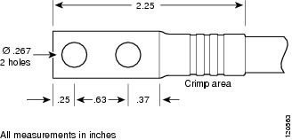
Step 5![]() Grasp the power supply handle with one hand, and place your other hand underneath the power supply. Slide the power supply into the power supply bay. Make sure that the power supply is fully seated in the bay. (See Figure 1-30.)
Grasp the power supply handle with one hand, and place your other hand underneath the power supply. Slide the power supply into the power supply bay. Make sure that the power supply is fully seated in the bay. (See Figure 1-30.)
Figure 1-30 Handling a 4000 W DC-Input Power Supply
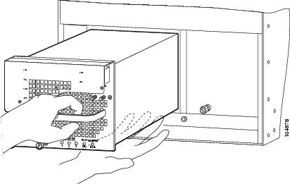
Step 6![]() Tighten the power supply captive installation screw. (See Figure 1-26.)
Tighten the power supply captive installation screw. (See Figure 1-26.)
Step 7![]() Remove the two screws that secure the outer terminal block cover. Lift the cover up to detach the cover tabs from the slots in the power supply. Set the cover and the screws aside.
Remove the two screws that secure the outer terminal block cover. Lift the cover up to detach the cover tabs from the slots in the power supply. Set the cover and the screws aside.
Step 8![]() Remove the two screws that secure the left inner terminal block cover. Lift up on the cover to detach the cover tab from the slot in the power supply. Set the cover and the screws aside.
Remove the two screws that secure the left inner terminal block cover. Lift up on the cover to detach the cover tab from the slot in the power supply. Set the cover and the screws aside.
Step 9![]() Remove the one screw that secures the right inner terminal block cover. Lift up on the cover to detach the cover tab from the slot in the power supply. Set the cover and the screw aside.
Remove the one screw that secures the right inner terminal block cover. Lift up on the cover to detach the cover tab from the slot in the power supply. Set the cover and the screw aside.
Step 10![]() Remove the two plastic insulators from the plastic bag that shipped with the power supply. Position the larger plastic insulator (eight holes) over the eight-post terminal block (VE-1/VE-2). Align the holes in plastic with the terminal block posts. The end flap on the insulator should face away from the DC source cable entry direction.
Remove the two plastic insulators from the plastic bag that shipped with the power supply. Position the larger plastic insulator (eight holes) over the eight-post terminal block (VE-1/VE-2). Align the holes in plastic with the terminal block posts. The end flap on the insulator should face away from the DC source cable entry direction.
Step 11![]() Position the smaller plastic insulator (four holes) over four-post terminal block VE-3. Align the holes in the plastic with the terminal block posts. The end flap on the insulator should face away from the DC source cable entry direction.
Position the smaller plastic insulator (four holes) over four-post terminal block VE-3. Align the holes in the plastic with the terminal block posts. The end flap on the insulator should face away from the DC source cable entry direction.
Step 12![]() Fold the end flaps down on both insulators to cover the open side of the terminal blocks (opposite side from cable entry).
Fold the end flaps down on both insulators to cover the open side of the terminal blocks (opposite side from cable entry).
Note![]() Be sure to place a plastic insulator over both terminal blocks, even if you are not attaching source DC cables to it; this ensures that the plastic insulator is available for future use.
Be sure to place a plastic insulator over both terminal blocks, even if you are not attaching source DC cables to it; this ensures that the plastic insulator is available for future use.
Step 13![]() From the left side of the power supply, connect the power supply ground cable and the source DC cables to the power supply terminal blocks in this order (Figure 1-31):
From the left side of the power supply, connect the power supply ground cable and the source DC cables to the power supply terminal blocks in this order (Figure 1-31):
1.![]() Ground cable lug to the ground terminal posts
Ground cable lug to the ground terminal posts
2.![]() Negative (–) source DC cables to any two pairs of (–) terminal posts (VE-1 and VE-2, VE-1 and VE-3, or VE-2 and VE-3)
Negative (–) source DC cables to any two pairs of (–) terminal posts (VE-1 and VE-2, VE-1 and VE-3, or VE-2 and VE-3)
3.![]() Positive (+) source DC cables to any two pairs of (+) terminal posts (VE-1 and VE-2, VE-1 and VE-3, or VE-2 and VE-3)
Positive (+) source DC cables to any two pairs of (+) terminal posts (VE-1 and VE-2, VE-1 and VE-3, or VE-2 and VE-3)
Figure 1-31 DC-Input Wire Connections for 2700 W Operation (Left-Side Power Bay)
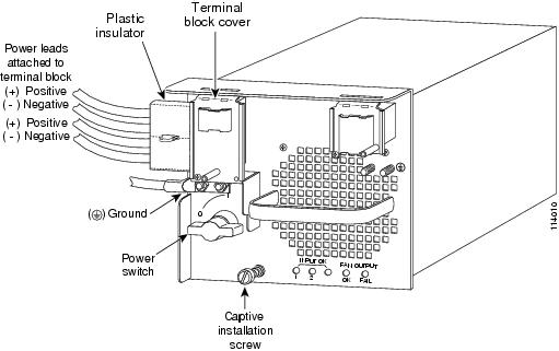
Step 14![]() Wrap the large perforated flaps of the insulators around each pair of source DC cables, inserting each locking tab into the rear of the slot. Pull the tab until the cover is secured around the power cabling trim, and discard excess tab plastic.
Wrap the large perforated flaps of the insulators around each pair of source DC cables, inserting each locking tab into the rear of the slot. Pull the tab until the cover is secured around the power cabling trim, and discard excess tab plastic.
Step 15![]() Position and secure the left inner terminal block cover with two screws. Position and secure the right inner terminal block cover with one screw.
Position and secure the left inner terminal block cover with two screws. Position and secure the right inner terminal block cover with one screw.
Step 16![]() Install and secure the outer terminal block cover with the two screws.
Install and secure the outer terminal block cover with the two screws.
Step 17![]() If you are installing a second power supply operating at 2700 W in the right-side power supply bay, proceed to “Installing the 4000 W Power Supply (Wiring for 2700 W Operation; Right Power Bay)” section; otherwise, go to Step 18.
If you are installing a second power supply operating at 2700 W in the right-side power supply bay, proceed to “Installing the 4000 W Power Supply (Wiring for 2700 W Operation; Right Power Bay)” section; otherwise, go to Step 18.
Step 18![]() After you confirm that all installation steps are completed correctly, remove any safety flags, lockout devices, or adhesive tape from the source DC circuit breakers, and energize the input circuits to the power supplies.
After you confirm that all installation steps are completed correctly, remove any safety flags, lockout devices, or adhesive tape from the source DC circuit breakers, and energize the input circuits to the power supplies.
Step 19![]() Turn the power switch to the on (|) position on the power supply. Turning on the power switch also engages a pawl that locks the power supply in the chassis.
Turn the power switch to the on (|) position on the power supply. Turning on the power switch also engages a pawl that locks the power supply in the chassis.
Step 20![]() Verify the power supply operation by ensuring that the power supply front panel LEDs are in the following states:
Verify the power supply operation by ensuring that the power supply front panel LEDs are in the following states:
- INPUT OK 1 LED—If you have source DC cables attached to the VE-1 pair of power supply inputs, verify that the LED is green. If source DC cables are attached and the LED is not lit, source DC might not be on or the source DC voltage is less than or equal to –33 VDC. If the source DC voltage is between –33 VDC and –40.5 VDC, the LED can be either on, off, or flashing.
- INPUT OK 2 LED—If you have source DC cables attached to the VE-2 pair of power supply inputs, verify that the LED is green. If source DC cables are attached and the LED is not lit, source DC might not be on or the source DC voltage is less than or equal to –33 VDC. If the source DC voltage is between –33 VDC and –40.5 VDC, the LED can be either on, off, or flashing.
- INPUT OK 3 LED—If you have source DC cables attached to the VE-3 pair of power supply inputs, verify that the LED is green. If source DC cables are attached and the LED is not lit, source DC might not be on or the source DC voltage is less than or equal to –33 VDC. If the source DC voltage is between –33 VDC and –40.5 VDC, the LED can be either on, off, or flashing.
- FAN OK LED is green.
- OUTPUT FAIL LED is not lit.
If the LEDs indicate a power problem, see the “Identifying Startup Problems” section.
Installing the 4000 W Power Supply (Wiring for 2700 W Operation; Right Power Bay)
See Figure 1-26 for item location and identification on the 4000 W DC-input power supply.
Note![]() You should allow a minimum of 2.5 to 3 inches (63.5 mm to 76.2 mm) of space between the side of the power supply and any obstructions (such as the side of an enclosed equipment rack). This space is needed to install and secure the DC-input power cables correctly. Incorrectly routing the DC-input power cables can cause airflow blockage into the power supply and inadequate strain relief in the cables. The exact amount of space required depends upon the gauge and flexibility of the DC-input power cables that you are using.
You should allow a minimum of 2.5 to 3 inches (63.5 mm to 76.2 mm) of space between the side of the power supply and any obstructions (such as the side of an enclosed equipment rack). This space is needed to install and secure the DC-input power cables correctly. Incorrectly routing the DC-input power cables can cause airflow blockage into the power supply and inadequate strain relief in the cables. The exact amount of space required depends upon the gauge and flexibility of the DC-input power cables that you are using.
Note![]() For proper 2700 W DC-input redundant power configurations, source DC for one 4000 W DC-input power supply must come from the same battery system (A feed); source DC for the other 4000 W DC-input power supply must come from another battery system (B feed).
For proper 2700 W DC-input redundant power configurations, source DC for one 4000 W DC-input power supply must come from the same battery system (A feed); source DC for the other 4000 W DC-input power supply must come from another battery system (B feed).
Note![]() For multiple DC-input power supplies, each DC input must be protected by a dedicated circuit breaker or a fuse. The circuit breaker or fuse must be sized according to the power supply input rating and the local or national electrical code requirements.
For multiple DC-input power supplies, each DC input must be protected by a dedicated circuit breaker or a fuse. The circuit breaker or fuse must be sized according to the power supply input rating and the local or national electrical code requirements.
To install a 4000 W DC-input power supply and wire it for 2700 W operation in the right power supply bay (POWER 2), follow these steps:
Step 1![]() Ensure that the system (earth) ground connection has been made.
Ensure that the system (earth) ground connection has been made.
For ground connection installation instructions, see the “Establishing the System Ground” section.
Step 2![]() Remove the power supply from its shipping container and remove any packaging.
Remove the power supply from its shipping container and remove any packaging.
Step 3![]() Verify that source DC is off to the DC circuit that feeds the power supply that you are installing. As an added precaution, place the appropriate safety flag and lockout devices at the source power circuit breaker, or place a piece of adhesive tape over the circuit breaker handle to prevent accidental power restoration while you are working on the circuit.
Verify that source DC is off to the DC circuit that feeds the power supply that you are installing. As an added precaution, place the appropriate safety flag and lockout devices at the source power circuit breaker, or place a piece of adhesive tape over the circuit breaker handle to prevent accidental power restoration while you are working on the circuit.
Step 4![]() Prepare the source DC power cables by attaching the appropriately sized lugs.
Prepare the source DC power cables by attaching the appropriately sized lugs.
The power supply terminal block lug opening width is 0.62 inch (15.8 mm). The terminal posts are centered 0.63 inches (15.88 mm) apart and have a 1/4-20 thread. We recommend that you use an appropriately sized industry standard 2-hole, standard barrel compression lug. (See Figure 1-32.) The power supply ground posts, located below the terminal block, also have 1/4-20 threads and require two 1/4-inch split-ring washers and two 1/4-20 hex nuts.
The DC-input wires and the DC power supply ground wires should be sized according to the local and national installation requirements. Use only copper wire. For North American installations, use 90°C-rated, fine-strand copper conductors.
Figure 1-32 DC Power Cable Lug
Step 5![]() Grasp the power supply handle with one hand, and place your other hand underneath the power supply. Slide the supply into the right-side power supply bay. Make sure that the power supply is fully seated in the bay. (See Figure 1-33.)
Grasp the power supply handle with one hand, and place your other hand underneath the power supply. Slide the supply into the right-side power supply bay. Make sure that the power supply is fully seated in the bay. (See Figure 1-33.)
Figure 1-33 Handling a 4000 W DC-Input Power Supply
Step 6![]() Tighten the power supply captive installation screw.
Tighten the power supply captive installation screw.
Step 7![]() Remove the two screws that secure the outer terminal block cover. Lift the cover up to detach the cover tabs from the slots in the power supply. Set the cover and the screws aside.
Remove the two screws that secure the outer terminal block cover. Lift the cover up to detach the cover tabs from the slots in the power supply. Set the cover and the screws aside.
Step 8![]() Remove the two screws that secure the left inner terminal block cover. Lift up on the cover to detach the cover tab from the slot in the power supply. Set the cover and the screws aside.
Remove the two screws that secure the left inner terminal block cover. Lift up on the cover to detach the cover tab from the slot in the power supply. Set the cover and the screws aside.
Step 9![]() Remove the one screw that secures the right inner terminal block cover. Lift up on the cover to detach the cover tab from the slot in the power supply. Set the cover and the screw aside.
Remove the one screw that secures the right inner terminal block cover. Lift up on the cover to detach the cover tab from the slot in the power supply. Set the cover and the screw aside.
Step 10![]() Remove the two plastic insulators from the plastic bag that shipped with the power supply. Position the larger plastic insulator (eight holes) over terminal block VE-1/VE-2. Align the holes in plastic with the terminal block posts. The end flap on the insulator should face away from the DC source cable entry direction.
Remove the two plastic insulators from the plastic bag that shipped with the power supply. Position the larger plastic insulator (eight holes) over terminal block VE-1/VE-2. Align the holes in plastic with the terminal block posts. The end flap on the insulator should face away from the DC source cable entry direction.
Step 11![]() Position the smaller plastic insulator (four holes) over the four-post terminal block VE-3. Align the holes in the plastic with the terminal block posts. The end flap on the insulator should face away from the source DC cable entry direction.
Position the smaller plastic insulator (four holes) over the four-post terminal block VE-3. Align the holes in the plastic with the terminal block posts. The end flap on the insulator should face away from the source DC cable entry direction.
Step 12![]() Fold the end flaps down on both insulators to cover the open side of the terminal block (opposite side from cable entry).
Fold the end flaps down on both insulators to cover the open side of the terminal block (opposite side from cable entry).
Note![]() Be sure to place a plastic insulator over both terminal blocks, even though you might not attach source DC cables to the terminal block; installing both of the insulators ensures that they are available for future use.
Be sure to place a plastic insulator over both terminal blocks, even though you might not attach source DC cables to the terminal block; installing both of the insulators ensures that they are available for future use.
Step 13![]() From the right side of the power supply, connect the power supply ground cable and the source DC cables to the DC-input wires to the terminal block (Figure 1-34) in this order:
From the right side of the power supply, connect the power supply ground cable and the source DC cables to the DC-input wires to the terminal block (Figure 1-34) in this order:
1.![]() Ground cable lug to the ground terminal posts
Ground cable lug to the ground terminal posts
2.![]() Negative (–) source DC cables to any two pairs of (–) terminal posts (VE-1 and VE-2, VE-1 and VE-3, or VE-2 and VE-3)
Negative (–) source DC cables to any two pairs of (–) terminal posts (VE-1 and VE-2, VE-1 and VE-3, or VE-2 and VE-3)
3.![]() Positive (+) source DC cables to any two pairs of (+) terminal posts (VE-1 and VE-2, VE-1 and VE-3, or VE-2 and VE-3)
Positive (+) source DC cables to any two pairs of (+) terminal posts (VE-1 and VE-2, VE-1 and VE-3, or VE-2 and VE-3)
Figure 1-34 DC-Input Wire Connections for 2700 W Operation (Right-Side Power Bay)
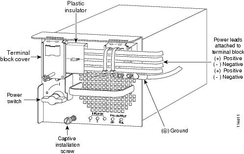
Step 14![]() Wrap the large perforated flaps of the insulators around each pair of source DC cables, inserting each locking tab into the rear of the slot. Pull the tab until the cover is secured around the power cabling trim, and discard excess tab plastic.
Wrap the large perforated flaps of the insulators around each pair of source DC cables, inserting each locking tab into the rear of the slot. Pull the tab until the cover is secured around the power cabling trim, and discard excess tab plastic.
Step 15![]() Position and secure the left inner terminal block cover with two screws. Position and secure the right inner terminal block cover with one screw.
Position and secure the left inner terminal block cover with two screws. Position and secure the right inner terminal block cover with one screw.
Step 16![]() Using the cable tie provided, place the cable tie through the slot at the top of the right terminal block cover, and secure the wiring to the left terminal block.
Using the cable tie provided, place the cable tie through the slot at the top of the right terminal block cover, and secure the wiring to the left terminal block.
Step 17![]() Install and secure outer terminal block cover with the two screws.
Install and secure outer terminal block cover with the two screws.
Step 18![]() After you confirm that all installation steps are completed correctly, remove any safety flags, lockout devices, or adhesive tape from the source DC circuit breakers, and energize the input circuits to the power supplies.
After you confirm that all installation steps are completed correctly, remove any safety flags, lockout devices, or adhesive tape from the source DC circuit breakers, and energize the input circuits to the power supplies.
Step 19![]() Turn the power switch to the on (|) position on the power supply. Turning on the power switch also engages a pawl that locks the power supply in the chassis.
Turn the power switch to the on (|) position on the power supply. Turning on the power switch also engages a pawl that locks the power supply in the chassis.
Step 20![]() Verify the power supply operation by ensuring that the power supply front panel LEDs are in the following states:
Verify the power supply operation by ensuring that the power supply front panel LEDs are in the following states:
- INPUT OK 1 LED—If you have source DC cables attached to the VE-1 pair of power supply inputs, verify that the LED is green. If source DC cables are attached and the LED is not lit, source DC might not be on or the source DC voltage is less than or equal to –33 VDC. If the source DC voltage is between –33 VDC and –40.5 VDC, the LED can be either on, off, or flashing.
- INPUT OK 2 LED—If you have source DC cables attached to the VE-2 pair of power supply inputs, verify that the LED is green. If source DC cables are attached and the LED is not lit, source DC might not be on or the source DC voltage is less than or equal to –33 VDC. If the source DC voltage is between –33 VDC and –40.5 VDC, the LED can be either on, off, or flashing.
- INPUT OK 3 LED—If you have source DC cables attached to the VE-3 pair of power supply inputs, verify that the LED is green. If source DC cables are attached and the LED is not lit, source DC might not be on or the source DC voltage is less than or equal to –33 VDC. If the source DC voltage is between –33 VDC and –40.5 VDC, the LED can be either on, off, or flashing.
- FAN OK LED is green.
- OUTPUT FAIL LED is not lit.
If the LEDs indicate a power problem, see the “Identifying Startup Problems” section.
Installing the 4000 W Power Supply (Wiring for 4000 W Operation; Left Power Bay)
See Figure 1-26 for item location and identification on the 4000 W DC-input power supply.
Note![]() You should allow a minimum of 2.5 to 3 inches (63.5 mm to 76.2 mm) of space between the side of the power supply and any obstructions (such as the side of an enclosed equipment rack). This space is needed to install and secure the DC-input power cables correctly. Incorrectly routing the DC-input power cables can cause airflow blockage into the power supply and inadequate strain relief in the cables. The exact amount of space required depends upon the gauge and flexibility of the DC-input power cables you are using.
You should allow a minimum of 2.5 to 3 inches (63.5 mm to 76.2 mm) of space between the side of the power supply and any obstructions (such as the side of an enclosed equipment rack). This space is needed to install and secure the DC-input power cables correctly. Incorrectly routing the DC-input power cables can cause airflow blockage into the power supply and inadequate strain relief in the cables. The exact amount of space required depends upon the gauge and flexibility of the DC-input power cables you are using.
Note![]() For proper 4000 W DC-input redundant power configurations, source DC for one 4000 W DC-input power supply must come from the same battery system (A feed); source DC for the other 4000 W DC-input power supply must come from another battery system (B feed).
For proper 4000 W DC-input redundant power configurations, source DC for one 4000 W DC-input power supply must come from the same battery system (A feed); source DC for the other 4000 W DC-input power supply must come from another battery system (B feed).
Note![]() For multiple DC-input power supplies, each DC input must be protected by a dedicated circuit breaker or a fuse. The circuit breaker or fuse must be sized according to the power supply input rating and the local or national electrical code requirements.
For multiple DC-input power supplies, each DC input must be protected by a dedicated circuit breaker or a fuse. The circuit breaker or fuse must be sized according to the power supply input rating and the local or national electrical code requirements.
To install a 4000 W DC-input power supply and wire it for 4000 W operation in the left power bay (POWER 1), follow these steps:
Step 1![]() Ensure that the system (earth) ground connection has been made.
Ensure that the system (earth) ground connection has been made.
For ground connection installation instructions, see the “Establishing the System Ground” section.
Step 2![]() Remove the power supply from its shipping container and remove any packaging.
Remove the power supply from its shipping container and remove any packaging.
Step 3![]() Verify that source DC power is off to the DC circuit that feeds the power supply that you are installing. As an added precaution, place the appropriate safety flag and lockout devices at the source power circuit breaker, or place a piece of adhesive tape over the circuit breaker handle to prevent accidental power restoration while you are working on the circuit.
Verify that source DC power is off to the DC circuit that feeds the power supply that you are installing. As an added precaution, place the appropriate safety flag and lockout devices at the source power circuit breaker, or place a piece of adhesive tape over the circuit breaker handle to prevent accidental power restoration while you are working on the circuit.
Step 4![]() Prepare the source DC power cables by attaching the appropriately sized lugs.
Prepare the source DC power cables by attaching the appropriately sized lugs.
The power supply terminal block lug opening width is 0.62 inch (15.8 mm). The terminal posts are centered 0.63 inches (15.88 mm) apart and have a 1/4-20 thread. We recommend that you use an appropriately sized industry standard 2-hole, standard barrel compression lug. (See Figure 1-35.) The power supply ground posts, located below the terminal block, also have 1/4-20 threads and require two 1/4-inch split-ring washers and two 1/4-20 hex nuts.
The DC-input wires and the DC power supply ground wires should be sized according to the local and national installation requirements. Use only copper wire. For North American installations, use 90°C-rated, fine-strand copper conductors.
Figure 1-35 DC Power Cable Lug
Step 5![]() Grasp the power supply handle with one hand, and place your other hand underneath the power supply. Slide the power supply into the power supply bay. Make sure that the power supply is fully seated in the bay. (See Figure 1-36.)
Grasp the power supply handle with one hand, and place your other hand underneath the power supply. Slide the power supply into the power supply bay. Make sure that the power supply is fully seated in the bay. (See Figure 1-36.)
Figure 1-36 Handling a 4000 W DC-Input Power Supply
Step 6![]() Tighten the power supply captive installation screw.
Tighten the power supply captive installation screw.
Step 7![]() Remove the two screws that secure the outer terminal block cover. Lift the cover up to detach the cover tabs from the slots in the power supply. Set the cover and the screws aside. (See Figure 1-26.)
Remove the two screws that secure the outer terminal block cover. Lift the cover up to detach the cover tabs from the slots in the power supply. Set the cover and the screws aside. (See Figure 1-26.)
Step 8![]() Remove the two screws that secure the left inner terminal block cover. Lift up on the cover to detach the cover tab from the slot in the power supply. Set the cover and the screws aside.
Remove the two screws that secure the left inner terminal block cover. Lift up on the cover to detach the cover tab from the slot in the power supply. Set the cover and the screws aside.
Step 9![]() Remove the one screw that secures the right inner terminal block cover. Lift up on the cover to detach the cover tab from the slot in the power supply. Set the cover and the screw aside.
Remove the one screw that secures the right inner terminal block cover. Lift up on the cover to detach the cover tab from the slot in the power supply. Set the cover and the screw aside.
Step 10![]() Remove the two plastic insulators from the plastic bag that shipped with the power supply. Position the larger plastic insulator (eight holes) over terminal block VE-1/VE-2. Align the holes in plastic with the terminal block posts. The end flap on the insulator should face away from the DC source cable entry direction.
Remove the two plastic insulators from the plastic bag that shipped with the power supply. Position the larger plastic insulator (eight holes) over terminal block VE-1/VE-2. Align the holes in plastic with the terminal block posts. The end flap on the insulator should face away from the DC source cable entry direction.
Step 11![]() Position the smaller plastic insulator (four holes) over the four-post terminal block VE-3. Align the holes in the plastic with the terminal block posts. The end flap on the insulator should face away from the source DC cable entry direction.
Position the smaller plastic insulator (four holes) over the four-post terminal block VE-3. Align the holes in the plastic with the terminal block posts. The end flap on the insulator should face away from the source DC cable entry direction.
Step 12![]() Fold the end flaps down on both insulators to cover the open side of the terminal block (opposite side from cable entry).
Fold the end flaps down on both insulators to cover the open side of the terminal block (opposite side from cable entry).
Step 13![]() From the left side of the power supply, connect the power supply ground cable and the source DC cables to the DC-input wires to the terminal block (see Figure 1-37) in this order:
From the left side of the power supply, connect the power supply ground cable and the source DC cables to the DC-input wires to the terminal block (see Figure 1-37) in this order:
1.![]() Ground cable lug to the ground terminal posts
Ground cable lug to the ground terminal posts
2.![]() Negative (–) source DC cables to terminal posts –VE-1 and –VE-2
Negative (–) source DC cables to terminal posts –VE-1 and –VE-2
3.![]() Positive (+) source DC cables to terminal posts +VE-1 and +VE-2
Positive (+) source DC cables to terminal posts +VE-1 and +VE-2
Step 14![]() From the left side of the power supply, connect the third pair of source DC cables to the power supply terminal block VE-3 (see Figure 1-37) in this order:
From the left side of the power supply, connect the third pair of source DC cables to the power supply terminal block VE-3 (see Figure 1-37) in this order:
1.![]() Negative (-) source DC cable to terminal posts –VE-3
Negative (-) source DC cable to terminal posts –VE-3
2.![]() Positive (+) source DC cable to terminal posts +VE-3
Positive (+) source DC cable to terminal posts +VE-3
Figure 1-37 DC-Input Wire Connections for 4000 W Operation (Left-Side Power Bay)

Step 15![]() Wrap the large perforated flaps of the insulators around each pair of source DC cables, inserting each locking tab into the rear of the slot. Pull the tab until the cover is secured around the power cabling trim, and discard excess tab plastic.
Wrap the large perforated flaps of the insulators around each pair of source DC cables, inserting each locking tab into the rear of the slot. Pull the tab until the cover is secured around the power cabling trim, and discard excess tab plastic.
Step 16![]() Position and secure the left inner terminal block cover with two screws. Position and secure the right inner terminal block cover with one screw.
Position and secure the left inner terminal block cover with two screws. Position and secure the right inner terminal block cover with one screw.
Step 17![]() Using the cable tie provided, place the cable tie through the slot at the top of the left terminal block cover, and secure the wiring to the right terminal block.
Using the cable tie provided, place the cable tie through the slot at the top of the left terminal block cover, and secure the wiring to the right terminal block.
Step 18![]() Install and secure outer terminal block cover with the two screws.
Install and secure outer terminal block cover with the two screws.
Step 19![]() If you are installing a second power supply that operates at 4000 W in the right side power supply bay, proceed to “Installing the 4000 W Power Supply (Wiring for 4000 W Operation; Right Power Bay)” section; otherwise, go to Step 20.
If you are installing a second power supply that operates at 4000 W in the right side power supply bay, proceed to “Installing the 4000 W Power Supply (Wiring for 4000 W Operation; Right Power Bay)” section; otherwise, go to Step 20.
Step 20![]() After you confirm that all installation steps are completed correctly, remove any safety flags, lockout devices, or adhesive tape from the source DC circuit breakers, and energize the input circuits to the power supplies.
After you confirm that all installation steps are completed correctly, remove any safety flags, lockout devices, or adhesive tape from the source DC circuit breakers, and energize the input circuits to the power supplies.
Step 21![]() Turn the power switch to the on (|) position on the power supply. Turning on the power switch also engages a pawl that locks the power supply in the chassis.
Turn the power switch to the on (|) position on the power supply. Turning on the power switch also engages a pawl that locks the power supply in the chassis.
Step 22![]() Verify the power supply operation by ensuring that the power supply front panel LEDs are in the following states:
Verify the power supply operation by ensuring that the power supply front panel LEDs are in the following states:
- INPUT OK 1 LED—If you have source DC cables attached to the VE-1 pair of power supply inputs, verify that the LED is green. If source DC cables are attached and the LED is not lit, source DC might not be on or the source DC voltage is less than or equal to –33 VDC. If the source DC voltage is between –33 VDC and –40.5 VDC, the LED can be either on, off, or flashing.
- INPUT OK 2 LED—If you have source DC cables attached to the VE-2 pair of power supply inputs, verify that the LED is green. If source DC cables are attached and the LED is not lit, source DC might not be on or the source DC voltage is less than or equal to –33 VDC. If the source DC voltage is between –33 VDC and –40.5 VDC, the LED can be either on, off, or flashing.
- INPUT OK 3 LED—If you have source DC cables attached to the VE-3 pair of power supply inputs, verify that the LED is green. If source DC cables are attached and the LED is not lit, source DC might not be on or the source DC voltage is less than or equal to –33 VDC. If the source DC voltage is between –33 VDC and –40.5 VDC, the LED can be either on, off, or flashing.
- FAN OK LED is green.
- OUTPUT FAIL LED is not lit.
If the LEDs indicate a power problem, see the “Identifying Startup Problems” section.
Installing the 4000 W Power Supply (Wiring for 4000 W Operation; Right Power Bay)
See Figure 1-26 for item location and identification on the 4000 W DC-input power supply.
Note![]() You should allow a minimum of 2.5 to 3 inches (63.5 mm to 76.2 mm) of space between the side of the power supply and any obstructions (such as the side of an enclosed equipment rack). This space is needed to install and secure the DC-input power cables correctly. Incorrectly routing the DC-input power cables can cause airflow blockage into the power supply and inadequate strain relief in the cables. The exact amount of space required depends upon the gauge and flexibility of the DC-input power cables you are using.
You should allow a minimum of 2.5 to 3 inches (63.5 mm to 76.2 mm) of space between the side of the power supply and any obstructions (such as the side of an enclosed equipment rack). This space is needed to install and secure the DC-input power cables correctly. Incorrectly routing the DC-input power cables can cause airflow blockage into the power supply and inadequate strain relief in the cables. The exact amount of space required depends upon the gauge and flexibility of the DC-input power cables you are using.
Note![]() For proper 4000 W DC-input redundant power configurations, source DC for one 4000 W DC-input power supply must come from the same battery system (A feed); source DC for the other 4000 W DC-input power supply must come from another battery system (B feed).
For proper 4000 W DC-input redundant power configurations, source DC for one 4000 W DC-input power supply must come from the same battery system (A feed); source DC for the other 4000 W DC-input power supply must come from another battery system (B feed).
Note![]() For multiple DC-input power supplies, each DC input must be protected by a dedicated circuit breaker or a fuse. The circuit breaker or fuse must be sized according to the power supply input rating and the local or national electrical code requirements.
For multiple DC-input power supplies, each DC input must be protected by a dedicated circuit breaker or a fuse. The circuit breaker or fuse must be sized according to the power supply input rating and the local or national electrical code requirements.
To install a 4000 W DC-input power supply and wire it for 4000 W operation in the right power bay (POWER 2), follow these steps:
Step 1![]() Ensure that the system (earth) ground connection has been made. For ground connection installation instructions, see the “Establishing the System Ground” section.
Ensure that the system (earth) ground connection has been made. For ground connection installation instructions, see the “Establishing the System Ground” section.
Step 2![]() Verify that source DC power is off to the DC circuit that feeds the power supply that you are installing. As an added precaution, place the appropriate safety flag and lockout devices at the source power circuit breaker, or place a piece of adhesive tape over the circuit breaker handle to prevent accidental power restoration while you are working on the circuit.
Verify that source DC power is off to the DC circuit that feeds the power supply that you are installing. As an added precaution, place the appropriate safety flag and lockout devices at the source power circuit breaker, or place a piece of adhesive tape over the circuit breaker handle to prevent accidental power restoration while you are working on the circuit.
Step 3![]() Prepare the source DC-input power cables by attaching the appropriately sized lugs.
Prepare the source DC-input power cables by attaching the appropriately sized lugs.
The power supply terminal block lug opening width is 0.62 inch (15.8 mm). The terminal posts are centered 0.63 inches (15.88 mm) apart and have a 1/4-20 thread. We recommend that you use an appropriately sized industry standard 2-hole, standard barrel compression lug. (See Figure 1-38.) The power supply ground posts, located below the terminal block, also have 1/4-20 threads and require two 1/4-inch split-ring washers and two 1/4-20 hex nuts.
The DC-input wires and the DC power supply ground wires should be sized according to the local and national installation requirements. Use only copper wire. For North American installations, use 90°C-rated, fine-strand copper conductors.
Figure 1-38 DC Power Cable Lug
Step 4![]() Grasp the power supply handle with one hand, and place your other hand underneath the power supply. Slide the power supply into the power supply bay. Make sure that the power supply is fully seated in the bay. (See Figure 1-39.)
Grasp the power supply handle with one hand, and place your other hand underneath the power supply. Slide the power supply into the power supply bay. Make sure that the power supply is fully seated in the bay. (See Figure 1-39.)
Figure 1-39 Handling a 4000 W DC-Input Power Supply
Step 5![]() Tighten the power supply captive installation screws
Tighten the power supply captive installation screws
Step 6![]() Remove the two screws that secure the outer terminal block cover Lift the cover up to detach the cover tabs from the slots in the power supply. Set the cover and the screws aside
Remove the two screws that secure the outer terminal block cover Lift the cover up to detach the cover tabs from the slots in the power supply. Set the cover and the screws aside
Step 7![]() Remove the two screws that secure the left inner terminal block cover. Lift up on the cover to detach the cover tab from the slot in the power supply. Set the cover and the screws aside.
Remove the two screws that secure the left inner terminal block cover. Lift up on the cover to detach the cover tab from the slot in the power supply. Set the cover and the screws aside.
Step 8![]() Remove the one screw that secures the right inner terminal block cover. Lift up on the cover to detach the cover tab from the slot in the power supply. Set the cover and the screw aside.
Remove the one screw that secures the right inner terminal block cover. Lift up on the cover to detach the cover tab from the slot in the power supply. Set the cover and the screw aside.
Step 9![]() Remove the two plastic insulators from the plastic bag that shipped with the power supply. Position the larger plastic insulator (eight holes) over terminal block VE-1/VE-2. Align the holes in plastic with the terminal block posts. The end flap on the insulator should face away from the DC source cable entry direction.
Remove the two plastic insulators from the plastic bag that shipped with the power supply. Position the larger plastic insulator (eight holes) over terminal block VE-1/VE-2. Align the holes in plastic with the terminal block posts. The end flap on the insulator should face away from the DC source cable entry direction.
Step 10![]() Position the smaller plastic insulator (four holes) over the four-post terminal block VE-3. Align the holes in the plastic with the terminal block posts. The end flap on the insulator should face away from the source DC cable entry direction.
Position the smaller plastic insulator (four holes) over the four-post terminal block VE-3. Align the holes in the plastic with the terminal block posts. The end flap on the insulator should face away from the source DC cable entry direction.
Step 11![]() Fold the end flaps down on both insulators to cover the open side of the terminal block (opposite side from cable entry).
Fold the end flaps down on both insulators to cover the open side of the terminal block (opposite side from cable entry).
Step 12![]() From the right side of the power supply, connect the power supply ground cable and the source DC cables to the DC-input wires to the terminal block (see Figure 1-40) in this order:
From the right side of the power supply, connect the power supply ground cable and the source DC cables to the DC-input wires to the terminal block (see Figure 1-40) in this order:
1.![]() Ground cable lug to the ground terminal posts
Ground cable lug to the ground terminal posts
2.![]() Negative (–) source DC cables to terminal posts –VE-1 and –VE-2
Negative (–) source DC cables to terminal posts –VE-1 and –VE-2
3.![]() Positive (+) source DC cables to terminal posts +VE-1 and +VE-2
Positive (+) source DC cables to terminal posts +VE-1 and +VE-2
Step 13![]() From the right side of the power supply, connect the third pair of source DC cables to the power supply terminal block VE-3 (see Figure 1-40) in this order:
From the right side of the power supply, connect the third pair of source DC cables to the power supply terminal block VE-3 (see Figure 1-40) in this order:
1.![]() Negative (-) source DC cable to terminal posts –VE-3
Negative (-) source DC cable to terminal posts –VE-3
2.![]() Positive (+) source DC cable to terminal posts +VE-3
Positive (+) source DC cable to terminal posts +VE-3
Figure 1-40 DC-Input Wire Connections for 4000 W Operation (Right-Side Power Bay)

Step 14![]() Wrap the large perforated flaps of the insulators around each pair of source DC cables, inserting each locking tab into the rear of the slot. Pull the tab until the cover is secured around the power cabling trim, and discard excess tab plastic.
Wrap the large perforated flaps of the insulators around each pair of source DC cables, inserting each locking tab into the rear of the slot. Pull the tab until the cover is secured around the power cabling trim, and discard excess tab plastic.
Step 15![]() Position and secure the left inner terminal block cover with two screws. Position and secure the right inner terminal block cover with one screw.
Position and secure the left inner terminal block cover with two screws. Position and secure the right inner terminal block cover with one screw.
Step 16![]() Using the cable tie provided, place the cable tie through the slot at the top of the right terminal block cover, and secure the wiring to the left terminal block.
Using the cable tie provided, place the cable tie through the slot at the top of the right terminal block cover, and secure the wiring to the left terminal block.
Step 17![]() Install and secure outer terminal block cover with the two screws.
Install and secure outer terminal block cover with the two screws.
Warning![]() When installing or replacing the unit, the ground connection must always be made first and disconnected last. Statement 1046
When installing or replacing the unit, the ground connection must always be made first and disconnected last. Statement 1046
Step 18![]() After you confirm that all installation steps are completed correctly, remove any safety flags, lockout devices, or adhesive tape from the source DC circuit breakers, and energize the source DC circuits to the power supplies.
After you confirm that all installation steps are completed correctly, remove any safety flags, lockout devices, or adhesive tape from the source DC circuit breakers, and energize the source DC circuits to the power supplies.
Turn the power switch to the On (|) position on the power supply. Turning on the power switch also engages a pawl that locks the power supply in the chassis.
Step 19![]() Verify the power supply operation by ensuring that the power supply front panel LEDs are in the following states:
Verify the power supply operation by ensuring that the power supply front panel LEDs are in the following states:
- INPUT OK 1 LED—If you have source DC cables attached to the VE-1 pair of power supply inputs, verify that the LED is green. If source DC cables are attached and the LED is not lit, source DC might not be on or the source DC voltage is less than or equal to –33 VDC. If the source DC voltage is between –33 VDC and –40.5 VDC, the LED can be either on, off, or flashing.
- INPUT OK 2 LED—If you have source DC cables attached to the VE-2 pair of power supply inputs, verify that the LED is green. If source DC cables are attached and the LED is not lit, source DC might not be on or the source DC voltage is less than or equal to –33 VDC. If the source DC voltage is between –33 VDC and –40.5 VDC, the LED can be either on, off, or flashing.
- INPUT OK 3 LED—If you have source DC cables attached to the VE-3 pair of power supply inputs, verify that the LED is green. If source DC cables are attached and the LED is not lit, source DC might not be on or the source DC voltage is less than or equal to –33 VDC. If the source DC voltage is between –33 VDC and –40.5 VDC, the LED can be either on, off, or flashing.
- FAN OK LED is green.
- OUTPUT FAIL LED is not lit.
If the LEDs indicate a power problem, see the “Identifying Startup Problems” section.
Removing and Installing a 6000 W DC-Input Power Supply
This section covers the power supply removal and installation procedures for the 6000 W DC-input power supply (PWR-6000-DC) and is divided into the following topics:
Note![]() For proper 6000 W DC-input redundant power configurations, all of the source DC for one 6000 W DC-input power supply must come from the same battery system (A feed); all of the source DC for the other 6000 W DC-input power supply must come from another battery system (B feed).
For proper 6000 W DC-input redundant power configurations, all of the source DC for one 6000 W DC-input power supply must come from the same battery system (A feed); all of the source DC for the other 6000 W DC-input power supply must come from another battery system (B feed).
Required Tools
The following tools are required for the power supply removal and installation procedures:
- Number 2 Phillips-head screwdriver
- 1/4-inch open-ended wrench or 1/4-inch nutdriver
- Wire cutters to cut the cable tie-wraps
Additional tools might be necessary to install the lugs on the source DC and the ground cables. Additionally, the lugs for the source DC cables and the ground cable are not provided; you must obtain them on your own.
Removing a 6000 W DC-Input Power Supply
Warning![]() Before performing any of the following procedures, ensure that power is removed from the DC circuits. To ensure that all power is removed, locate the circuit breakers or fuses on the DC power lines that service the DC circuits. Turn OFF the DC power line circuit breakers and remove the DC power line fuses. Statement 322
Before performing any of the following procedures, ensure that power is removed from the DC circuits. To ensure that all power is removed, locate the circuit breakers or fuses on the DC power lines that service the DC circuits. Turn OFF the DC power line circuit breakers and remove the DC power line fuses. Statement 322
Warning![]() Voltage is present on the backplane when the system is operating. To reduce risk of an electric shock, keep hands and fingers out of the power supply bays and backplane areas. Statement 166
Voltage is present on the backplane when the system is operating. To reduce risk of an electric shock, keep hands and fingers out of the power supply bays and backplane areas. Statement 166
Note![]() With the 6000 W DC-input power supply, you have the option of removing the Input Power Module (IPM) without disconnecting the DC-input wires and the ground wires. You can then replace your power supply and insert the fully-wired IPM. Read through this procedure carefully before removing your power supply.
With the 6000 W DC-input power supply, you have the option of removing the Input Power Module (IPM) without disconnecting the DC-input wires and the ground wires. You can then replace your power supply and insert the fully-wired IPM. Read through this procedure carefully before removing your power supply.
To remove a DC-input power supply, follow these steps:
Step 1![]() Verify that power is off to the DC circuit connected to the DC-input power supply you are removing. As an added precaution, place the appropriate safety flag and lockout devices at the source DC power circuit breaker, or place a piece of adhesive tape over the circuit breaker handle to prevent accidental power restoration while you are working on the circuit.
Verify that power is off to the DC circuit connected to the DC-input power supply you are removing. As an added precaution, place the appropriate safety flag and lockout devices at the source DC power circuit breaker, or place a piece of adhesive tape over the circuit breaker handle to prevent accidental power restoration while you are working on the circuit.
Step 2![]() Turn the power switch to the Off (0) position on the power supply you are removing (Figure 1-41). Turning the power switch off also disengages a pawl that unlocks the power supply from the chassis.
Turn the power switch to the Off (0) position on the power supply you are removing (Figure 1-41). Turning the power switch off also disengages a pawl that unlocks the power supply from the chassis.
Figure 1-41 DC-Input Front Panel for 6000-W DC-Input Power Supply

|
|
|
||
|
|
|
||
|
|
|
||
|
|
|
||
|
|
|
Note![]() With the PWR-6000-DC power supply, you have the option of removing the Input Power Module (IPM) without disconnecting the DC-input wires and the ground wires. You can then replace your power supply and insert the fully-wired IPM. To use this option, do not perform steps 3 through 6 and go to step 7.
With the PWR-6000-DC power supply, you have the option of removing the Input Power Module (IPM) without disconnecting the DC-input wires and the ground wires. You can then replace your power supply and insert the fully-wired IPM. To use this option, do not perform steps 3 through 6 and go to step 7.
Step 3![]() Remove the two A4 screws securing the terminal block cover, and remove the cover from the power supply (Figure 1-42).
Remove the two A4 screws securing the terminal block cover, and remove the cover from the power supply (Figure 1-42).
Step 4![]() Cut any cable tie-wraps being careful not to cut or nick the DC-input wires.
Cut any cable tie-wraps being careful not to cut or nick the DC-input wires.
Note![]() The 6000 W DC-input power supply provides voltages of 2800 W, 4500 W, or 6000 W for single and redundant configurations. Some configurations require cable tie-wraps, depending on available DC input pairs.
The 6000 W DC-input power supply provides voltages of 2800 W, 4500 W, or 6000 W for single and redundant configurations. Some configurations require cable tie-wraps, depending on available DC input pairs.
Step 5![]() Disconnect the DC-input wires from the terminal block in this order:
Disconnect the DC-input wires from the terminal block in this order:
Step 6![]() Disconnect the DC power supply ground.
Disconnect the DC power supply ground.
Warning![]() When installing the unit, always make the ground connection first and disconnect it last. Statement 42
When installing the unit, always make the ground connection first and disconnect it last. Statement 42
Figure 1-42 DC-Input Wire Connections for 6000-W DC-Input Power Supply (2800W DC-input shown)
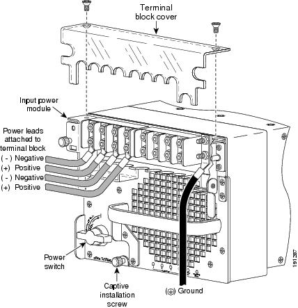
Note![]() If you are not going to remove the IPM, skip steps 7 and 8 and go to step 9.
If you are not going to remove the IPM, skip steps 7 and 8 and go to step 9.
Step 7![]() Loosen the IPM captive installation screws on the power supply. See Figure 1-41.
Loosen the IPM captive installation screws on the power supply. See Figure 1-41.
Step 8![]() Lift up on both IPM latches and remove the IPM. See Figure 1-43Figure 1-43.
Lift up on both IPM latches and remove the IPM. See Figure 1-43Figure 1-43.
Figure 1-43 Removing the IPM Module
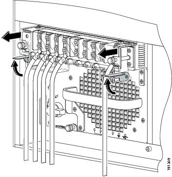
Step 9![]() Loosen the captive installation screw on the power supply (Figure 1-41).
Loosen the captive installation screw on the power supply (Figure 1-41).
Step 10![]() Grasp the power supply handle with one hand and slide the power supply part of the way out of the chassis. Place your other hand underneath the power supply, as shown in Figure 1-44 (without IPM) and in Figure 1-45 (with IPM),Figure 1-7 and slide the power supply completely out of the chassis.
Grasp the power supply handle with one hand and slide the power supply part of the way out of the chassis. Place your other hand underneath the power supply, as shown in Figure 1-44 (without IPM) and in Figure 1-45 (with IPM),Figure 1-7 and slide the power supply completely out of the chassis.
Note![]() If the power supply bay is to remain empty, install a blank power supply filler plate (Cisco part number 700-03104-01) over the opening, and secure it with the captive installation screws.
If the power supply bay is to remain empty, install a blank power supply filler plate (Cisco part number 700-03104-01) over the opening, and secure it with the captive installation screws.
Figure 1-44 Handling a DC-Input Power Supply without IPM

Figure 1-45 Handling a DC-Input Power Supply with IPM
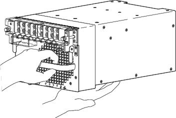
Installing a 6000 W DC-Input Power Supply
Note![]() With the PWR-6000-DC power supply, you have the option of installing an Input Power Module (IPM) (previously removed) with the DC-input wires and the ground wires still connected. You can then install your power supply and insert the fully-wired IPM. Read through this procedure carefully before installing your power supply.
With the PWR-6000-DC power supply, you have the option of installing an Input Power Module (IPM) (previously removed) with the DC-input wires and the ground wires still connected. You can then install your power supply and insert the fully-wired IPM. Read through this procedure carefully before installing your power supply.
Warning![]() Before performing any of the following procedures, ensure that power is removed from the DC circuits. To ensure that all power is removed, locate the circuit breakers or fuses on the DC power lines that service the DC circuits. Turn OFF the DC power line circuit breakers and remove the DC power line fuses. Statement 322
Before performing any of the following procedures, ensure that power is removed from the DC circuits. To ensure that all power is removed, locate the circuit breakers or fuses on the DC power lines that service the DC circuits. Turn OFF the DC power line circuit breakers and remove the DC power line fuses. Statement 322
Note![]() For proper 6000W DC-input redundant power configuration, all input wires (two pairs for 2800W DC-input, three pairs for 4500W DC-input, and four pairs for 6000W DC-input) for one 6000W DC-input power supply must come from the same battery system (A feed); all input wires (two pairs for 2800W DC-input, three pairs for 4500W DC-input, and four pairs for 6000W DC-input) for the other 6000W DC-input power supply must come from another battery system (B feed).
For proper 6000W DC-input redundant power configuration, all input wires (two pairs for 2800W DC-input, three pairs for 4500W DC-input, and four pairs for 6000W DC-input) for one 6000W DC-input power supply must come from the same battery system (A feed); all input wires (two pairs for 2800W DC-input, three pairs for 4500W DC-input, and four pairs for 6000W DC-input) for the other 6000W DC-input power supply must come from another battery system (B feed).
Note![]() For multiple DC input power supply, each DC input must be protected by dedicated circuit breaker or fuse. The circuit breaker or fuse should be sized according to the power supply input rating and local or national electrical code requirements.
For multiple DC input power supply, each DC input must be protected by dedicated circuit breaker or fuse. The circuit breaker or fuse should be sized according to the power supply input rating and local or national electrical code requirements.
Warning![]() When installing or replacing the unit, the ground connection must always be made first and disconnected last. Statement 1046
When installing or replacing the unit, the ground connection must always be made first and disconnected last. Statement 1046
Note![]() The 6000 W DC-input power supply provides power of 2800 W, 4500 W, or 6000 W. Select 2800 W by wiring any two positive (+)/negative (-) terminal pairs in any sequence. Select 4500 W by wiring any three positive (+)/negative (-) terminal pairs in any sequence. Select 6000 W by wiring all four positive (+)/negative (-) terminal pairs. The Cisco IOS software detects the wired inputs and sets the proper system power.
The 6000 W DC-input power supply provides power of 2800 W, 4500 W, or 6000 W. Select 2800 W by wiring any two positive (+)/negative (-) terminal pairs in any sequence. Select 4500 W by wiring any three positive (+)/negative (-) terminal pairs in any sequence. Select 6000 W by wiring all four positive (+)/negative (-) terminal pairs. The Cisco IOS software detects the wired inputs and sets the proper system power.
Note![]() The 6000 W DC-input power supply ground provides the system ground connection when the PWR-6000-DC power supply is installed in a Catalyst 6500 series chassis. Install the ground as described in this procedure.
The 6000 W DC-input power supply ground provides the system ground connection when the PWR-6000-DC power supply is installed in a Catalyst 6500 series chassis. Install the ground as described in this procedure.
Note![]() For redundant power supplies, you must connect the 6000 W DC-input power supply ground for both power supplies.
For redundant power supplies, you must connect the 6000 W DC-input power supply ground for both power supplies.
Note![]() You should allow a minimum of 2.5 to 3 inches (63.5 mm to 76.2 mm) of space between the side of the power supply and any obstructions (such as the side of an enclosed equipment rack). This space is needed to install and secure the DC-input power cables correctly. Incorrectly routing the DC-input power cables can cause airflow blockage into the power supply and inadequate strain relief in the cables. The exact amount of space required depends upon the gauge and flexibility of the DC-input power cables you are using.
You should allow a minimum of 2.5 to 3 inches (63.5 mm to 76.2 mm) of space between the side of the power supply and any obstructions (such as the side of an enclosed equipment rack). This space is needed to install and secure the DC-input power cables correctly. Incorrectly routing the DC-input power cables can cause airflow blockage into the power supply and inadequate strain relief in the cables. The exact amount of space required depends upon the gauge and flexibility of the DC-input power cables you are using.
To install a 6000 W DC-input power supply, follow these steps:
Step 1![]() Verify that power is off to the DC circuit that is connected to the power supply you are installing. Place appropriate safety flag and lockout devices at power switch handle to avoid any circuit inputs from becoming energized.
Verify that power is off to the DC circuit that is connected to the power supply you are installing. Place appropriate safety flag and lockout devices at power switch handle to avoid any circuit inputs from becoming energized.
Step 2![]() Grasp the power supply handle with one hand, and place your other hand underneath the power supply. Slide the power supply into the power supply bay. Make sure that the power supply is fully seated in the bay (Figure 1-46).
Grasp the power supply handle with one hand, and place your other hand underneath the power supply. Slide the power supply into the power supply bay. Make sure that the power supply is fully seated in the bay (Figure 1-46).
Figure 1-46 Handling a DC-Input Power Supply
Step 3![]() Tighten the power supply captive installation screw (see Figure 1-47).
Tighten the power supply captive installation screw (see Figure 1-47).
Figure 1-47 6000 W DC-Input Power Supply Front Panel
|
|
|
||
|
|
|
||
|
|
|
||
|
|
|
||
|
|
|
Warning![]() Power supply captive installation screws must be tight to ensure protective grounding continuity. Statement 289
Power supply captive installation screws must be tight to ensure protective grounding continuity. Statement 289
Note![]() With the PWR-6000-DC power supply, you have the option of installing an Input Power Module (IPM) (previously removed) with the DC-input wires and the ground wires still connected. You can then install your power supply and insert the fully-wired IPM. If you are going to install an IPM with DC-input wires and ground wires still connected, skip steps 4 through 12 and go directly to step 13.
With the PWR-6000-DC power supply, you have the option of installing an Input Power Module (IPM) (previously removed) with the DC-input wires and the ground wires still connected. You can then install your power supply and insert the fully-wired IPM. If you are going to install an IPM with DC-input wires and ground wires still connected, skip steps 4 through 12 and go directly to step 13.
Step 4![]() Remove the two A4 screws securing the outer terminal block cover, and remove the cover from the power supply (Figure 1-47).
Remove the two A4 screws securing the outer terminal block cover, and remove the cover from the power supply (Figure 1-47).
Step 5![]() Attach the appropriate lugs to the DC-input wires and ground wire. The wires should be sized according to local and national installation requirements. Use only copper wire.
Attach the appropriate lugs to the DC-input wires and ground wire. The wires should be sized according to local and national installation requirements. Use only copper wire.
Note![]() 6000 W power supplies ship with AWG #4 lugs with 45-degree angled, 2-hole compression lug for both power and ground wiring. Additional lugs for different wire size should be purchased separately.
6000 W power supplies ship with AWG #4 lugs with 45-degree angled, 2-hole compression lug for both power and ground wiring. Additional lugs for different wire size should be purchased separately.
Note![]() The power supply terminal block lug opening width is 0.62 inch (15.8 mm). The terminal posts are centered 0.625 inches (15.88 mm) apart and are 1/4-20 threaded. We recommend that you use an appropriately sized industry standard 45 degree angled, 2-hole, standard barrel compression lug for both power and ground lugs (for example, on AWG #4 wires, Panduit part number LCC4-14AWH-L or equivalent). The power supply ground studs, located beside the terminal block.
The power supply terminal block lug opening width is 0.62 inch (15.8 mm). The terminal posts are centered 0.625 inches (15.88 mm) apart and are 1/4-20 threaded. We recommend that you use an appropriately sized industry standard 45 degree angled, 2-hole, standard barrel compression lug for both power and ground lugs (for example, on AWG #4 wires, Panduit part number LCC4-14AWH-L or equivalent). The power supply ground studs, located beside the terminal block.
Note![]() For 6000 W power supplies, use fine-stranded copper conductors rated for 90-degrees Celsius for North American installations.
For 6000 W power supplies, use fine-stranded copper conductors rated for 90-degrees Celsius for North American installations.
Note![]() The 6000 W DC-input power supply provides voltages of 2800 W, 4500 W, or 6000 W. Select 2800 W by wiring any two positive (+)/negative (-) terminal pairs in any sequence. Select 4500 W by wiring any three positive (+)/negative (-) terminal pairs in any sequence. Select 6000 W by wiring all four terminals. The Cisco IOS software detects the wired inputs and sets the proper system power.
The 6000 W DC-input power supply provides voltages of 2800 W, 4500 W, or 6000 W. Select 2800 W by wiring any two positive (+)/negative (-) terminal pairs in any sequence. Select 4500 W by wiring any three positive (+)/negative (-) terminal pairs in any sequence. Select 6000 W by wiring all four terminals. The Cisco IOS software detects the wired inputs and sets the proper system power.
Note![]() If you are wiring for 2800 W for a single power supply, proceed to Step 7; if you are wiring 2800 W for a redundant power supply, proceed to Step 7 and then Step 10. In either case, proceed to step 14 upon completion.
If you are wiring for 2800 W for a single power supply, proceed to Step 7; if you are wiring 2800 W for a redundant power supply, proceed to Step 7 and then Step 10. In either case, proceed to step 14 upon completion.
Note![]() If you are wiring for 4500 W for a single power supply, proceed to Step 8; if you are wiring 4500 W for a redundant power supply, proceed to Step 8 and then Step 11. In either case, proceed to step 14 upon completion.
If you are wiring for 4500 W for a single power supply, proceed to Step 8; if you are wiring 4500 W for a redundant power supply, proceed to Step 8 and then Step 11. In either case, proceed to step 14 upon completion.
Note![]() If you are wiring for 6000 W for a single power supply, proceed to Step 9; if you are wiring 6000 W for a redundant power supply, proceed to Step 9 and then Step 12. In either case, proceed to step 14 upon completion.
If you are wiring for 6000 W for a single power supply, proceed to Step 9; if you are wiring 6000 W for a redundant power supply, proceed to Step 9 and then Step 12. In either case, proceed to step 14 upon completion.
Step 6![]() Wire for 2800 W (left side of power supply bay) as follows:
Wire for 2800 W (left side of power supply bay) as follows:
a.![]() From the left side of the power supply, connect the ground wire to the ground (Figure 1-48).
From the left side of the power supply, connect the ground wire to the ground (Figure 1-48).
Figure 1-48 DC-Input Wire Connections for 2700-W DC-Input Power Supply for Left Side of Power Bay
b.![]() From the left side of the power supply, connect each of the DC-input wires to the terminal block (Figure 1-48 and Figure 1-49) in this order:
From the left side of the power supply, connect each of the DC-input wires to the terminal block (Figure 1-48 and Figure 1-49) in this order:
Note![]() When you tighten the terminal nuts, make sure they are snug. Do not over tighten them. Recommended torque strength is 20 inch-pounds. Over tightening the terminal nuts can break the terminal block (Maximum torque: 36 inch-pounds).
When you tighten the terminal nuts, make sure they are snug. Do not over tighten them. Recommended torque strength is 20 inch-pounds. Over tightening the terminal nuts can break the terminal block (Maximum torque: 36 inch-pounds).
Step 7![]() Wire for 4500 W (left side of power supply bay) as follows:
Wire for 4500 W (left side of power supply bay) as follows:
a.![]() From the left side of the power supply, connect the ground wire to the ground (see Figure 1-49).
From the left side of the power supply, connect the ground wire to the ground (see Figure 1-49).
Figure 1-49 DC-Input Wire Connections for 4000-W DC-Input Power Supply for Left Side of Power Bay
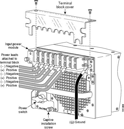
b.![]() From the left side of the power supply, connect each of the DC-input wires to the terminal block in this order (see Figure 1-47 and Figure 1-49):
From the left side of the power supply, connect each of the DC-input wires to the terminal block in this order (see Figure 1-47 and Figure 1-49):
Note![]() When you tighten the terminal nuts, make sure they are snug. Do not over tighten them. Recommended torque strength is 20 inch-pounds. Over tightening the terminal nuts can break the terminal block (Maximum torque: 36 inch-pounds).
When you tighten the terminal nuts, make sure they are snug. Do not over tighten them. Recommended torque strength is 20 inch-pounds. Over tightening the terminal nuts can break the terminal block (Maximum torque: 36 inch-pounds).
Step 8![]() Wire for 6000 W (left side of power supply bay) as follows:
Wire for 6000 W (left side of power supply bay) as follows:
a.![]() From the left side of the power supply, connect the ground wire to the ground (see Figure 1-50).
From the left side of the power supply, connect the ground wire to the ground (see Figure 1-50).
Figure 1-50 DC-Input Wire Connections for 6000-W DC-Input Power Supply for Left Side of Power Bay

b.![]() From the left side of the power supply, connect each of the DC-input wires to the terminal block in this order (see Figure 1-47 and Figure 1-50):
From the left side of the power supply, connect each of the DC-input wires to the terminal block in this order (see Figure 1-47 and Figure 1-50):
Note![]() When you tighten the terminal nuts, make sure they are snug. Do not over tighten them. Recommended torque strength is 20 inch-pounds. Over tightening the terminal nuts can break the terminal block (Maximum torque: 36 inch-pounds).
When you tighten the terminal nuts, make sure they are snug. Do not over tighten them. Recommended torque strength is 20 inch-pounds. Over tightening the terminal nuts can break the terminal block (Maximum torque: 36 inch-pounds).
Step 9![]() Wire for 2800 W (right side of power supply bay) as follows:
Wire for 2800 W (right side of power supply bay) as follows:
a.![]() From the right side of the power supply, connect the ground wire to the ground (see Figure 1-51).
From the right side of the power supply, connect the ground wire to the ground (see Figure 1-51).
Figure 1-51 DC-Input Wire Connections for 2700-W DC-Input Power Supply, Right Side of Power Bay
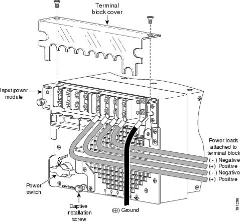
b.![]() From the right side of the power supply, connect the DC-input wires to the terminal block (see Figure 1-47 and Figure 1-51) in this order:
From the right side of the power supply, connect the DC-input wires to the terminal block (see Figure 1-47 and Figure 1-51) in this order:
Note![]() When you tighten the terminal nuts, make sure they are snug. Do not over tighten them. Recommended torque strength is 20 inch-pounds. Over tightening the terminal nuts can break the terminal block (Maximum torque: 36 inch-pounds).
When you tighten the terminal nuts, make sure they are snug. Do not over tighten them. Recommended torque strength is 20 inch-pounds. Over tightening the terminal nuts can break the terminal block (Maximum torque: 36 inch-pounds).
Note![]() For proper 2800W DC-input redundant power configuration, both pairs of input wires for one 6000W DC-input power supply must come from the same battery system (A feed); both pairs of input wires for the other 6000W DC-input power supply must come from another battery system (B feed).
For proper 2800W DC-input redundant power configuration, both pairs of input wires for one 6000W DC-input power supply must come from the same battery system (A feed); both pairs of input wires for the other 6000W DC-input power supply must come from another battery system (B feed).
Note![]() For multiple DC input power supply, each DC input must be protected by dedicated circuit breaker or fuse. The circuit breaker or fuse should be sized according to the power supply input rating and local or national electrical code requirements.
For multiple DC input power supply, each DC input must be protected by dedicated circuit breaker or fuse. The circuit breaker or fuse should be sized according to the power supply input rating and local or national electrical code requirements.
Step 10![]() Wire for 4500 W (right side of power supply bay) as follows:
Wire for 4500 W (right side of power supply bay) as follows:
a.![]() From the right side of the power supply, connect the ground wire to the ground (see Figure 1-52).
From the right side of the power supply, connect the ground wire to the ground (see Figure 1-52).
Figure 1-52 DC-Input Wire Connections for 4000-W DC-Input Power Supply, Right Side of Power Bay

b.![]() \From the right side of the power supply, connect each of the DC-input wires to the right power supply terminal block (see Figure 1-47 and Figure 1-52) in this order:
\From the right side of the power supply, connect each of the DC-input wires to the right power supply terminal block (see Figure 1-47 and Figure 1-52) in this order:
Note![]() When you tighten the terminal nuts, make sure they are snug. Do not over tighten them. Recommended torque strength is 20 inch-pounds. Over tightening the terminal nuts can break the terminal block (Maximum torque: 36 inch-pounds).
When you tighten the terminal nuts, make sure they are snug. Do not over tighten them. Recommended torque strength is 20 inch-pounds. Over tightening the terminal nuts can break the terminal block (Maximum torque: 36 inch-pounds).
Note![]() For proper 4500W DC-input redundant power configuration, three pairs of input wires for one 6000W DC-input power supply must come from the same battery system (A feed); three pairs of input wires for the other 6000W DC-input power supply must come from another battery system (B feed).
For proper 4500W DC-input redundant power configuration, three pairs of input wires for one 6000W DC-input power supply must come from the same battery system (A feed); three pairs of input wires for the other 6000W DC-input power supply must come from another battery system (B feed).
Note![]() For multiple DC input power supply, each DC input must be protected by dedicated circuit breaker or fuse. The circuit breaker or fuse should be sized according to the power supply input rating and local or national electrical code requirements.
For multiple DC input power supply, each DC input must be protected by dedicated circuit breaker or fuse. The circuit breaker or fuse should be sized according to the power supply input rating and local or national electrical code requirements.
Step 11![]() Wire for 6000 W (right side of power supply bay) as follows:
Wire for 6000 W (right side of power supply bay) as follows:
a.![]() From the right side of the power supply, connect the ground wire to the ground (see Figure 1-53).
From the right side of the power supply, connect the ground wire to the ground (see Figure 1-53).
Figure 1-53 DC-Input Wire Connections for 6000-W DC-Input Power Supply for Right Side of Power Bay

b.![]() From the right side of the power supply, connect each of the DC-input wires to the terminal block (Figure 1-47 and Figure 1-53) in this order:
From the right side of the power supply, connect each of the DC-input wires to the terminal block (Figure 1-47 and Figure 1-53) in this order:
Note![]() When you tighten the terminal nuts, make sure they are snug. Do not over tighten them. Recommended torque strength is 20 inch-pounds. Over tightening the terminal nuts can break the terminal block (Maximum torque: 36 inch-pounds).
When you tighten the terminal nuts, make sure they are snug. Do not over tighten them. Recommended torque strength is 20 inch-pounds. Over tightening the terminal nuts can break the terminal block (Maximum torque: 36 inch-pounds).
Note![]() For proper 6000W DC-input redundant power configuration, all four pairs of input wires for one 6000W DC-input power supply must come from the same battery system (A feed); all four pairs of input wires for the other 4000W DC-input power supply must come from another battery system (B feed).
For proper 6000W DC-input redundant power configuration, all four pairs of input wires for one 6000W DC-input power supply must come from the same battery system (A feed); all four pairs of input wires for the other 4000W DC-input power supply must come from another battery system (B feed).
Note![]() For multiple DC input power supply, each DC input must be protected by dedicated circuit breaker or fuse. The circuit breaker or fuse should be sized according to the power supply input rating and local or national electrical code requirements.
For multiple DC input power supply, each DC input must be protected by dedicated circuit breaker or fuse. The circuit breaker or fuse should be sized according to the power supply input rating and local or national electrical code requirements.
Warning![]() When installing the unit, always make the ground connection first and disconnect it last. Statement 42
When installing the unit, always make the ground connection first and disconnect it last. Statement 42
Step 12![]() If you are installing a previously-wired IPM, insert the IPM firmly into the power supply and tighten the IPM captive screws. (See Figure 1-54.)
If you are installing a previously-wired IPM, insert the IPM firmly into the power supply and tighten the IPM captive screws. (See Figure 1-54.)
Figure 1-54 Inserting Previously-Wired IPM (2700W DC-input shown)
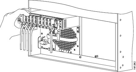
Step 13![]() After confirming all installation steps are correctly completed, safety flags and lockout devices can be removed, and the input circuits to the supplies can be energized.
After confirming all installation steps are correctly completed, safety flags and lockout devices can be removed, and the input circuits to the supplies can be energized.
Step 14![]() Use the power switch to turn the power supply on.
Use the power switch to turn the power supply on.
Step 15![]() Verify power supply operation by checking that the power supply front panel LEDs are in the following states:
Verify power supply operation by checking that the power supply front panel LEDs are in the following states:
Removing and Installing PEMs
This section describes how to remove and install the Power Entry Modules (PEMs) for the Catalyst 6503 and Catalyst 6503-E switches. There are three PEM models:
Note![]() The PEM is used on the Catalyst 6503 and Catalyst 6503-E switches only.
The PEM is used on the Catalyst 6503 and Catalyst 6503-E switches only.
The PEM provides an input power connection on the front of the chassis to connect the site power source to the power supply. In addition to providing an input power connection, the PEM also has an illuminated power switch (AC-input only), current protection, surge and EMI suppression, and filtering functions.
See Figure 1-55 for the location of the PEM; see Figure 1-56 for the location of the power supplies. The PEM on the left (PEM 1) connects the site power source to power supply 1; the PEM on the right (PEM 2) connects the site power source to power supply 2.
Figure 1-55 Catalyst 6503—PEM Location
Figure 1-56 Catalyst 6503 Switch—Power Supply Location
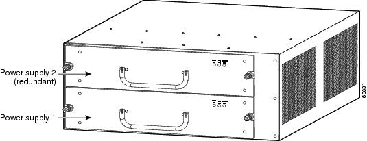
Required Tools
Use a flat-blade or number 2 Phillips-head screwdriver to perform these procedures. Additionally, wire cutters may be necessary to cut cable tie wraps.
Removing the AC-Input PEM
To remove an AC-input PEM, follow these steps:
Step 1![]() Turn the power switch to the off (0) position on the PEM that you are removing. (See Figure 1-55.)
Turn the power switch to the off (0) position on the PEM that you are removing. (See Figure 1-55.)
Step 2![]() Disconnect the power cord from the power source. Do not touch the metal prongs on the power cord when it is still connected to the PEM.
Disconnect the power cord from the power source. Do not touch the metal prongs on the power cord when it is still connected to the PEM.
Step 3![]() Remove the power cord from the power connection on the PEM. Do not touch the metal prongs embedded in the PEM.
Remove the power cord from the power connection on the PEM. Do not touch the metal prongs embedded in the PEM.
Step 4![]() Loosen the two captive installation screws. (See Figure 1-57.)
Loosen the two captive installation screws. (See Figure 1-57.)
Step 5![]() Grasp the PEM with one hand, and slide it part of the way out of the chassis. Place your other hand underneath the PEM, as shown in Figure 1-58,Figure 1-7 and slide it completely out of the chassis.
Grasp the PEM with one hand, and slide it part of the way out of the chassis. Place your other hand underneath the PEM, as shown in Figure 1-58,Figure 1-7 and slide it completely out of the chassis.
Step 6![]() If the PEM bay is to remain empty, install a blank PEM filler plate (Cisco part number 800-16719-01) over the opening, and secure it with the captive installation screws.
If the PEM bay is to remain empty, install a blank PEM filler plate (Cisco part number 800-16719-01) over the opening, and secure it with the captive installation screws.
Figure 1-57 AC-Input PEM (PEM-20A-AC+ Shown)
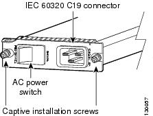
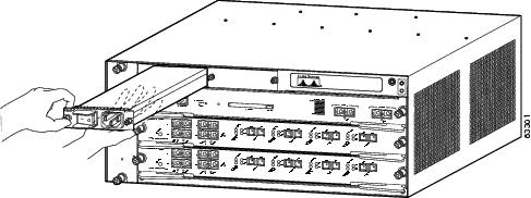
Installing the AC-Input PEM
To install an AC-input PEM, follow these steps:
Step 1![]() Ensure that the system (earth) ground connection has been made.
Ensure that the system (earth) ground connection has been made.
For ground connection instructions, see the “Establishing the System Ground” section.
Step 2![]() If necessary, remove the blank PEM filler plate (Cisco part number 800-16719-01) from the chassis PEM bay opening by loosening the captive installation screws. Retain the blank PEM filler plate for future use.
If necessary, remove the blank PEM filler plate (Cisco part number 800-16719-01) from the chassis PEM bay opening by loosening the captive installation screws. Retain the blank PEM filler plate for future use.
Step 3![]() Grasp the PEM with one hand. Place your other hand underneath the PEM, as shown in Figure 1-58Figure 1-7. Slide the PEM into the PEM bay. Make sure that the PEM is fully seated in the bay.
Grasp the PEM with one hand. Place your other hand underneath the PEM, as shown in Figure 1-58Figure 1-7. Slide the PEM into the PEM bay. Make sure that the PEM is fully seated in the bay.
Step 4![]() Tighten the PEM captive installation screws. (See Figure 1-57.)
Tighten the PEM captive installation screws. (See Figure 1-57.)
Step 5![]() Plug the power cord into the PEM.
Plug the power cord into the PEM.
Note![]() See Appendix A for a list of supported AC power cords.
See Appendix A for a list of supported AC power cords.
Step 6![]() Connect the other end of the power cord to an AC-input power source.
Connect the other end of the power cord to an AC-input power source.
Step 7![]() Turn the power switch to the on (|) position on the PEM.
Turn the power switch to the on (|) position on the PEM.
Removing the DC-Input PEM
Warning![]() Before performing any of the following procedures, ensure that power is removed from the DC circuit. Statement 1003
Before performing any of the following procedures, ensure that power is removed from the DC circuit. Statement 1003
Warning![]() Hazardous voltage or energy is present on the backplane when the system is operating. Use caution when servicing. Statement 1034
Hazardous voltage or energy is present on the backplane when the system is operating. Use caution when servicing. Statement 1034
Warning![]() When installing or replacing the unit, the ground connection must always be made first and disconnected last. Statement 1046
When installing or replacing the unit, the ground connection must always be made first and disconnected last. Statement 1046
To remove a DC-input PEM, follow these steps:
Step 1![]() Verify that power is off to the DC circuit for the PEM that you are removing. As an added precaution, place the appropriate safety flag and lockout devices at the source power circuit breaker, or place a piece of adhesive tape over the circuit breaker handle to prevent accidental power restoration while you are working on the circuit.
Verify that power is off to the DC circuit for the PEM that you are removing. As an added precaution, place the appropriate safety flag and lockout devices at the source power circuit breaker, or place a piece of adhesive tape over the circuit breaker handle to prevent accidental power restoration while you are working on the circuit.
Step 2![]() Loosen the two captive installation screws on the PEM. (See Figure 1-59.)
Loosen the two captive installation screws on the PEM. (See Figure 1-59.)
Step 3![]() Slide the PEM part way out of the chassis so that you have access to the PEM terminal block screws. (See Figure 1-60.)
Slide the PEM part way out of the chassis so that you have access to the PEM terminal block screws. (See Figure 1-60.)
Step 4![]() Disconnect the DC-input wires from the PEM terminal block in this order:
Disconnect the DC-input wires from the PEM terminal block in this order:
Note![]() It is not necessary to disconnect the system ground connection.
It is not necessary to disconnect the system ground connection.
Step 5![]() Grasp the PEM with one hand, and place your other hand underneath the PEM, as shown in Figure 1-61, and slide the PEM completely out of the chassis. Set the PEM aside.
Grasp the PEM with one hand, and place your other hand underneath the PEM, as shown in Figure 1-61, and slide the PEM completely out of the chassis. Set the PEM aside.
Step 6![]() If the PEM bay is to remain empty, install a blank PEM filler plate (Cisco part number 800-16719-01) over the opening, and secure it in place with the two captive installation screws.
If the PEM bay is to remain empty, install a blank PEM filler plate (Cisco part number 800-16719-01) over the opening, and secure it in place with the two captive installation screws.
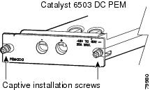
Figure 1-60 DC-Input PEM Terminal Block Screws
Figure 1-61 Handling a DC-Input PEM

Installing the DC-Input PEM
Warning![]() Before performing any of the following procedures, ensure that power is removed from the DC circuit. Statement 1003
Before performing any of the following procedures, ensure that power is removed from the DC circuit. Statement 1003
Warning![]() When installing or replacing the unit, the ground connection must always be made first and disconnected last. Statement 1046
When installing or replacing the unit, the ground connection must always be made first and disconnected last. Statement 1046
To install a DC-input PEM, follow these steps:
Step 1![]() Ensure that the system (earth) ground connection has been made. For ground connection installation instructions, see the “Establishing the System Ground” section.
Ensure that the system (earth) ground connection has been made. For ground connection installation instructions, see the “Establishing the System Ground” section.
Step 2![]() Verify that power is off to the DC circuit for the PEM that you are installing. As an added precaution, place the appropriate safety flag and lockout devices at the source power circuit breaker, or place a piece of adhesive tape over the circuit breaker handle to prevent accidental power restoration while you are working on the circuit.
Verify that power is off to the DC circuit for the PEM that you are installing. As an added precaution, place the appropriate safety flag and lockout devices at the source power circuit breaker, or place a piece of adhesive tape over the circuit breaker handle to prevent accidental power restoration while you are working on the circuit.
Step 3![]() Install the PEM partially into the chassis so that you still have access to the PEM terminal block screws. (See Figure 1-62.)
Install the PEM partially into the chassis so that you still have access to the PEM terminal block screws. (See Figure 1-62.)
Figure 1-62 DC-Input PEM Terminal Block Screws
Step 4![]() Connect the DC-input wires to the terminal block in this order:
Connect the DC-input wires to the terminal block in this order:
Step 5![]() After ensuring that all wire connections are secure, install the PEM in the bay.
After ensuring that all wire connections are secure, install the PEM in the bay.
Step 6![]() Tighten the power supply captive installation screws. (See Figure 1-63.)
Tighten the power supply captive installation screws. (See Figure 1-63.)
Step 7![]() Remove the safety flag, lockout devices, or tape from the circuit breaker switch handle, and restore power by moving the circuit breaker switch handle to the on (|) position.
Remove the safety flag, lockout devices, or tape from the circuit breaker switch handle, and restore power by moving the circuit breaker switch handle to the on (|) position.
Step 8![]() Verify the power supply operation by ensuring that the power supply front panel LEDs are in the following states:
Verify the power supply operation by ensuring that the power supply front panel LEDs are in the following states:
If the LEDs indicate a power problem, see the “Identifying Startup Problems” section.
Removing and Installing the Fan Tray
This section describes how to remove and install fan trays for the Catalyst 6500 series switches.
Note![]() If your Catalyst 6506, Catalyst 6509, or Catalyst 6509-NEB chassis is equipped with a Supervisor Engine 2 and you using the fan tray removal and replacement procedure to upgrade the chassis from a fan tray 1 (low-speed) to a fan tray 2 (high-speed), you must first check the chassis configuration using the hw-module fan-tray version 2 command to check for configuration problems, such as power supply compatibility and power sufficiency. If the system does not detect any configuration issues, a message is displayed saying that it is OK to change the fan trays. This command applies to Catalyst 6500 series switches that are configured with a Supervisor Engine 2 only. This command is not required in systems that are configured with either a Supervisor Engine 720 or a Supervisor Engine 32.
If your Catalyst 6506, Catalyst 6509, or Catalyst 6509-NEB chassis is equipped with a Supervisor Engine 2 and you using the fan tray removal and replacement procedure to upgrade the chassis from a fan tray 1 (low-speed) to a fan tray 2 (high-speed), you must first check the chassis configuration using the hw-module fan-tray version 2 command to check for configuration problems, such as power supply compatibility and power sufficiency. If the system does not detect any configuration issues, a message is displayed saying that it is OK to change the fan trays. This command applies to Catalyst 6500 series switches that are configured with a Supervisor Engine 2 only. This command is not required in systems that are configured with either a Supervisor Engine 720 or a Supervisor Engine 32.
Required Tools
You might need a flat-blade or number 2 Phillips-head screwdriver to loosen or tighten the captive installation screws on the fan tray.
Removing the Fan Tray
The fan Tray is designed to be removed and replaced while the system is operating without presenting an electrical hazard or damage to the system.
Warning![]() When removing the fan tray, keep your hands and fingers away from the spinning fan blades. Let the fan blades completely stop before you remove the fan tray. Statement 258
When removing the fan tray, keep your hands and fingers away from the spinning fan blades. Let the fan blades completely stop before you remove the fan tray. Statement 258
To remove the existing fan assembly, follow these steps:
Step 1![]() If you are upgrading your chassis from a fan tray 1 (low speed) to a fan tray 2 (high speed) and your chassis is equipped with a Supervisor Engine 2, you need to check that the current chassis configuration supports the fan tray upgrade. To do this, use the command hw-module fan-tray version 2 to check for configuration problems, such as power supply compatibility and power sufficiency.
If you are upgrading your chassis from a fan tray 1 (low speed) to a fan tray 2 (high speed) and your chassis is equipped with a Supervisor Engine 2, you need to check that the current chassis configuration supports the fan tray upgrade. To do this, use the command hw-module fan-tray version 2 to check for configuration problems, such as power supply compatibility and power sufficiency.
If the system does not detect any configuration issues, a message is displayed saying that it is OK to change the fan trays. If your chassis has either a Supervisor Engine 32 or a Supervisor Engine 720, skip this step and proceed to Step 2.
Step 2![]() Locate the fan assembly in the chassis as follows:
Locate the fan assembly in the chassis as follows:
- Catalyst 6503 and Catalyst 6503-E switches—The fan tray is located to the left of the module cage. (See Figure 1-64.)
- Catalyst 6504-E switch—The fan tray is located to the left of the module cage. (See Figure 1-65.)
- Catalyst 6506 and Catalyst 6506-E switches—The fan tray is located to the left of the module cage. (See Figure 1-66.)
- Catalyst 6509 and Catalyst 6509-E switches—The fan tray is located to the left of the module cage. (See Figure 1-67.)
- Catalyst 6509-NEB switch—The fan tray is located above the module cage. (See Figure 1-68.)
- Catalyst 6509-NEB-A and Catalyst 6509-V-E switches —On those switch chassis equipped with the optional cable management system, you must first loosen the two captive installation screws located at the top of the cable management system and fold the cable guide down to access the fan assembly. (See Figure 1-69.) See Figure 1-70 for the location of the two fan trays on the Catalyst 6509-NEB-A switch.
Note![]() Make sure there is adequate slack in the network interface cables to allow the cable guide to pivot down far enough to access the fan tray. If there is insufficient slack in the cables, the cable guide will not pivot far enough to give you access to the fan trays.
Make sure there is adequate slack in the network interface cables to allow the cable guide to pivot down far enough to access the fan tray. If there is insufficient slack in the cables, the cable guide will not pivot far enough to give you access to the fan trays.
- Catalyst 6513 switch—The fan tray is located to the left of the module cage. (See Figure 1-71.)
- Catalyst 6513-E switch—The fan tray is located to the left of the module cage. Access to the fan tray is from the rear of the chassis. (See Figure 1-72.)
Step 3![]() Loosen the two fan tray captive installation screws by turning them counterclockwise.
Loosen the two fan tray captive installation screws by turning them counterclockwise.
Step 4![]() Grasp the fan assembly with both hands, and pull it outward; rock it gently, if necessary, to unseat the fan assembly power connector from the backplane.
Grasp the fan assembly with both hands, and pull it outward; rock it gently, if necessary, to unseat the fan assembly power connector from the backplane.
Step 5![]() Pull the fan assembly clear of the chassis, and set it aside.
Pull the fan assembly clear of the chassis, and set it aside.
Figure 1-64 Fan Assembly: Catalyst 6503 and Catalyst 6503-E Switches
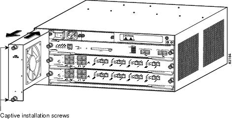
Figure 1-65 Fan Assembly: Catalyst 6504-E Switch
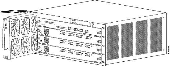
Figure 1-66 Fan Assembly: Catalyst 6506 and Catalyst 6506-E Switches
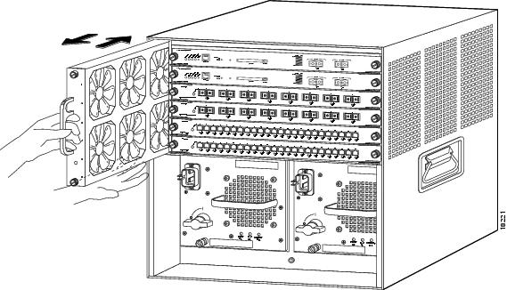
Figure 1-67 Fan Assembly: Catalyst 6509 and Catalyst 6509-E Switches
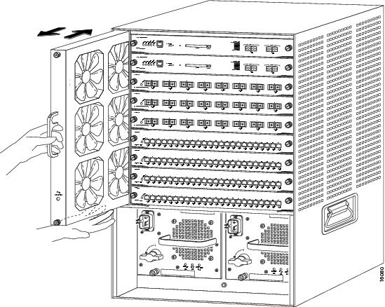
Figure 1-68 Fan Assembly: Catalyst 6509-NEB Switch
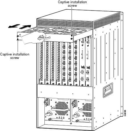
Figure 1-69 Accessing the Fan Trays on the Catalyst 6509-NEB-A and the Catalyst 6509-V-E Switches

Figure 1-70 Fan Assembly: Catalyst 6509-NEB-A and Catalyst 6509-V-E Switches
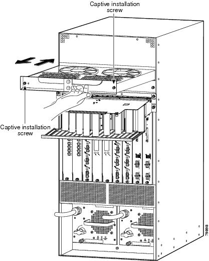
Figure 1-71 Fan Assembly: Catalyst 6513 Switch
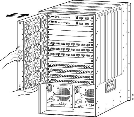
Figure 1-72 Fan Tray: Catalyst 6513-E Switch
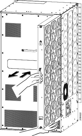
Installing the Fan Assembly
To install the new fan assembly, follow these steps:
Step 1![]() Hold the fan assembly with the fans facing to the right and the FAN STATUS LED at the bottom.
Hold the fan assembly with the fans facing to the right and the FAN STATUS LED at the bottom.
- See Figure 1-64 for the Catalyst 6503 and Catalyst 6503-E switches.
- See Figure 1-65 for the Catalyst 6504-E switch.
- See Figure 1-66 for the Catalyst 6506 and Catalyst 6506-E switches.
- See Figure 1-67 for the Catalyst 6509 and Catalyst 6509-E switches.
- See Figure 1-71 for the Catalyst 6513 switch.
- See Figure 1-72 for the Catalyst 6513-E switch
For the Catalyst 6509-NEB switch, hold the fan assembly with the fans facing down and the FAN STATUS LED on the left. (See Figure 1-68.) For the Catalyst 6509-NEB-A and the Catalyst 6509-V-E switches, hold the fan assembly so that the handle is at the top of the assembly. (See Figure 1-70.)
Step 2![]() Place the fan assembly into the front chassis cavity so that it rests on the chassis, and then lift the fan assembly up slightly, aligning the top and bottom chassis guides.
Place the fan assembly into the front chassis cavity so that it rests on the chassis, and then lift the fan assembly up slightly, aligning the top and bottom chassis guides.
Step 3![]() Push the fan assembly into the chassis until the power connector seats in the backplane and the captive installation screws make contact with the chassis.
Push the fan assembly into the chassis until the power connector seats in the backplane and the captive installation screws make contact with the chassis.
Step 4![]() Tighten the captive installation screws.
Tighten the captive installation screws.
Step 5![]() On the Catalyst 6509-NEB-A and the Catalyst 6509-V-E switches, fold the cable guide up, and tighten the two captive installation screws at the top of the chassis. (See Figure 1-69.)
On the Catalyst 6509-NEB-A and the Catalyst 6509-V-E switches, fold the cable guide up, and tighten the two captive installation screws at the top of the chassis. (See Figure 1-69.)
- A fully populated Catalyst 6509-V-E cable management system can be very heavy. As you pivot the cable guide back up after replacing the fan tray, you should gently rock the cable guide to allow the network interface cables to align themselves. This makes it easier for you to position the cable guide in front of the chassis so that the two captive installation screws can be engaged and tightened. Make sure that the network interface cables are not caught or pinched in the cable guide.
- After positioning and securing the Catalyst 6509-V-E cable guide, verify that the tab at the back of the cable guide front panel is still engaged in the slot on the back of the cable guide next to the chassis. If the tab has popped loose, you must reinstall the tab in the slot.
Checking the Installation
To verify that the new fan assembly is installed correctly, follow these steps:
Step 1![]() Listen for the fans; you should immediately hear them operating. If you do not hear them, ensure that the fan assembly is inserted completely in the chassis and that the faceplate is flush with the switch back panel.
Listen for the fans; you should immediately hear them operating. If you do not hear them, ensure that the fan assembly is inserted completely in the chassis and that the faceplate is flush with the switch back panel.
Step 2![]() Verify that the FAN STATUS LED is green. If the LED is red, one or more of the fans are faulty.
Verify that the FAN STATUS LED is green. If the LED is red, one or more of the fans are faulty.
Step 3![]() If after several attempts the fans do not operate or if you experience trouble with the installation (for instance, if the captive installation screws do not align with the chassis holes), contact a Cisco customer service representative for assistance.
If after several attempts the fans do not operate or if you experience trouble with the installation (for instance, if the captive installation screws do not align with the chassis holes), contact a Cisco customer service representative for assistance.
Installing the Air Filter Assembly on a Catalyst 6509-NEB-A Switch or a Catalyst 6509-V-E (Optional)
This section describes how to install the optional air filter assembly for the Catalyst 6509-NEB-A switch or the Catalyst 6509-V-E switch. The filter assembly is designed to prevent dust and other contaminants from being drawn into the switch chassis. It is not included with the chassis or bundle configurations because it is not needed in normal installation environments. We recommend that you use this assembly only in exceptionally dusty installation sites.
The necessary parts can be ordered as listed in Table 1-3 . The filter assembly installation requires that INTAKEPNL-09= be installed on the chassis. This intake panel can be identified by the two filter assembly support loops extending from the bottom front of the panel and the thumbscrews on the front left and right sides of the panel. (See Figure 1-74.)
|
|
|
|---|---|
To install the new filter assembly, follow these steps. If INTAKEPNL-09= is already installed, skip to Step 3.
Step 1![]() Remove the intake panel by unscrewing four thumbscrews. (See Figure 1-73.)
Remove the intake panel by unscrewing four thumbscrews. (See Figure 1-73.)
Figure 1-73 Removing the Intake Panel
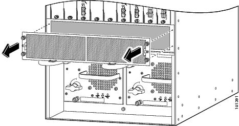
Step 2![]() Install the new intake panel by tightening four thumbscrews. (See Figure 1-74.)
Install the new intake panel by tightening four thumbscrews. (See Figure 1-74.)
Figure 1-74 Installing the New Intake Panel

|
|
|
||
|
|
|
Step 3![]() Remove the inner filter retainer from the filter cage assembly by depressing the thumb loops and carefully sliding filter retainer outwards. (See Figure 1-75.)
Remove the inner filter retainer from the filter cage assembly by depressing the thumb loops and carefully sliding filter retainer outwards. (See Figure 1-75.)
Figure 1-75 Removing the Inner Filter Retainer
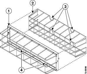
|
|
|
||
|
|
|
Step 4![]() Place the foam filter over the filter retainer. (See Figure 1-76.)
Place the foam filter over the filter retainer. (See Figure 1-76.)
Step 5![]() Slide the retainer and filter into the cage assembly.
Slide the retainer and filter into the cage assembly.
Figure 1-76 Placing the Foam Filter Over the Filter Retainer
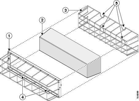
|
|
|
||
|
|
|
||
|
|
|
Step 6![]() Install the filter assembly with the tabs facing the floor, as follows:
Install the filter assembly with the tabs facing the floor, as follows:
a.![]() Fit the tabs (see Figure 1-76) on the bottom of the filter cage assembly into the lower support loops. (See Figure 1-74.)
Fit the tabs (see Figure 1-76) on the bottom of the filter cage assembly into the lower support loops. (See Figure 1-74.)
b.![]() Rotate the filter assembly towards the intake panel. (See Figure 1-77.)
Rotate the filter assembly towards the intake panel. (See Figure 1-77.)
c.![]() Tighten the two fastening screws.
Tighten the two fastening screws.
Figure 1-77 Installing the Filter Assembly
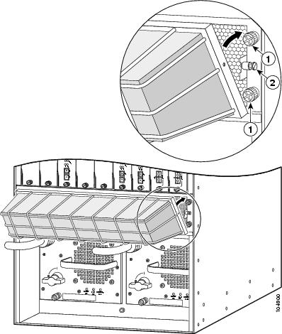
|
|
|
Step 7![]() After installing the optional air filter assembly, establish a schedule for visually checking the air filter for contamination. (See “Checking the Air Filter” section.)
After installing the optional air filter assembly, establish a schedule for visually checking the air filter for contamination. (See “Checking the Air Filter” section.)
Checking the Air Filter
Once you have installed the optional air filter assembly on the Catalyst 6509-NEB-A or Catalyst 6509-V-E switch chassis, you need to periodically check the air filter for damage and cleanliness. We recommend that you perform a visual inspection of the filter at least once a month, or more often in dusty environments. Replace the filter if appears clogged with dust, or you have detected an increase in the chassis internal operating temperature. Failure to periodically check the filter can result in restricted airflow through the filter leading to chassis overheating and degraded EMI performance.
Installing the Remote Power Cycling Feature Control Wires (Optional)
The remote power cycling feature allows you to power down and power up a switch chassis through the network rather than being physically present to turn the power supply power switch off and on. The remote power cycling feature is only available on the 8700 W AC-input power supply.
Several vendors make remote power cycling relay controller boxes that can be used to power cycle the Catalyst 6500 series switch chassis. Most of these relay controller boxes have the capability of controlling multiple power supplies. The relay controller boxes have a network interface that allows the user to remotely access the relay controller box and toggle a built-in relay. The built-in relay can be either a normally open (NO) type or a normally closed (NC) type of relay. We strongly recommend that you purchase a relay controller box that uses a NO relay. The relay controller box is installed near the switch chassis and is attached to the network. Two control wires extend from the relay controller box to a three-position terminal block located on the front of the 8700 W power supply. A signal from the relay controller box travels through the control wires to toggle the power supply on or off.
This section only describes how to install the remote power cycling feature control wires; relay controller box installation instructions should be provided by the maker of the relay controller box.
Note![]() The remote power cycling feature and this installation procedure are applicable only for the 8700 W AC-input power supply.
The remote power cycling feature and this installation procedure are applicable only for the 8700 W AC-input power supply.
Required Tools and Components
The following tools and components are required to perform this procedure:
We strongly recommend that you purchase a relay controller box that uses a NO (normally open) relay to control the remote power cycling.
Installing the Remote Power-Cycling Control Wires
To install the two control wires from the relay controller box to the 8700 W power supply, follow these steps:
Step 1![]() Remove the relay controller box from its shipping packaging.
Remove the relay controller box from its shipping packaging.
Step 2![]() Install the relay controller box following the installation documentation supplied with the product.
Install the relay controller box following the installation documentation supplied with the product.
Step 3![]() Measure and cut two pieces of 18 AWG control wire long enough to run between the relay controller box terminals and the terminal block on the 8700 W power supply.
Measure and cut two pieces of 18 AWG control wire long enough to run between the relay controller box terminals and the terminal block on the 8700 W power supply.
Step 4![]() Strip approximately 1/4-inch of insulation from each end of both control wires.
Strip approximately 1/4-inch of insulation from each end of both control wires.
Step 5![]() Connect the two control wires to the relay controller box terminals following the instruction documentation supplied with the relay controller box.
Connect the two control wires to the relay controller box terminals following the instruction documentation supplied with the relay controller box.
Step 6![]() Identify which pair of terminals on the power supply terminal block (either terminals 1 and 2 for a NO relay (recommended) or terminals 2 and 3 for a NC relay) where you need to connect the control wires. Using a small flat-blade screwdriver, depress the wire release mechanism for one of the terminals on the power supply terminal block and insert the bare wire into the terminal. (See Figure 1-78.) Remove the screwdriver to secure the wire. Gently tug on the wire to verify that it is secure in the terminal block.
Identify which pair of terminals on the power supply terminal block (either terminals 1 and 2 for a NO relay (recommended) or terminals 2 and 3 for a NC relay) where you need to connect the control wires. Using a small flat-blade screwdriver, depress the wire release mechanism for one of the terminals on the power supply terminal block and insert the bare wire into the terminal. (See Figure 1-78.) Remove the screwdriver to secure the wire. Gently tug on the wire to verify that it is secure in the terminal block.
Step 7![]() Repeat Step 6 for the second control wire.
Repeat Step 6 for the second control wire.
Figure 1-78 Installing the Relay Control Wires
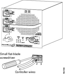
Step 8![]() Check the position of the relay controller switch located next to the terminal block.
Check the position of the relay controller switch located next to the terminal block.
The switch should be in the down, NO (normally open) position if the relay controller box uses a NO relay. This the default and the recommended position. If the relay controller box uses a NC relay, the relay controller switch should be in the up position.
You are now ready to install the ferrite bead on the control wires. Follow the installation instructions supplied in the package containing the ferrite bead or the installation procedure in the next section.
Installing the Ferrite Bead
The ferrite bead is a passive device that limits high-frequency interference on interface and control cables, and it is only required when you install the remote power-cycling feature that is supported only by the 8700 Watt power supply. The ferrite bead is installed on the two control wires that link the external relay controller box with the remote power-cycling terminal block on the 8700 W power supply. You do not need the ferrite bead for 8700 Watt power supply installations that do not include the remote power-cycling feature.
To install the ferrite bead on the remote power-cycling control wires, follow these steps:
Step 1![]() Remove the ferrite bead and the two plastic ties from the plastic bag.
Remove the ferrite bead and the two plastic ties from the plastic bag.
Step 2![]() Open the ferrite bead as shown in Figure 1-79, View A.
Open the ferrite bead as shown in Figure 1-79, View A.
Step 3![]() Place the two remote power-cycling control wires (18 AWG maximum) in the ferrite bead as shown in Figure 1-79, View B. Close the ferrite bead making sure that the two halves have completely snapped together and are secure.
Place the two remote power-cycling control wires (18 AWG maximum) in the ferrite bead as shown in Figure 1-79, View B. Close the ferrite bead making sure that the two halves have completely snapped together and are secure.
Step 4![]() Locate a point on the remote power-cycling control wires that leaves approximately 1 to 2 inches (2.5 to 5 cm) of exposed wire from the remote power cycling terminal block located on the front of the power supply. Wrap one of the 4-inch plastic ties around the remote power-cycling control wires at that point. Tighten the plastic tie so that it is snug against the control wires and cannot slide. See Figure 1-79, View C.
Locate a point on the remote power-cycling control wires that leaves approximately 1 to 2 inches (2.5 to 5 cm) of exposed wire from the remote power cycling terminal block located on the front of the power supply. Wrap one of the 4-inch plastic ties around the remote power-cycling control wires at that point. Tighten the plastic tie so that it is snug against the control wires and cannot slide. See Figure 1-79, View C.
Step 5![]() Slide the ferrite bead so that it is positioned just behind the first plastic tie wrap. Take the second plastic tie and wrap it around the control wires directly behind the ferrite bead and tighten it so that the ferrite bead cannot slide up or down the control wires. See Figure 1-79, View C.
Slide the ferrite bead so that it is positioned just behind the first plastic tie wrap. Take the second plastic tie and wrap it around the control wires directly behind the ferrite bead and tighten it so that the ferrite bead cannot slide up or down the control wires. See Figure 1-79, View C.
Step 6![]() To finish the procedure, trim the excess plastic strap from the two plastic tie wraps.
To finish the procedure, trim the excess plastic strap from the two plastic tie wraps.
Figure 1-79 Installing the Ferrite Bead

 Feedback