- Rack-Mounting Guidelines
- Unpacking the Switch
- Chassis Installation Kits and Cable Guides
- Installing a Catalyst6503 or Catalyst6503-E Switch Chassis
- Installing a Catalyst6504-E Switch Chassis
- Installing a Catalyst6506 or Catalyst 6506-E Switch Chassis
- Installing a Catalyst6509 or Catalyst6509-E Switch Chassis
- Installing a Catalyst6509-NEB or Catalyst6509-NEB-A Switch Chassis
- Installation Accessory Kits
- LBrackets and the Optional Cable Guide on the Catalyst6509-NEB Switch
- LBrackets on the Catalyst6509-NEB-A Switch Chassis
- Installing the 3 RU Rack-Mount Shelf Kit
- Rack-Mounting the Chassis
- Installing the Cable Management System (Catalyst6509-NEB-A Only)
- What is Next
- Optional Installation Kits
- Installing a Catalyst 6509-V-E Switch Chassis
- Installing a Catalyst 6513 or Catalyst 6513-E Switch Chassis
- Generic Installation Procedures
- Establishing the System Ground
Installing the Switch

Note![]() In this publication, the term Catalyst 6500 series refers only to the switch chassis listed in Chapter 1. The Catalyst 6000 series switches (Catalyst 6006 and Catalyst 6009 switches) are described in a separate publication, the Catalyst 6000 Series Switch Installation Guide.
In this publication, the term Catalyst 6500 series refers only to the switch chassis listed in Chapter 1. The Catalyst 6000 series switches (Catalyst 6006 and Catalyst 6009 switches) are described in a separate publication, the Catalyst 6000 Series Switch Installation Guide.
This chapter describes how to install a Catalyst 6500 series switch. The chapter is divided into sections that cover installing the different Catalyst 6500 series chassis. Pointers within the overall chassis installation procedures point to separate installation procedures that cover installing various components and assemblies. The process of installing the switch can be broken down into a series of tasks. These tasks are listed in Table 1-1 .
The chapter contains the following sections:
- Rack-Mounting Guidelines
- Unpacking the Switch
- Chassis Installation Kits and Cable Guides
- Installing a Catalyst 6503 or Catalyst 6503-E Switch Chassis
- Installing a Catalyst 6504-E Switch Chassis
- Installing a Catalyst 6506 or Catalyst 6506-E Switch Chassis
- Installing a Catalyst 6509 or Catalyst 6509-E Switch Chassis
- Installing a Catalyst 6509-NEB or Catalyst 6509-NEB-A Switch Chassis
- Installing a Catalyst 6509-V-E Switch Chassis
- Installing a Catalyst 6513 or Catalyst 6513-E Switch Chassis
- Generic Installation Procedures
- Establishing the System Ground
- Installing the Power Supplies in the Switch Chassis
- Attaching the Interface Cables
- Verifying Switch Chassis Installation

Warning![]() Class 1 laser product. Statement 1008
Class 1 laser product. Statement 1008
Warning![]() This unit is intended for installation in restricted access areas. A restricted access area can be accessed only through the use of a special tool, lock and key, or other means of security. Statement 1017
This unit is intended for installation in restricted access areas. A restricted access area can be accessed only through the use of a special tool, lock and key, or other means of security. Statement 1017
Warning![]() Only trained and qualified personnel should be allowed to install, replace, or service this equipment. Statement 1030
Only trained and qualified personnel should be allowed to install, replace, or service this equipment. Statement 1030
Warning![]() Ultimate disposal of this product should be handled according to all national laws and regulations. Statement 1040
Ultimate disposal of this product should be handled according to all national laws and regulations. Statement 1040
Warning![]() This equipment must be installed and maintained by service personnel as defined by AS/NZS 3260. Incorrectly connecting this equipment to a general-purpose outlet could be hazardous. The telecommunications lines must be disconnected 1) before unplugging the main power connector or 2) while the housing is open, or both. Statement 1043
This equipment must be installed and maintained by service personnel as defined by AS/NZS 3260. Incorrectly connecting this equipment to a general-purpose outlet could be hazardous. The telecommunications lines must be disconnected 1) before unplugging the main power connector or 2) while the housing is open, or both. Statement 1043
Warning![]() This product requires short-circuit (overcurrent) protection, to be provided as part of the building installation. Install only in accordance with national and local wiring regulations. Statement 1045
This product requires short-circuit (overcurrent) protection, to be provided as part of the building installation. Install only in accordance with national and local wiring regulations. Statement 1045
Warning![]() During this procedure, wear grounding wrist straps to avoid ESD damage to the card. Do not directly touch the backplane with your hand or any metal tool, or you could shock yourself. Statement 94
During this procedure, wear grounding wrist straps to avoid ESD damage to the card. Do not directly touch the backplane with your hand or any metal tool, or you could shock yourself. Statement 94
Note![]() If you are installing a freestanding (not rack-mounted) Catalyst 6509-NEB, Catalyst 6513, or Catalyst 6513-E switch, you must install the stabilizer bracket kit, which is included as part of the accessory kit for these two switch chassis.
If you are installing a freestanding (not rack-mounted) Catalyst 6509-NEB, Catalyst 6513, or Catalyst 6513-E switch, you must install the stabilizer bracket kit, which is included as part of the accessory kit for these two switch chassis.
Before starting the installation procedures in this chapter, see the “Site Preparation Checklist” section to verify that all site planning activities were completed.
Rack-Mounting Guidelines
The Catalyst 6500 series switches are designed to be installed in both open and enclosed racks. Before rack-mounting the switch, ensure that the equipment rack complies with the following guidelines:
- The width of the rack, measured between the two front-mounting strips or rails, must be 17.75 inches (45.09 cm).
- The depth of the rack, measured between the front- and rear-mounting strips, must be at least 19.25 inches (48.9 cm).
Note![]() All of the Catalyst 6500 series switch chassis are designed to install in standard 19-inch racks.
All of the Catalyst 6500 series switch chassis are designed to install in standard 19-inch racks.
- The rack must have sufficient vertical clearance to insert the chassis. These are the chassis heights:
|
|
|
||
|---|---|---|---|
Note![]() Chassis height is sometimes measured in rack units (RU or just U) where 1 RU or 1 U equals 1.75 in (44.45 mm). A typical server rack is 42 RU or 42 U in height.
Chassis height is sometimes measured in rack units (RU or just U) where 1 RU or 1 U equals 1.75 in (44.45 mm). A typical server rack is 42 RU or 42 U in height.

Note![]() To maintain proper air circulation through the Catalyst switch chassis, we recommend that you maintain a minimum 6-inch (15 cm) separation between a wall and the chassis air intake or a wall and the chassis air exhaust. You should also allow a minimum separation of 12 inches (30.5 cm) between the hot air exhaust on one chassis and the air intake on another chassis. Failure to maintain adequate air space can cause the chassis to overheat and the system to fail. On Catalyst switch chassis in which the airflow is from front to back, the chassis may be placed side-by-side.
To maintain proper air circulation through the Catalyst switch chassis, we recommend that you maintain a minimum 6-inch (15 cm) separation between a wall and the chassis air intake or a wall and the chassis air exhaust. You should also allow a minimum separation of 12 inches (30.5 cm) between the hot air exhaust on one chassis and the air intake on another chassis. Failure to maintain adequate air space can cause the chassis to overheat and the system to fail. On Catalyst switch chassis in which the airflow is from front to back, the chassis may be placed side-by-side.
Unpacking the Switch

Tip![]() Do not discard the shipping container when you unpack the switch. Flatten the shipping cartons and store them with the pallet. You will need these containers if you need to move or ship the switch in the future. Repacking instructions are provided in Appendix A, “Repacking the Switch.”
Do not discard the shipping container when you unpack the switch. Flatten the shipping cartons and store them with the pallet. You will need these containers if you need to move or ship the switch in the future. Repacking instructions are provided in Appendix A, “Repacking the Switch.”
To check the contents of the shipping container, perform the following:
- Check the contents of the accessory kit. Verify that you received all listed equipment, which should include the following:
–![]() Optional equipment that you ordered, such as network interface cables, transceivers, or special connectors
Optional equipment that you ordered, such as network interface cables, transceivers, or special connectors
- Check the modules in each slot. Ensure that the configuration matches the packing list and that all of the specified interfaces are included.
- Blank power supply covers are shipped as part of the accessory kit. They are not installed on the chassis.
Note![]() The Catalyst 6503-E and the Catalyst 6504-E switch chassis are shipped with a shipping bracket installed across the front of the chassis slots. Do not remove the shipping bracket at this time; remove the shipping bracket after you have installed the chassis in the rack.
The Catalyst 6503-E and the Catalyst 6504-E switch chassis are shipped with a shipping bracket installed across the front of the chassis slots. Do not remove the shipping bracket at this time; remove the shipping bracket after you have installed the chassis in the rack.
Chassis Installation Kits and Cable Guides
Each Catalyst 6500 series chassis ships with an accessory kit. Shipped as part of the accessory kit are chassis installation kits and cable guides. The chassis installation kits and cable guide contents vary between chassis. Installation kits and cable guides for each Catalyst 6500 series chassis are listed in Table 1-2 .
Installing a Catalyst 6503 or Catalyst 6503-E Switch Chassis
This section provides procedures for installing either a Catalyst 6503 or a Catalyst 6503-E switch chassis in a rack assembly and installing the optional cable guide assemblies.
Installation Accessory Kit
The Catalyst 6503 and Catalyst 6503-E switch chassis are both designed to be installed in a standard 19-inch rack, either open or enclosed, using 19-inch rack-mount brackets that are factory installed on the left-front and right-front of the chassis. Included in the installation accessory kit are both 10-32 x 0.75-inch and 12-24 x 0.75-inch screws that are used to secure the chassis in the rack.
Note![]() Depending on the manufacturer, the rack posts might be prethreaded to accept either 10-32 or 12-24 screws. If the rack posts are not prethreaded, you must install 10-32 or 12-24 clip nuts or cage nuts to secure the rack-mount screws. The clip nuts or the cage nuts are not included as part of the accessory kit and must be obtained on your own.
Depending on the manufacturer, the rack posts might be prethreaded to accept either 10-32 or 12-24 screws. If the rack posts are not prethreaded, you must install 10-32 or 12-24 clip nuts or cage nuts to secure the rack-mount screws. The clip nuts or the cage nuts are not included as part of the accessory kit and must be obtained on your own.
Also included in the accessory kit are two optional cable guides. The two cable guides are installed on the front left- and right-sides of the chassis using the same sets of screws (either 10-32 or 12-24) that secure the chassis rack-mount brackets to the rack posts.
Rack-Mount Brackets on the Catalyst 6503 and the Catalyst 6503-E Switch Chassis
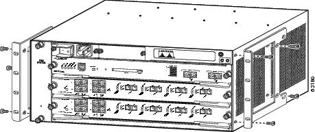
The Catalyst 6503 and the Catalyst 6503-E switch chassis are shipped with the two rack-mount brackets factory-installed on the front sides of the chassis. The rack-mount brackets are secured to the chassis with eight M3 Phillips-head countersunk screws (four screws on each side) as shown in Figure 1-1.
Note![]() The Catalyst 6503-E chassis has a chassis shipping bracket installed across the module slots. The bracket has been removed for clarity in Figure 1-1. The Catalyst 6503 switch chassis does not have this shipping bracket.
The Catalyst 6503-E chassis has a chassis shipping bracket installed across the module slots. The bracket has been removed for clarity in Figure 1-1. The Catalyst 6503 switch chassis does not have this shipping bracket.
Note![]() The rack-mount brackets can also be reversed and installed on the rear of the chassis as an alternative method of installation.
The rack-mount brackets can also be reversed and installed on the rear of the chassis as an alternative method of installation.
Figure 1-1 Rack-Mount Brackets on the Catalyst 6503 and the Catalyst 6503-E Switch Chassis
Rack-Mounting the Chassis
Note![]() The chassis are designed to be mounted in equipment racks that meet ANSI/EIA 310-D and ETS 300-119 standards.
The chassis are designed to be mounted in equipment racks that meet ANSI/EIA 310-D and ETS 300-119 standards.
Warning![]() Two people are required to lift the chassis. To prevent injury, keep your back straight and lift with your legs, not your back. Statement 164
Two people are required to lift the chassis. To prevent injury, keep your back straight and lift with your legs, not your back. Statement 164
Tip![]() We recommend that you have a third person to assist in this procedure.
We recommend that you have a third person to assist in this procedure.
To install the switch chassis into the equipment rack, follow these steps:
Step 1![]() Determine the positioning of the chassis in the rack enclosure. Identify the rack post holes that will be used. If the rack post holes are prethreaded, determine if the threads are 10-32 or 12-24. If the rack post holes are unthreaded, install either 10-32 or 12-24 clip or cage nuts over the holes to accept the installation screws.
Determine the positioning of the chassis in the rack enclosure. Identify the rack post holes that will be used. If the rack post holes are prethreaded, determine if the threads are 10-32 or 12-24. If the rack post holes are unthreaded, install either 10-32 or 12-24 clip or cage nuts over the holes to accept the installation screws.
Note![]() Clip or cage nuts are not included as part of the accessory kit that comes with the chassis. You must obtain them yourself.
Clip or cage nuts are not included as part of the accessory kit that comes with the chassis. You must obtain them yourself.
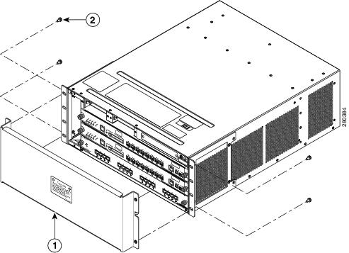
Step 2![]() If you are installing a Catalyst 6503-E switch chassis, you must remove the chassis shipping bracket before you install the chassis in the rack. Perform the following substeps:
If you are installing a Catalyst 6503-E switch chassis, you must remove the chassis shipping bracket before you install the chassis in the rack. Perform the following substeps:
a.![]() Loosen and remove the four M5 screws that secure the chassis shipping bracket to the chassis rack mount brackets. (See Figure 1-2.)
Loosen and remove the four M5 screws that secure the chassis shipping bracket to the chassis rack mount brackets. (See Figure 1-2.)
b.![]() Lift up slightly on the shipping bracket to disengage the two bracket hooks from the rack-mount brackets.
Lift up slightly on the shipping bracket to disengage the two bracket hooks from the rack-mount brackets.
c.![]() Remove the shipping bracket and save it. You must reinstall the shipping bracket if you relocate the chassis.
Remove the shipping bracket and save it. You must reinstall the shipping bracket if you relocate the chassis.
Figure 1-2 Removing the Catalyst 6503-E Chassis Shipping Bracket
|
|
|
Step 3![]() With a person standing at each side of the chassis, grasp the chassis handle with one hand, and use the other hand near the back of the chassis for balance. Slowly lift the chassis in unison. Avoid sudden twists or moves to prevent injury.
With a person standing at each side of the chassis, grasp the chassis handle with one hand, and use the other hand near the back of the chassis for balance. Slowly lift the chassis in unison. Avoid sudden twists or moves to prevent injury.
Tip![]() Have a third person install the rack-mount screws while two people support the chassis in the rack enclosure.
Have a third person install the rack-mount screws while two people support the chassis in the rack enclosure.
Step 4![]() Align the mounting holes in the rack-mount bracket with the mounting holes in the equipment rack.
Align the mounting holes in the rack-mount bracket with the mounting holes in the equipment rack.
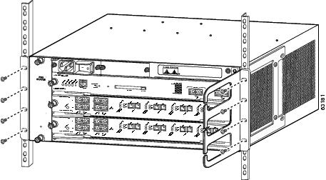
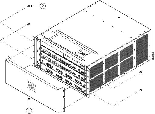
Step 5![]() If you want to install one or both of the optional cable guides, position the cable guide so that the cable guide mounting holes are aligned with rack-mount holes and the rack post holes. (See Figure 1-3.)
If you want to install one or both of the optional cable guides, position the cable guide so that the cable guide mounting holes are aligned with rack-mount holes and the rack post holes. (See Figure 1-3.)
Step 6![]() Install a minimum of eight 10-32 or 12-24 screws (four on each side) through the cable guide mounting holes, rack-mount bracket holes, rack post holes, and into the clip nuts to secure the cable guides and the chassis to the rack post. (See Figure 1-3.)
Install a minimum of eight 10-32 or 12-24 screws (four on each side) through the cable guide mounting holes, rack-mount bracket holes, rack post holes, and into the clip nuts to secure the cable guides and the chassis to the rack post. (See Figure 1-3.)
Step 7![]() Use a tape measure or level to verify that the chassis is installed straight and level.
Use a tape measure or level to verify that the chassis is installed straight and level.
Figure 1-3 Installing a Catalyst 6503 or Catalyst 6503-E Switch Chassis in a Rack
What is Next
After installing the chassis in its location, complete the installation process by following these procedures:
- Connecting the chassis to system ground. See “Establishing the System Ground” section.
- Installing and connecting the Power Entry Modules (PEMs) and the power supplies to source power. Go to Chapter 4 for information on how to install and cable the PEMs and the power supplies.
- Connecting the network interface cables to the supervisor engine and modules. This may involve installing transceivers before you attach the network interface cables. See “Attaching the Interface Cables” section.
- Powering-up the chassis and verifying the installation. See “Verifying Switch Chassis Installation” section.
Optional Installation Kits
There are no optional installation kits available for either the Catalyst 6503 or the Catalyst 6503-E switch chassis.
Installing a Catalyst 6504-E Switch Chassis
This section provides procedures for installing a Catalyst 6504-E switch chassis in a rack assembly and installing the optional cable guide assemblies.
Installation Accessory Kit
The Catalyst 6504-E switch chassis is designed to be installed in a standard 19-inch rack, either open or enclosed. The chassis is shipped with the 19-inch rack-mount L brackets factory installed on the left-front and right-front of the chassis. Included in the accessory kit are both 10-32 x 0.75-inch and 12-24 x 0.75-inch screws that are used to secure the chassis in the rack.
Note![]() Depending on the manufacturer, the rack posts might be prethreaded to accept either 10-32 or 12-24 screws. If the rack posts are not prethreaded, you must install 10-32 or 12-24 clip nuts or cage nuts to secure the rack-mount screws. The clip nuts or the cage nuts are not included as part of the accessory kit and must be obtained on your own.
Depending on the manufacturer, the rack posts might be prethreaded to accept either 10-32 or 12-24 screws. If the rack posts are not prethreaded, you must install 10-32 or 12-24 clip nuts or cage nuts to secure the rack-mount screws. The clip nuts or the cage nuts are not included as part of the accessory kit and must be obtained on your own.
Also included in the accessory kit are two optional cable guides. The two cable guides are installed on the front left- and right-side of the chassis using the same sets of screws (10-32 or 12-24) that secure the chassis rack-mount L brackets to the rack posts.
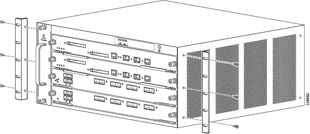
L Brackets on the Catalyst 6504-E Switch Chassis
The Catalyst 6504-E switch chassis is shipped with the two L brackets installed on the front sides of the chassis. The L brackets are secured to the chassis with six M4 Phillips-head countersunk screws (three screws on each side) as shown in Figure 1-4.
Note![]() The Catalyst 6504-E chassis has a chassis shipping bracket installed across the module slots. The bracket has been removed in Figure 1-4 for clarity.
The Catalyst 6504-E chassis has a chassis shipping bracket installed across the module slots. The bracket has been removed in Figure 1-4 for clarity.
Note![]() The L brackets can also be reversed and installed on the rear of the chassis as an alternative method of installation.
The L brackets can also be reversed and installed on the rear of the chassis as an alternative method of installation.
Figure 1-4 L Brackets on the Catalyst 6504-E Switch Chassis
Rack-Mounting the Chassis
Note![]() The chassis are designed to be mounted in equipment racks that meet ANSI/EIA 310-D and ETS 300-119 standards.
The chassis are designed to be mounted in equipment racks that meet ANSI/EIA 310-D and ETS 300-119 standards.
Warning![]() Two people are required to lift the chassis. To prevent injury, keep your back straight and lift with your legs, not your back. Statement 164
Two people are required to lift the chassis. To prevent injury, keep your back straight and lift with your legs, not your back. Statement 164
Tip![]() We recommend that you have a third person to assist in this procedure.
We recommend that you have a third person to assist in this procedure.
To install the switch chassis into the equipment rack, follow these steps:
Step 1![]() Determine the positioning of the chassis in the rack enclosure. Identify the rack post holes that will be used. If the rack post holes are prethreaded, determine if the threads are 10-32 or 12-24. If the rack post holes are unthreaded, install either 10-32 or 12-24 clip or cage nuts over the holes to accept the installation screws.
Determine the positioning of the chassis in the rack enclosure. Identify the rack post holes that will be used. If the rack post holes are prethreaded, determine if the threads are 10-32 or 12-24. If the rack post holes are unthreaded, install either 10-32 or 12-24 clip or cage nuts over the holes to accept the installation screws.
Note![]() Clip or cage nuts are not included as part of the accessory kit that comes with the chassis. You must obtain them yourself.
Clip or cage nuts are not included as part of the accessory kit that comes with the chassis. You must obtain them yourself.
Step 2![]() Remove the chassis shipping bracket before you install the chassis in the rack. Perform the following substeps:
Remove the chassis shipping bracket before you install the chassis in the rack. Perform the following substeps:
a.![]() Loosen and remove the four M5 screws that secure the chassis shipping bracket to the chassis rack mount brackets. (See Figure 1-5.)
Loosen and remove the four M5 screws that secure the chassis shipping bracket to the chassis rack mount brackets. (See Figure 1-5.)
b.![]() Lift up slightly on the shipping bracket to disengage the two shipping bracket hooks from the rack-mount L brackets.
Lift up slightly on the shipping bracket to disengage the two shipping bracket hooks from the rack-mount L brackets.
c.![]() Remove the shipping bracket and save it. You must reinstall the shipping bracket if you relocate the chassis.
Remove the shipping bracket and save it. You must reinstall the shipping bracket if you relocate the chassis.
Figure 1-5 Removing the Catalyst 6504-E Chassis Shipping Bracket
|
|
|
Step 3![]() With a person standing at each side of the chassis, grasp the chassis handle with one hand, and use the other hand near the back of the chassis for balance. Slowly lift the chassis in unison. Avoid sudden twists or moves to prevent injury.
With a person standing at each side of the chassis, grasp the chassis handle with one hand, and use the other hand near the back of the chassis for balance. Slowly lift the chassis in unison. Avoid sudden twists or moves to prevent injury.
Tip![]() Have a third person install the rack-mount screws while two people support the chassis in the rack enclosure.
Have a third person install the rack-mount screws while two people support the chassis in the rack enclosure.
Step 4![]() Align the mounting holes in the rack-mount bracket with the mounting holes in the equipment rack.
Align the mounting holes in the rack-mount bracket with the mounting holes in the equipment rack.
Step 5![]() If you want to install one or both of the optional cable guides, position the cable guides so that the cable guide mounting holes are aligned with rack-mount holes and the rack post holes.
If you want to install one or both of the optional cable guides, position the cable guides so that the cable guide mounting holes are aligned with rack-mount holes and the rack post holes.
Step 6![]() Install a minimum of eight 10-32 or 12-24 screws (four on each side) through the cable guide mounting holes, rack-mount bracket holes, rack post holes, and into the clip nuts to secure the cable guides and the chassis to the rack post. (See Figure 1-6.)
Install a minimum of eight 10-32 or 12-24 screws (four on each side) through the cable guide mounting holes, rack-mount bracket holes, rack post holes, and into the clip nuts to secure the cable guides and the chassis to the rack post. (See Figure 1-6.)
Step 7![]() Use a tape measure or a level to verify that the chassis is installed straight and level.
Use a tape measure or a level to verify that the chassis is installed straight and level.
Figure 1-6 Installing a Catalyst 6504-E Switch Chassis in a Rack
What is Next
After installing the chassis in its location, continue with the installation process by following these procedures:
- Connecting the chassis to system ground. See “Establishing the System Ground” section.
- Installing and connecting the power supplies to source power. Go to Chapter 4 for information on how to install and cable power supplies.
- Connecting the network interface cables to the supervisor engine and modules. This may involve installing transceivers before you attach the network interface cables. See “Attaching the Interface Cables” section.
- Powering-up the chassis and verifying the installation. See “Verifying Switch Chassis Installation” section.
Optional Installation Kits
There are no optional installation kits available for the Catalyst 6504-E switch chassis.
Installing a Catalyst 6506 or Catalyst 6506-E Switch Chassis
This section provides procedures for installing either a Catalyst 6506 or a Catalyst 6506-E switch chassis in a rack assembly and installing the optional cable guide assemblies.
Installation Accessory Kits
The Catalyst 6506 and Catalyst 6506-E switch chassis are designed to be installed in a standard 19-inch rack, either open or enclosed. Both chassis are normally shipped with the 19-inch rack-mount L brackets factory installed on the left-front and right-front of the chassis. Included with the accessory kit are 10-32 x 0.75-inch and 12-24 x 0.75-inch screws that are used to secure the chassis in the rack enclosure.
Note![]() Depending on the manufacturer, the rack posts might be prethreaded to accept either 10-32 or 12-24 screws. If the rack posts are not prethreaded, you must install 10-32 or 12-24 clip nuts or cage nuts to secure the rack-mount screws. The clip nuts or the cage nuts are not included as part of the accessory kit and must be obtained on your own.
Depending on the manufacturer, the rack posts might be prethreaded to accept either 10-32 or 12-24 screws. If the rack posts are not prethreaded, you must install 10-32 or 12-24 clip nuts or cage nuts to secure the rack-mount screws. The clip nuts or the cage nuts are not included as part of the accessory kit and must be obtained on your own.
Depending on the chassis model, the accessory kit might also contain the following chassis installation kits:
- Rack-mount shelf kit (Catalyst 6506 and Catalyst 6506-E). The rack-mount shelf kit is used to support the weight of the chassis while you secure the chassis L brackets to the rack enclosure.
- Rubber feet mount kit (Catalyst 6506-E accessory kit only). This kit should installed when you want to install the Catalyst 6506-E chassis as a freestanding unit on a shelf or a table.
Also included in the accessory kit:
- Two optional cable guides—The two cable guides are installed on the front left- and right-sides of the chassis using the same sets of screws (either 10-32 or 12-24) that secure the chassis rack-mount L brackets to the rack posts.
- Power supply blank panel—The power supply blank panel must be installed on an unused power supply bay to maintain chassis airflow and EMI shielding.
L Brackets on the Catalyst 6506 and the Catalyst 6506-E Switch Chassis
The Catalyst 6506 and the Catalyst 6506-E switch chassis are shipped with two L brackets installed on the front sides of the chassis. The L brackets are secured to the chassis with eight M3 Phillips-head countersunk screws (four M3 screws on each side) as shown in Figure 1-7.
Note![]() The L brackets can also be reversed and installed on the rear of the chassis as an alternative method of installation.
The L brackets can also be reversed and installed on the rear of the chassis as an alternative method of installation.
Note![]() The L brackets for the Catalyst 6506 and Catalyst 6506-E switches are stamped with an L and an R to identify them as left and right.
The L brackets for the Catalyst 6506 and Catalyst 6506-E switches are stamped with an L and an R to identify them as left and right.
Figure 1-7 L Brackets on the Catalyst 6506 and the Catalyst 6506-E Switch Chassis
|
|
|
Installing the 3 RU Rack-Mount Shelf Kit
The 3 RU rack-mount shelf kit is included as part of the accessory kit for both the Catalyst 6506 and the Catalyst 6506-E switch chassis. You need to install this kit first before you install the chassis in the rack. The shelf kit supports the weight of the chassis while you install and secure the chassis in the rack.
The procedure for installing the shelf kit is located at “Installing the 3 RU Rack-Mount Shelf Kit” section.
Rack-Mounting the Chassis
Note![]() The chassis are designed to be mounted in equipment racks that meet ANSI/EIA 310-D and ETS 300-119 standards.
The chassis are designed to be mounted in equipment racks that meet ANSI/EIA 310-D and ETS 300-119 standards.
Warning![]() Two people are required to lift the chassis. To prevent injury, keep your back straight and lift with your legs, not your back. Statement 164
Two people are required to lift the chassis. To prevent injury, keep your back straight and lift with your legs, not your back. Statement 164
Tip![]() We recommend that you have a third person to assist in this procedure.
We recommend that you have a third person to assist in this procedure.
To install the switch chassis into the equipment rack, follow these steps:
Step 1![]() With a person standing at each side of the chassis, grasp the chassis handle with one hand, and use the other hand near the back of the chassis for balance. Slowly lift the chassis in unison. Avoid sudden twists or moves to prevent injury.
With a person standing at each side of the chassis, grasp the chassis handle with one hand, and use the other hand near the back of the chassis for balance. Slowly lift the chassis in unison. Avoid sudden twists or moves to prevent injury.
Step 2![]() Rest the back end of the chassis on the edges of the rack-mount shelf kit rails and carefully slide the chassis fully into the rack.
Rest the back end of the chassis on the edges of the rack-mount shelf kit rails and carefully slide the chassis fully into the rack.
Step 3![]() Locate the rack post holes that align with the chassis L bracket holes. If the rack post holes are prethreaded, determine if the threads are 10-32 or 12-24. If the rack post holes are unthreaded, install a minimum of eight (four on each side) either 10-32 or 12-24 clip or cage nuts over the rack post holes to accept the installation screws.
Locate the rack post holes that align with the chassis L bracket holes. If the rack post holes are prethreaded, determine if the threads are 10-32 or 12-24. If the rack post holes are unthreaded, install a minimum of eight (four on each side) either 10-32 or 12-24 clip or cage nuts over the rack post holes to accept the installation screws.
Note![]() Clip nuts or cage nuts are not included as part of the accessory kit that comes with the chassis. You must obtain them yourself.
Clip nuts or cage nuts are not included as part of the accessory kit that comes with the chassis. You must obtain them yourself.
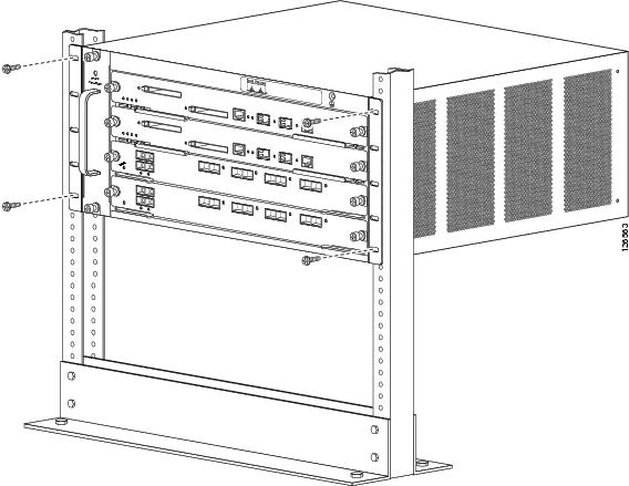
Step 4![]() If you want to install one or both of the optional cable guides, position the cable guides so that the cable guide mounting holes are aligned with rack-mount bracket holes and the rack post holes. (See Figure 1-8.)
If you want to install one or both of the optional cable guides, position the cable guides so that the cable guide mounting holes are aligned with rack-mount bracket holes and the rack post holes. (See Figure 1-8.)
Step 5![]() Install a minimum of eight 10-32 or 12-24 screws (four on each side) through the cable guide mounting holes, rack-mount L bracket holes, rack post holes, and into the clip nuts to secure the cable guides and the chassis to the rack post. Tighten the screws securely.
Install a minimum of eight 10-32 or 12-24 screws (four on each side) through the cable guide mounting holes, rack-mount L bracket holes, rack post holes, and into the clip nuts to secure the cable guides and the chassis to the rack post. Tighten the screws securely.
Figure 1-8 Installing a Catalyst 6506 or a Catalyst 6506-E Switch in a Rack
What is Next
After installing the chassis in its location, complete the installation process by following these procedures:
- Connecting the chassis to system ground. See “Establishing the System Ground” section.
- Installing and connecting the power supplies to source power. Go to Chapter 4 for information on how to install and cable power supplies.
- Connecting the network interface cables to the supervisor engine and modules. This may involve installing transceivers before you attach the network interface cables. See “Attaching the Interface Cables” section.
- Powering-up the chassis and verifying the installation. See “Verifying Switch Chassis Installation” section.
Optional Installation Kits
An optional rubber feet installation kit is included in the accessory kit for the Catalyst 6506-E switch chassis. This kit contains the parts necessary to install four non-slip rubber feet on the bottom of the chassis allowing the chassis to placed on a shelf or a table. To install the rubber feet, go to “Installing the Rubber Feet Kit” section.
A center rack-mount kit for 23-inch, telco-style racks is available as an option for both the Catalyst 6506 and the Catalyst 6506-E switch chassis. The kit is not included in the accessory kits, but is available as a separately orderable item (p/n WS-C6597=). Installation instructions are included with the kit.
Installing a Catalyst 6509 or Catalyst 6509-E Switch Chassis
This section provides procedures for installing either a Catalyst 6509 or a Catalyst 6509-E switch chassis in a rack assembly and installing the optional cable guide assemblies.
Installation Accessory Kits
The Catalyst 6509 and Catalyst 6509-E switch chassis are designed to be installed in a standard 19-inch rack, either open or enclosed. Both chassis are normally shipped with the 19-inch rack-mount L brackets factory installed on the left-front and right-front of the chassis. Included with the accessory kit are 10-32 x 0.75-inch and 12-24 x 0.75-inch screws that are used to secure the chassis in the rack enclosure.
Note![]() Depending on the manufacturer, the rack posts might be prethreaded to accept either 10-32 or 12-24 screws. If the rack posts are not prethreaded, you must install 10-32 or 12-24 clip nuts or cage nuts to secure the rack-mount screws. The clip nuts or the cage nuts are not included as part of the accessory kit and must be obtained on your own.
Depending on the manufacturer, the rack posts might be prethreaded to accept either 10-32 or 12-24 screws. If the rack posts are not prethreaded, you must install 10-32 or 12-24 clip nuts or cage nuts to secure the rack-mount screws. The clip nuts or the cage nuts are not included as part of the accessory kit and must be obtained on your own.
Depending on the chassis model, the accessory kit might also contain the following chassis installation kits:
- Rack-mount shelf kit (Catalyst 6509 and Catalyst 6509-E). The rack-mount shelf kit is used to support the weight of the chassis while you secure the chassis L brackets to the rack enclosure.
- Rubber feet mount kit (Catalyst 6509-E accessory kit only). This kit can be installed when you want to install the Catalyst 6509-E chassis as a freestanding unit on a shelf or a table.
Also included in the accessory kit:
- Cable guides— Two cable guides can be installed on the front of the chassis using the same sets of screws that secure the chassis rack-mount brackets to the rack posts.
- Power supply blank panel—The power supply blank panel must be installed on an unused power supply bay to maintain chassis airflow and EMI shielding.
L Brackets on the Catalyst 6509 and Catalyst 6509-E Switches
The Catalyst 6509 and Catalyst 6509-E switch chassis are shipped with two L brackets installed on the front sides of the chassis. The L brackets are secured to the chassis with ten M3 Phillips-head countersunk screws (five M3 screws on each side) as shown in Figure 1-9.
Note![]() The L brackets can also be reversed and installed on the rear of the chassis as an alternative method of installation.
The L brackets can also be reversed and installed on the rear of the chassis as an alternative method of installation.
Note![]() The L brackets for the Catalyst 6509 and the Catalyst 6509-E switches are stamped with an L and an R to identify them as left and right.
The L brackets for the Catalyst 6509 and the Catalyst 6509-E switches are stamped with an L and an R to identify them as left and right.
Figure 1-9 L Brackets on the Catalyst 6509 and the Catalyst 6509-E Switch Chassis
|
|
|
Installing the 3 RU Rack-Mount Shelf Kit
The 3 RU rack-mount shelf kit is included as part of the accessory kit for both the Catalyst 6509 and the Catalyst 6509-E switch chassis. You need to install this kit first before you install the chassis in the rack. The shelf kit supports the weight of the chassis while you install and secure the chassis in the rack.
The procedure for installing the shelf kit is located at “Installing the 3 RU Rack-Mount Shelf Kit” section.
Rack-Mounting the Chassis
Note![]() The chassis are designed to be mounted in equipment racks that meet ANSI/EIA 310-D and ETS 300-119 standards.
The chassis are designed to be mounted in equipment racks that meet ANSI/EIA 310-D and ETS 300-119 standards.
Warning![]() Two people are required to lift the chassis. To prevent injury, keep your back straight and lift with your legs, not your back. Statement 164
Two people are required to lift the chassis. To prevent injury, keep your back straight and lift with your legs, not your back. Statement 164
Tip![]() We recommend that you have a third person to assist in this procedure.
We recommend that you have a third person to assist in this procedure.
To install the switch chassis in the equipment rack, follow these steps:
Step 1![]() With a person standing at each side of the chassis, grasp the chassis handle with one hand, and use the other hand near the back of the chassis for balance. Slowly lift the chassis in unison. Avoid sudden twists or moves to prevent injury.
With a person standing at each side of the chassis, grasp the chassis handle with one hand, and use the other hand near the back of the chassis for balance. Slowly lift the chassis in unison. Avoid sudden twists or moves to prevent injury.
Step 2![]() Rest the back end of the chassis on the edges of the rack-mount shelf kit rails and carefully slide the chassis fully into the rack.
Rest the back end of the chassis on the edges of the rack-mount shelf kit rails and carefully slide the chassis fully into the rack.
Step 3![]() Locate the rack post holes that align with the chassis L bracket holes. If the rack post holes are prethreaded, determine if the threads are 10-32 or 12-24. If the rack post holes are unthreaded, install eight or ten (four or five on each side) either 10-32 or 12-24 clip or cage nuts over the rack post holes to accept the installation screws.
Locate the rack post holes that align with the chassis L bracket holes. If the rack post holes are prethreaded, determine if the threads are 10-32 or 12-24. If the rack post holes are unthreaded, install eight or ten (four or five on each side) either 10-32 or 12-24 clip or cage nuts over the rack post holes to accept the installation screws.
Note![]() Clip nuts or cage nuts are not included as part of the accessory kit that comes with the chassis. You must obtain them yourself.
Clip nuts or cage nuts are not included as part of the accessory kit that comes with the chassis. You must obtain them yourself.
Step 4![]() If you want to install one or both of the optional cable guide assemblies, position the cable guides so that the cable guide mounting holes are aligned with rack-mount bracket holes and the rack post holes as shown in Figure 1-10.
If you want to install one or both of the optional cable guide assemblies, position the cable guides so that the cable guide mounting holes are aligned with rack-mount bracket holes and the rack post holes as shown in Figure 1-10.
Step 5![]() Install a minimum of eight 10-32 or 12-24 screws (four on each side) through the cable guide mounting holes, rack-mount L bracket holes, rack post holes, and into the clip nuts to secure the cable guides and the chassis to the rack post. Tighten the screws securely.
Install a minimum of eight 10-32 or 12-24 screws (four on each side) through the cable guide mounting holes, rack-mount L bracket holes, rack post holes, and into the clip nuts to secure the cable guides and the chassis to the rack post. Tighten the screws securely.
Figure 1-10 Installing a Catalyst 6509 Switch or a Catalyst 6509-E Switch Chassis in a Rack

What is Next
After installing the chassis in its location, complete the installation process by following these procedures:
- Connecting the chassis to system ground. See “Establishing the System Ground” section.
- Installing and connecting the power supplies to source power. Go to Chapter 4 for information on how to install and cable power supplies.
- Connecting the network interface cables to the supervisor engine and modules. This may involve installing transceivers before you attach the network interface cables. See “Attaching the Interface Cables” section.
- Powering-up the chassis and verifying the installation. See “Verifying Switch Chassis Installation” section.
Optional Installation Kits
An optional rubber feet installation kit is included in the accessory kit for the Catalyst 6509-E switch chassis. This kit contains the parts necessary to install four non-slip rubber feet on the bottom of the chassis allowing the chassis to placed on a shelf or a table. To install the rubber feet, go to “Installing the Rubber Feet Kit” section.
A center rack-mount kit for 23-inch, telco-style racks is available as an option for both the Catalyst 6509 and the Catalyst 6509-E switch chassis. The kit is not included in the accessory kits, but is available as a separately orderable item (p/n WS-C6597=). Installation instructions are included with the kit.
Installing a Catalyst 6509-NEB or Catalyst 6509-NEB-A Switch Chassis
This section provides procedures for installing either a Catalyst 6509-NEB or a Catalyst 6509-NEB-A switch chassis in a rack assembly and installing the optional cable guides.
Installation Accessory Kits
The Catalyst 6509-NEB and Catalyst 6509-NEB-A switch chassis are designed to be installed in a standard 19-inch rack, either open or enclosed. Both chassis are normally shipped with the 19-inch rack-mount L brackets factory installed on the left-front and right-front of the chassis. Included with the accessory kit are 10-32 x 0.75-inch and 12-24 x 0.75-inch screws that are used to secure the chassis in the rack enclosure.
Note![]() Depending on the manufacturer, the rack posts might be prethreaded to accept either 10-32 or 12-24 screws. If the rack posts are not prethreaded, you must install 10-32 or 12-24 clip nuts or cage nuts to secure the rack-mount screws. The clip nuts or the cage nuts are not included as part of the accessory kit and must be obtained on your own.
Depending on the manufacturer, the rack posts might be prethreaded to accept either 10-32 or 12-24 screws. If the rack posts are not prethreaded, you must install 10-32 or 12-24 clip nuts or cage nuts to secure the rack-mount screws. The clip nuts or the cage nuts are not included as part of the accessory kit and must be obtained on your own.
Depending on the chassis model, the accessory kit might contain the following chassis installation kits:
- Rack-mount shelf kit (Catalyst 6509-NEB and Catalyst 6509-NEB-A). The rack-mount shelf kit is used to support the weight of the chassis while you secure the chassis L brackets to the rack enclosure.
- A stabilizer bracket kit (Catalyst 6509-NEB only). If you are not installing the Catalyst 6509-NEB switch in a rack, you must install the stabilizer brackets to the bottom of the chassis. The stabilizer brackets reduce the possibility that the freestanding switch chassis will tip over.
L Brackets and the Optional Cable Guide on the Catalyst 6509-NEB Switch
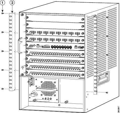
The Catalyst 6509-NEB switch chassis is shipped with the two L brackets installed on the front sides of the chassis. The L brackets are secured to the chassis with eight M4 Phillips-head countersunk screws (four screws on each side) as shown in Figure 1-12.
Note![]() The L brackets can also be reversed and installed on the rear of the chassis as an alternative method of installation.
The L brackets can also be reversed and installed on the rear of the chassis as an alternative method of installation.
Note![]() The Catalyst 6509-NEB L bracket screw holes are stamped + and –. You can install the brackets on either the left or right side of the chassis; use the + holes on one side and the – holes on the other side.
The Catalyst 6509-NEB L bracket screw holes are stamped + and –. You can install the brackets on either the left or right side of the chassis; use the + holes on one side and the – holes on the other side.
The optional cable guide attaches to the front of the chassis using four M4 screws supplied in the accessory kit. (See Figure 1-11.)
Figure 1-11 L Brackets and Cable Guide Attachment on the Catalyst 6509-NEB Switch Chassis
L Brackets on the Catalyst 6509-NEB-A Switch Chassis
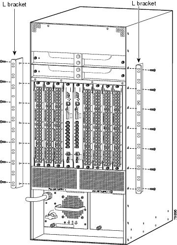
The Catalyst 6509-NEB-A switch chassis is shipped with the two L brackets installed on the front sides of the chassis. The L brackets are secured to the chassis with 14 M3 Phillips-head countersunk screws (seven screws on each side) as shown in Figure 1-12. These brackets can also be installed on the rear of the chassis if necessary.
Figure 1-12 L Brackets on the Catalyst 6509-NEB-A Switch Chassis
Installing the 3 RU Rack-Mount Shelf Kit
The 3 RU rack-mount shelf kit is included as part of the accessory kit for both the Catalyst 6509-NEB and the Catalyst 6509-NEB-A switch chassis. You need to install this kit first before you install the chassis in the rack. The shelf kit supports the weight of the chassis while you install the chassis in the rack.
The procedure for installing the shelf kit is located in the “Installing the 3 RU Rack-Mount Shelf Kit” section.
Rack-Mounting the Chassis
This section provides procedures for installing either the Catalyst 6509-NEB or the Catalyst 6509-NEB-A switch chassis in a 19-inch rack enclosure.
Note![]() The chassis are designed to be mounted in equipment racks that meet ANSI/EIA 310-D and ETS 300-119 standards.
The chassis are designed to be mounted in equipment racks that meet ANSI/EIA 310-D and ETS 300-119 standards.
Warning![]() Two people are required to lift the chassis. To prevent injury, keep your back straight and lift with your legs, not your back. Statement 164
Two people are required to lift the chassis. To prevent injury, keep your back straight and lift with your legs, not your back. Statement 164
Tip![]() We recommend that you have a third person to assist in this procedure.
We recommend that you have a third person to assist in this procedure.
To install the switch chassis in the equipment rack, follow these steps:
Step 1![]() With a person standing at each side of the chassis, grasp the chassis handle with one hand, and use the other hand near the back of the chassis for balance. Slowly lift the chassis in unison. Avoid sudden twists or moves to prevent injury.
With a person standing at each side of the chassis, grasp the chassis handle with one hand, and use the other hand near the back of the chassis for balance. Slowly lift the chassis in unison. Avoid sudden twists or moves to prevent injury.
Step 2![]() Rest the back end of the chassis on the edges of the rack-mount shelf kit rails and carefully slide the chassis fully into the rack.
Rest the back end of the chassis on the edges of the rack-mount shelf kit rails and carefully slide the chassis fully into the rack.
Step 3![]() Locate the rack post holes that align with the chassis L bracket holes. If the rack post holes are prethreaded, determine if the threads are 10-32 or 12-24. If the rack post holes are unthreaded, install eight or ten (four or five on each side) either 10-32 or 12-24 clip or cage nuts over the rack post holes to accept the installation screws.
Locate the rack post holes that align with the chassis L bracket holes. If the rack post holes are prethreaded, determine if the threads are 10-32 or 12-24. If the rack post holes are unthreaded, install eight or ten (four or five on each side) either 10-32 or 12-24 clip or cage nuts over the rack post holes to accept the installation screws.
Note![]() Clip nuts or cage nuts are not included as part of the accessory kit that comes with the chassis. You must obtain them yourself.
Clip nuts or cage nuts are not included as part of the accessory kit that comes with the chassis. You must obtain them yourself.
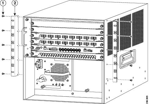
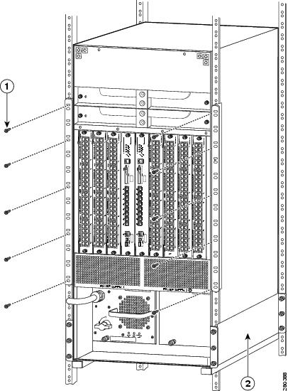
Step 4![]() Install a minimum of eight 10-32 or 12-24 screws (four on each side) through the cable guide mounting holes, rack-mount L bracket holes, rack post holes, and into the clip nuts to secure the cable guides and the chassis to the rack post, as shown in Figure 1-13. Tighten the screws securely.
Install a minimum of eight 10-32 or 12-24 screws (four on each side) through the cable guide mounting holes, rack-mount L bracket holes, rack post holes, and into the clip nuts to secure the cable guides and the chassis to the rack post, as shown in Figure 1-13. Tighten the screws securely.
Figure 1-13 Installing a Catalyst 6509-NEB or a Catalyst 6509-NEB-A Switch Chassis in a Rack
|
|
|
Installing the Cable Management System (Catalyst 6509-NEB-A Only)
This section describes the installation procedures for the cable management system (CABLETRAY-09) on the Catalyst 6509-NEB-A switch.
Note![]() The cable management system is shipped with the extended cable guide installed but can be used with the supplied standard cable guide. Use the extended cable guide with Ethernet and Fast Ethernet modules (24 to 48 ports) using 10/100 cable. Use the standard cable guide with low port-density modules (up to 16 ports) using fiber and coax cable. We recommend that you install the cable management system before replacing the cable guide. See the “Replacing the Cable Guide” section for replacement procedures.
The cable management system is shipped with the extended cable guide installed but can be used with the supplied standard cable guide. Use the extended cable guide with Ethernet and Fast Ethernet modules (24 to 48 ports) using 10/100 cable. Use the standard cable guide with low port-density modules (up to 16 ports) using fiber and coax cable. We recommend that you install the cable management system before replacing the cable guide. See the “Replacing the Cable Guide” section for replacement procedures.
To install the cable management system, perform these steps:
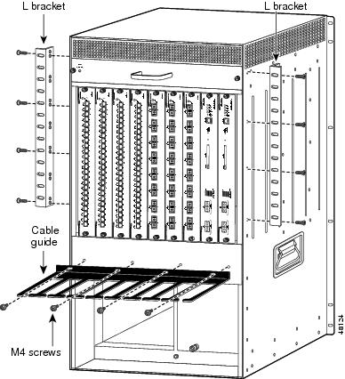
Step 1![]() Place the cable management system against the chassis, as shown in Figure 1-14, and tighten the captive installation screws.
Place the cable management system against the chassis, as shown in Figure 1-14, and tighten the captive installation screws.
Step 2![]() Assure that the hinge is flat against the chassis, and install four 6-32 screws to secure the back plate to the chassis.
Assure that the hinge is flat against the chassis, and install four 6-32 screws to secure the back plate to the chassis.
Figure 1-14 Installing the Catalyst 6509-NEB-A Cable Management System
Note![]() To route the cables through the cable guide, remove the front panel, and attach the interface cables to the modules. See the “Attaching the Interface Cables” section for information on attaching the interface cables.
To route the cables through the cable guide, remove the front panel, and attach the interface cables to the modules. See the “Attaching the Interface Cables” section for information on attaching the interface cables.
Step 3![]() Loosen the two captive installation screws on the front panel. (See Figure 1-15.)
Loosen the two captive installation screws on the front panel. (See Figure 1-15.)
Figure 1-15 Removing the Front Panel
Step 4![]() Remove the front panel, and set it aside.
Remove the front panel, and set it aside.
Step 5![]() Attach the interface cables to the modules, and route the cables through the cable guide.
Attach the interface cables to the modules, and route the cables through the cable guide.
Step 6![]() Install the front panel by positioning the top of the front panel over the cable guide.
Install the front panel by positioning the top of the front panel over the cable guide.
Step 7![]() Tighten the two captive installation screws. (See Figure 1-15.)
Tighten the two captive installation screws. (See Figure 1-15.)
Replacing the Cable Guide
To replace the cable guides on the cable management system, perform these steps:
Step 1![]() Loosen the two captive installation screws on the front panel. (See Figure 1-16.)
Loosen the two captive installation screws on the front panel. (See Figure 1-16.)
Figure 1-16 Removing the Front Panel
Step 2![]() Remove the front panel, and set it aside.
Remove the front panel, and set it aside.
Step 3![]() Remove the two screws that secure the cable guide to the back panel, and remove the cable guide by lifting it up and away from the back panel. (See Figure 1-17.)
Remove the two screws that secure the cable guide to the back panel, and remove the cable guide by lifting it up and away from the back panel. (See Figure 1-17.)
Figure 1-17 Removing the Cable Guide
Step 4![]() Install the standard cable guide to the back panel by securing the lip of the cable guide to the back panel. (See Figure 1-17.)
Install the standard cable guide to the back panel by securing the lip of the cable guide to the back panel. (See Figure 1-17.)
Step 5![]() Install the two screws to secure the cable guide to the back plate. (See Figure 1-17.)
Install the two screws to secure the cable guide to the back plate. (See Figure 1-17.)
Note![]() Before installing the front panel, attach the interface cables to the modules, and route the cables through the cable guide. See the “Attaching the Interface Cables” section for information on attaching the interface cables.
Before installing the front panel, attach the interface cables to the modules, and route the cables through the cable guide. See the “Attaching the Interface Cables” section for information on attaching the interface cables.
Step 6![]() Attach the interface cables to the modules, and route the cables through the cable guide.
Attach the interface cables to the modules, and route the cables through the cable guide.
Step 7![]() Install the front panel by hooking the top of the front panel over the cable guide.
Install the front panel by hooking the top of the front panel over the cable guide.
Step 8![]() Tighten the two captive installation screws. (See Figure 1-18.)
Tighten the two captive installation screws. (See Figure 1-18.)
Figure 1-18 Front Panel Installation
What is Next
After installing the chassis in its location, complete the installation process by performing these procedures:
- Connecting the chassis to system ground. See “Establishing the System Ground” section.
- Installing and connecting the power supplies to source power. Go to Chapter 4 for information on how to install and cable power supplies.
- Connecting the network interface cables to the supervisor engine and modules. This may involve installing transceivers before you attach the network interface cables. See “Attaching the Interface Cables” section.
- Powering-up the chassis and verifying the installation. See “Verifying Switch Chassis Installation” section.
Optional Installation Kits
The Catalyst 6509-NEB accessory kit has an optional stabilizer bracket installation kit included. This kit contains the parts necessary to install two brackets on the bottom of the chassis to provide additional stability for the chassis when the chassis is not rack mounted allowing the chassis to placed on a shelf or a table. To install the stabilizer brackets, go to “Installing the Stabilizer Bracket Kit” section.
Installing a Catalyst 6509-V-E Switch Chassis
This section provides procedures for installing a Catalyst 6509-V-E switch chassis in a rack assembly and installing the optional cable guide system.
Installation Accessory Kit
The Catalyst 6509-V-E switch chassis is designed to be installed in a standard 19-inch rack, either open or enclosed. The chassis is shipped with the 19-inch rack mount L brackets installed on the left-front and right-front of the chassis. Included in the accessory kit are 10-32 x 0.75-inch and 12-24 x 0.75-inch screws used to secure the chassis in the rack enclosure.
Note![]() Depending on the manufacturer, the rack posts might be prethreaded to accept either 10-32 or 12-24 screws. If the rack posts are not prethreaded, you must install 10-32 or 12-24 clip nuts or cage nuts to secure the rack-mount screws. The clip nuts or the cage nuts are not included as part of the accessory kit and must be obtained on your own.
Depending on the manufacturer, the rack posts might be prethreaded to accept either 10-32 or 12-24 screws. If the rack posts are not prethreaded, you must install 10-32 or 12-24 clip nuts or cage nuts to secure the rack-mount screws. The clip nuts or the cage nuts are not included as part of the accessory kit and must be obtained on your own.
Included in the accessory kit is the rack-mount shelf kit. The rack-mount shelf kit is used to support the weight of the chassis while you secure the chassis L brackets to the rack enclosure.
Also included in the Catalyst 6509-V-E switch accessory kit:
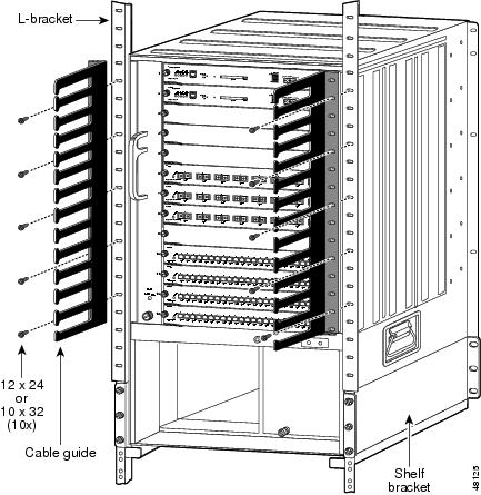
L Brackets on the Catalyst 6509-V-E Switch Chassis
The Catalyst 6509-V-E switch chassis is shipped with the two L brackets installed on the front sides of the chassis. Each L bracket is secured to the chassis with 14 M4 Phillips-head countersunk screws (seven screws on each side) as shown in Figure 1-19.
Note![]() The L brackets can also be reversed and installed on the rear of the chassis as an alternative method of installation.
The L brackets can also be reversed and installed on the rear of the chassis as an alternative method of installation.
Figure 1-19 L Brackets on the Catalyst 6509-V-E Switch Chassis
Installing the 3 RU Rack-Mount Shelf
The 3 RU rack-mount shelf is included as part of the accessory kit for the Catalyst 6509-V-E switch chassis. You need to install this kit first before you install the chassis in the rack. The shelf kit supports the weight of the chassis while you install the chassis in the rack.
The procedure for installing the shelf kit is located in the “Installing the 3 RU Rack-Mount Shelf Kit” section.
Rack-Mounting the Chassis
Tip![]() We recommend that you have a third person to assist in this procedure.
We recommend that you have a third person to assist in this procedure.
Warning![]() Two people are required to lift the chassis. To prevent injury, keep your back straight and lift with your legs, not your back. Statement 164
Two people are required to lift the chassis. To prevent injury, keep your back straight and lift with your legs, not your back. Statement 164
To install the switch chassis in the equipment rack, follow these steps:
Step 1![]() With a person standing at each side of the chassis, grasp the chassis handle with one hand, and use the other hand near the back of the chassis for balance. Slowly lift the chassis in unison. Avoid sudden twists or moves to prevent injury.
With a person standing at each side of the chassis, grasp the chassis handle with one hand, and use the other hand near the back of the chassis for balance. Slowly lift the chassis in unison. Avoid sudden twists or moves to prevent injury.
Step 2![]() Position the chassis in the rack as follows:
Position the chassis in the rack as follows:
a.![]() If the front of the chassis (front panel) is at the front of the rack, insert the rear of the chassis between the mounting posts, resting the chassis on the shelf brackets, and then carefully slide the chassis into the rack.
If the front of the chassis (front panel) is at the front of the rack, insert the rear of the chassis between the mounting posts, resting the chassis on the shelf brackets, and then carefully slide the chassis into the rack.
b.![]() If the rear of the chassis is at the front of the rack, insert the front of the chassis between the mounting posts, resting the chassis on the shelf brackets, and then carefully slide the chassis into the rack.
If the rear of the chassis is at the front of the rack, insert the front of the chassis between the mounting posts, resting the chassis on the shelf brackets, and then carefully slide the chassis into the rack.
Step 3![]() Align the mounting holes in the L bracket with the mounting holes in the equipment rack.
Align the mounting holes in the L bracket with the mounting holes in the equipment rack.
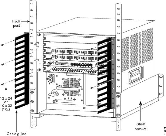
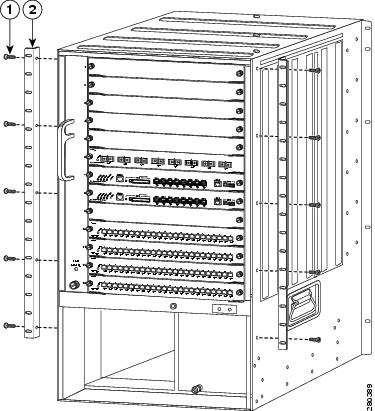
Step 4![]() Install the eight or ten (four or five per side) 12-24 x 3/4-inch or 10-32 x 3/4-inch screws through the holes in the L bracket mounting holes, and into the threaded holes in the equipment rack posts. (See Figure 1-20.)
Install the eight or ten (four or five per side) 12-24 x 3/4-inch or 10-32 x 3/4-inch screws through the holes in the L bracket mounting holes, and into the threaded holes in the equipment rack posts. (See Figure 1-20.)
Step 5![]() Use a tape measure and level to verify that the chassis is installed straight and level.
Use a tape measure and level to verify that the chassis is installed straight and level.
Figure 1-20 Installing a Catalyst 6509-V-E Switch Chassis in a Rack
|
|
|
Installing the Cable Management System (Optional)
The accessory kit for the Catalyst 6509-V-E switch chassis includes an optional cable management system that is installed on the front of the switch chassis. This cable management system is only available for the Catalyst 6509-V-E switch chassis.
Note![]() The cable management system adds an additional 6.8 inches (17.3 cm) (measured to the outside of the thumbscrews) to the overall depth of the chassis.
The cable management system adds an additional 6.8 inches (17.3 cm) (measured to the outside of the thumbscrews) to the overall depth of the chassis.
To install the cable management system on the chassis, perform the following steps:
Step 1![]() Remove the cable management assembly from the packing material.
Remove the cable management assembly from the packing material.
Step 2![]() Locate the bag containing the four 6-32 screws that accompanied the cable management assembly.
Locate the bag containing the four 6-32 screws that accompanied the cable management assembly.
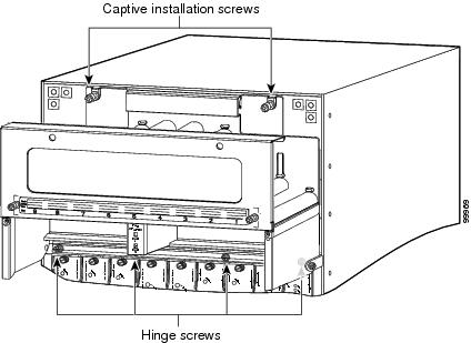
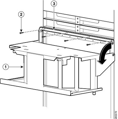
Step 3![]() Loosen the two captive screws on the inside of the cable management assembly and pivot the cable guide assembly away from the attachment bracket. (See Figure 1-21.)
Loosen the two captive screws on the inside of the cable management assembly and pivot the cable guide assembly away from the attachment bracket. (See Figure 1-21.)
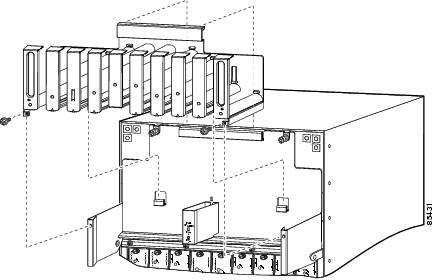
Step 4![]() Position the cable management assembly in front of the chassis, align the four screw holes in the attachment bracket with the corresponding screw holes in the chassis, and secure the cable management assembly in place with the four 6-32 screws. (See Figure 1-21.)
Position the cable management assembly in front of the chassis, align the four screw holes in the attachment bracket with the corresponding screw holes in the chassis, and secure the cable management assembly in place with the four 6-32 screws. (See Figure 1-21.)
Figure 1-21 Installing the Catalyst 6509-V-E Cable Management Assembly
|
|
|
||
|
|
|
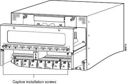
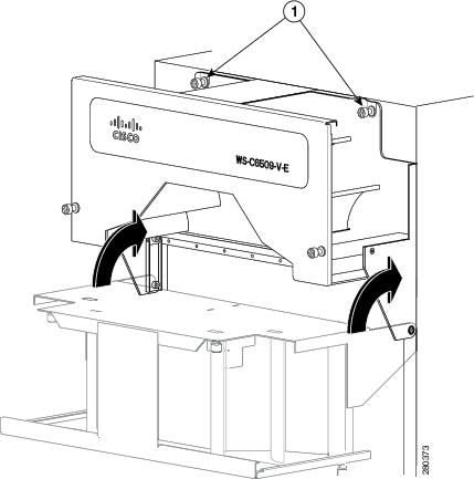
Step 5![]() Pivot the cable management assembly up on its hinges so that the back plate of the assembly is flush against the chassis. Secure the cable management assembly in place to the front of the chassis with the two captive installation screws. (See Figure 1-22.)
Pivot the cable management assembly up on its hinges so that the back plate of the assembly is flush against the chassis. Secure the cable management assembly in place to the front of the chassis with the two captive installation screws. (See Figure 1-22.)
Figure 1-22 Securing the Cable Management Assembly to the Front of the Chassis
|
|
|
What is Next
After installing the chassis in its location, complete the installation process by following these procedures:
- Connecting the chassis to system ground. See “Establishing the System Ground” section.
- Installing and connecting the power supplies to source power. Go to Chapter 4 for information on how to install and cable power supplies.
- Connecting the network interface cables to the supervisor engine and modules. This may involve installing transceivers before you attach the network interface cables. See “Attaching the Interface Cables” section.
Note![]() If you are going to use the cable management system to route the network interface cables, refer to “Using the Catalyst 6509-V-E Cable Management System” section.
If you are going to use the cable management system to route the network interface cables, refer to “Using the Catalyst 6509-V-E Cable Management System” section.
- Powering-up the chassis and verifying the installation. See “Verifying Switch Chassis Installation” section.
Optional Installation Kits
There are no optional installation kits for the Catalyst 6509-V-E switch chassis.
Installing a Catalyst 6513 or Catalyst 6513-E Switch Chassis
This section provides a procedure for installing either a Catalyst 6513 or Catalyst 6513-E switch chassis in a rack assembly and installing the optional cable guide assemblies.
Installation Accessory Kit
The Catalyst 6513 and the Catalyst 6513-E switch chassis are designed to be installed in a standard 19-inch rack either open or enclosed. The chassis is shipped with the 19-inch rack-mount brackets factory installed on the left-front and right-front of the chassis. Included in the accessory kit are 10-32 x 0.75-inch and 12-24 x 0.75-inch screws that are used to secure the chassis in the rack.
Note![]() Depending on the manufacturer, the rack posts might be prethreaded to accept either 10-32 or 12-24 screws. If the rack posts are not prethreaded, you must install 10-32 or 12-24 clip nuts or cage nuts to secure the rack-mount screws. The clip nuts or the cage nuts are not included as part of the accessory kit and must be obtained on your own.
Depending on the manufacturer, the rack posts might be prethreaded to accept either 10-32 or 12-24 screws. If the rack posts are not prethreaded, you must install 10-32 or 12-24 clip nuts or cage nuts to secure the rack-mount screws. The clip nuts or the cage nuts are not included as part of the accessory kit and must be obtained on your own.
The accessory kit also contains the following chassis installation kits:
- A rack-mount shelf kit. The rack-mount shelf kit is used to support the weight of the chassis while you secure the chassis L brackets to the rack enclosure.
- A stabilizer bracket kit. If you are not installing the Catalyst 6513 or Catalyst 6513-E switch in a rack, you must install the stabilizer brackets to the bottom of the chassis. The stabilizer brackets reduce the possibility that the freestanding switch chassis will tip over.
Also included in the accessory kit:
- Two optional cable guides—The two cable guides can be installed on the front left- and right-sides of the chassis using the same sets of screws (either 10-32 or 12-24) that secure the chassis rack-mount L brackets to the rack posts.
- Power supply blank panel—The power supply blank panel must be installed on an unused power supply bay to maintain chassis airflow and EMI shielding.
L Brackets on the Catalyst 6513 and Catalyst 6513-E Switch Chassis
The Catalyst 6513 and the Catalyst 6513-E switch chassis are shipped with the two L brackets installed on the front sides of the chassis. The L brackets are secured to the chassis with 14 M3 Phillips-head countersunk screws (seven screws on each side) as shown in Figure 1-23.
Note![]() The L brackets can also be reversed and installed on the rear of the chassis as an alternative method of installation.
The L brackets can also be reversed and installed on the rear of the chassis as an alternative method of installation.
Figure 1-23 L Brackets on the Catalyst 6513 Switch Chassis
|
|
|
Installing the 3 RU Rack-Mount Shelf Kit
The 3 RU rack-mount shelf kit is included as part of the accessory kit for the Catalyst 6513 and the Catalyst 6513-E switch chassis. You need to install this kit first before you install the chassis in the rack. The shelf kit supports the weight of the chassis while you install the chassis in the rack.
The procedure for installing the shelf kit is located in the “Installing the 3 RU Rack-Mount Shelf Kit” section.
Rack-Mounting the Chassis
Tip![]() We recommend that you have a third person to assist in this procedure.
We recommend that you have a third person to assist in this procedure.
Warning![]() Two people are required to lift the chassis. To prevent injury, keep your back straight and lift with your legs, not your back. Statement 164
Two people are required to lift the chassis. To prevent injury, keep your back straight and lift with your legs, not your back. Statement 164
To install the switch chassis in the equipment rack, follow these steps:
Step 1![]() With a person standing at each side of the chassis, grasp the chassis handle with one hand, and use the other hand near the back of the chassis for balance. Slowly lift the chassis in unison. Avoid sudden twists or moves to prevent injury.
With a person standing at each side of the chassis, grasp the chassis handle with one hand, and use the other hand near the back of the chassis for balance. Slowly lift the chassis in unison. Avoid sudden twists or moves to prevent injury.
Step 2![]() Position the chassis in the rack as follows:
Position the chassis in the rack as follows:
a.![]() If the front of the chassis (front panel) is at the front of the rack, insert the rear of the chassis between the mounting posts, resting the chassis on the shelf brackets, and then carefully slide the chassis into the rack.
If the front of the chassis (front panel) is at the front of the rack, insert the rear of the chassis between the mounting posts, resting the chassis on the shelf brackets, and then carefully slide the chassis into the rack.
b.![]() If the rear of the chassis is at the front of the rack, insert the front of the chassis between the mounting posts, resting the chassis on the shelf brackets, and then carefully slide the chassis into the rack.
If the rear of the chassis is at the front of the rack, insert the front of the chassis between the mounting posts, resting the chassis on the shelf brackets, and then carefully slide the chassis into the rack.
Step 3![]() Locate the rack post holes that align with the chassis L bracket holes. If the rack post holes are prethreaded, determine if the threads are 10-32 or 12-24. If the rack post holes are unthreaded, install eight or ten (four or five on each side) either 10-32 or 12-24 clip or cage nuts over the rack post holes to accept the installation screws.
Locate the rack post holes that align with the chassis L bracket holes. If the rack post holes are prethreaded, determine if the threads are 10-32 or 12-24. If the rack post holes are unthreaded, install eight or ten (four or five on each side) either 10-32 or 12-24 clip or cage nuts over the rack post holes to accept the installation screws.
Note![]() Clip nuts or cage nuts are not included as part of the accessory kit that comes with the chassis. You must obtain them yourself.
Clip nuts or cage nuts are not included as part of the accessory kit that comes with the chassis. You must obtain them yourself.
Step 4![]() If you want to install one or both of the optional cable guide assemblies, position the cable guides so that the cable guide mounting holes are aligned with rack-mount bracket holes and the rack post holes as shown in Figure 1-24.
If you want to install one or both of the optional cable guide assemblies, position the cable guides so that the cable guide mounting holes are aligned with rack-mount bracket holes and the rack post holes as shown in Figure 1-24.
Step 5![]() Install a minimum of ten (five on each side) 10-32 or 12-24 screws through the cable guide mounting holes, rack-mount L bracket holes, rack post holes, and into the clip nuts to secure the cable guides and the chassis to the rack post. Tighten the screws securely. (See Figure 1-24.)
Install a minimum of ten (five on each side) 10-32 or 12-24 screws through the cable guide mounting holes, rack-mount L bracket holes, rack post holes, and into the clip nuts to secure the cable guides and the chassis to the rack post. Tighten the screws securely. (See Figure 1-24.)
Step 6![]() Use a tape measure and level to verify that the chassis is installed straight and level.
Use a tape measure and level to verify that the chassis is installed straight and level.
Note![]() If you are not rack-mounting the Catalyst 6513 or the Catalyst 6513-E switch and you are installing the optional cable guide assemblies, you must obtain ten 12-24 or 10-32 nuts. Use the screws supplied in the accessory kit and the nuts you obtained to attach the cable guide assembly to the L bracket.
If you are not rack-mounting the Catalyst 6513 or the Catalyst 6513-E switch and you are installing the optional cable guide assemblies, you must obtain ten 12-24 or 10-32 nuts. Use the screws supplied in the accessory kit and the nuts you obtained to attach the cable guide assembly to the L bracket.
Figure 1-24 Installing the Catalyst 6513 Switch Chassis in the Rack
What is Next
After installing the chassis in its location, complete the installation process by following these procedures:
- Connecting the chassis to system ground. See “Establishing the System Ground” section.
- Installing and connecting the power supplies to source power. Go to Chapter 4 for information on how to install and cable power supplies.
- Connecting the network interface cables to the supervisor engine and modules. This may involve installing transceivers before you attach the network interface cables. See “Attaching the Interface Cables” section.
- Powering-up the chassis and verifying the installation. See “Verifying Switch Chassis Installation” section.
Optional Installation Kits
An optional stabilizer bracket installation kit is included in the accessory kit for the Catalyst 6513 and the Catalyst 6513-E switch chassis. This kit contains the parts necessary to install two brackets on the bottom of the chassis to provide additional stability for the chassis when the chassis is not rack mounted allowing the chassis to placed on a shelf or a table. To install the stabilizer brackets, go to “Installing the Stabilizer Bracket Kit” section
A center rack-mount kit for 23-inch, telco-style racks is available as an option for the Catalyst 6513 and the Catalyst 6513-E switch chassis. The center rack-mount kit is not included in the accessory kit, but is available as a separately orderable item (p/n WS-6513-RACK-MNT=). Installation instructions are included with the kit.
Generic Installation Procedures
This section provides procedures covering how to install three installation kits that are included in multiple Catalyst 6500 series chassis accessory kits. The following procedures are provided in this section:
- Installing the 3 RU Rack-Mount Shelf Kit
- Installing the Rubber Feet Kit
- Installing the Stabilizer Bracket Kit
Installing the 3 RU Rack-Mount Shelf Kit
This section describes how to install the 3 RU rack-mount shelf kit. The kit contains shelf brackets, a crossbar bracket, and screws. The shelf brackets attach directly to the rack and help support the weight of the chassis while you secure the L brackets to the rack enclosure. The rack-mount shelf kit is shipped as part of the Catalyst 6500 series switch accessory kit with the following chassis:
- Catalyst 6506 and Catalyst 6506-E
- Catalyst 6509 and Catalyst 6509-E
- Catalyst 6509-NEB and Catalyst 6509-NEB-A
- Catalyst 6509-V-E
- Catalyst 6513 and Catalyst 6513-E
Table 1-3 lists and describes the contents of the rack-mount shelf kit.
Note![]() This rack-mounting kit is not suitable for use with racks that have obstructions (such as power strips) because the obstructions could impair access to switch field-replaceable units (FRUs).
This rack-mounting kit is not suitable for use with racks that have obstructions (such as power strips) because the obstructions could impair access to switch field-replaceable units (FRUs).
Required Tools
These tools and equipment are required to install the rack-mount shelf kit:
Installing the Shelf Brackets and Crossbar Bracket
Note![]() On many older equipment racks, the rack posts are prethreaded to accept either 10-32 or 12-24 screws. Newer rack enclosure posts might not be prethreaded. These rack enclosure posts require that you install 10-32 or 12-24 clip nuts or cage nuts to secure the rack-mount screws. The clip nuts or the cage nuts are not included as part of the accessory kit and must be obtained on your own.
On many older equipment racks, the rack posts are prethreaded to accept either 10-32 or 12-24 screws. Newer rack enclosure posts might not be prethreaded. These rack enclosure posts require that you install 10-32 or 12-24 clip nuts or cage nuts to secure the rack-mount screws. The clip nuts or the cage nuts are not included as part of the accessory kit and must be obtained on your own.
To install the shelf bracket and crossbar bracket, follow these steps:
Step 1![]() Position one of the two shelf brackets in the rack as shown in Figure 1-25.
Position one of the two shelf brackets in the rack as shown in Figure 1-25.
Step 2![]() Secure the shelf bracket to the rack by using three 12-24 x 3/4-inch or 10-32 x 3/4-inch screws.
Secure the shelf bracket to the rack by using three 12-24 x 3/4-inch or 10-32 x 3/4-inch screws.
Step 3![]() Repeat Steps 1 and 2 for the second shelf bracket. Make sure that the second shelf bracket is level with the first bracket.
Repeat Steps 1 and 2 for the second shelf bracket. Make sure that the second shelf bracket is level with the first bracket.
Step 4![]() Attach the crossbar bracket to the back of the shelf brackets using two M3 screws as shown in Figure 1-26.
Attach the crossbar bracket to the back of the shelf brackets using two M3 screws as shown in Figure 1-26.
Figure 1-25 Installing the Shelf Brackets
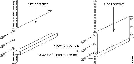
Figure 1-26 Attaching the Crossbar Bracket to the Shelf Brackets
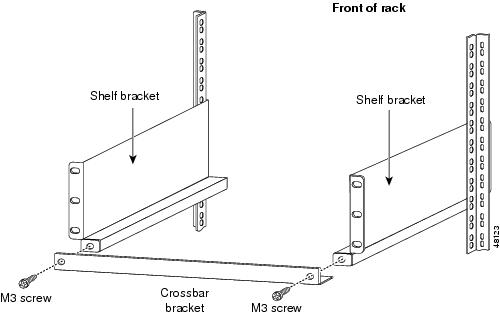
Installing the Rubber Feet Kit
This section describes how to install the rubber feet kit. The kit contains four rubber feet and mounting screws. The rubber feet attach directly to the bottom of the chassis and support the weight of the chassis. The rubber feet kit is shipped as part of the Catalyst 6500 series switch accessory kit with the following chassis:
To install the rubber feet kit, perform the following steps:
Step 1![]() Tilt the chassis to one side to access the bottom of the chassis.
Tilt the chassis to one side to access the bottom of the chassis.
Step 2![]() Position one of the rubber feet over the threaded hole on the bottom corner of the chassis.
Position one of the rubber feet over the threaded hole on the bottom corner of the chassis.
Step 3![]() Secure the rubber foot to the chassis with one of the M5 x 12 mm Phillips screws provided in the installation kit.
Secure the rubber foot to the chassis with one of the M5 x 12 mm Phillips screws provided in the installation kit.
Step 4![]() Repeat step 1 through step 3 to install the remaining three rubber feet in the bottom corners of the chassis.
Repeat step 1 through step 3 to install the remaining three rubber feet in the bottom corners of the chassis.
Step 5![]() Position the chassis upright so that it rests on the four rubber feet.
Position the chassis upright so that it rests on the four rubber feet.
Installing the Stabilizer Bracket Kit
The stabilizer bracket kit is included as part of the accessory kits for the following chassis:
If you are not installing the Catalyst 6509-NEB, Catalyst 6513, or Catalyst 6513-E switch in a rack, you must install stabilizer brackets to the bottom of the chassis. The stabilizer brackets reduce the possibility that the freestanding switch chassis will tip over.
Table 1-4 lists and describes the contents of the rack-mount shelf kit.
|
|
|
|---|---|
M4 Phillips-head countersunk screws used to secure the stabilizer brackets to the chassis |
|
Note![]() You will need the assistance of a second person to perform this installation.
You will need the assistance of a second person to perform this installation.
To install the stabilizer brackets, follow these steps:
Step 1![]() Have one person tilt and hold the chassis to one side.
Have one person tilt and hold the chassis to one side.
Step 2![]() With the chassis slightly tilted, attach the stabilizer bracket to the side of the chassis with the eight M4 screws, as shown in Figure 1-27.
With the chassis slightly tilted, attach the stabilizer bracket to the side of the chassis with the eight M4 screws, as shown in Figure 1-27.
Step 3![]() Tilt the chassis to the other side.
Tilt the chassis to the other side.
Step 4![]() Attach the second stabilizer bracket to the other side of the chassis with eight M4 screws.
Attach the second stabilizer bracket to the other side of the chassis with eight M4 screws.
Step 5![]() Lower the chassis so that it rests on both stabilizer brackets.
Lower the chassis so that it rests on both stabilizer brackets.
Figure 1-27 Installing the Stabilizer Brackets
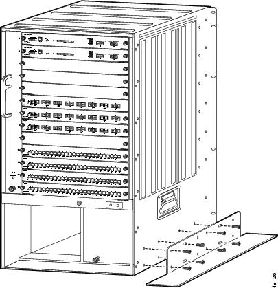
Note![]() If you are not rack-mounting the Catalyst 6513 or the Catalyst 6513-E switch chassis and you want to install the optional cable guide assemblies, you must obtain ten 12-24 or 10-32 nuts. Use the screws supplied in the accessory kit and the nuts you obtained to attach the cable guide assembly to the L bracket.
If you are not rack-mounting the Catalyst 6513 or the Catalyst 6513-E switch chassis and you want to install the optional cable guide assemblies, you must obtain ten 12-24 or 10-32 nuts. Use the screws supplied in the accessory kit and the nuts you obtained to attach the cable guide assembly to the L bracket.
Establishing the System Ground
This section describes how to connect a system ground to the Catalyst 6500 series switches.
Note![]() This system ground is also referred to as the network equipment building system (NEBS) ground.
This system ground is also referred to as the network equipment building system (NEBS) ground.
The system (NEBS) ground provides additional grounding for EMI shielding requirements and grounding for the low voltage supplies (DC-DC converters) on the modules and is intended to satisfy the Telcordia Technologies NEBS requirements for supplemental bonding and grounding connections. You must observe the following system grounding guidelines for your chassis:
- You must install the system (NEBS) ground connection with any other rack or system power ground connections that you make. The system (NEBS) ground connection is required if FXS modules are installed or if this equipment is installed in a U.S. or European Central Office.
- You must connect both the system (NEBS) ground connection and the power supply ground connection to an earth ground. The system (NEBS) ground connection is required if FXS modules are installed or if this equipment is installed in a U.S. or European Central Office.
- For Catalyst 6503 or Catalyst 6503-E chassis that are equipped with DC-input power supplies, you must install the system (NEBS) ground before you attach the source DC power cables to the DC PEM. If the Catalyst 6503 or Catalyst 6503-E chassis is powered up, you must power down the chassis before attaching the system (NEBS) ground. If you are installing the system (NEBS) ground on other models of the Catalyst 6500 series chassis that are equipped with either AC-input or DC-input power supplies, you do not need to power down the chassis.
- If you are installing the 8700 W AC-input power supply on a Catalyst 6506, Catalyst 6509, or on a Catalyst 6509-NEB chassis, you must install the system ground (NEBS ground) on the power supply rather than on the switch chassis. The extended depth of the 8700 W power supply blocks access to the system ground pad on those chassis. There are two ground posts located on the power supply faceplate where the system ground connection can be made.
Note![]() In all situations, grounding practices must comply with Section 250 of the National Electric Code (NEC) requirements or local laws and regulations. A 6 AWG grounding wire is preferred from the chassis to the rack ground or directly to the common bonding network (CBN). The equipment rack should also be connected to the CBN with 6 AWG grounding wire.
In all situations, grounding practices must comply with Section 250 of the National Electric Code (NEC) requirements or local laws and regulations. A 6 AWG grounding wire is preferred from the chassis to the rack ground or directly to the common bonding network (CBN). The equipment rack should also be connected to the CBN with 6 AWG grounding wire.
Note![]() The system (NEBS) ground serves as the primary safety ground for the Catalyst 6503 and Catalyst 6503-E chassis that are equipped with DC-input power supplies. The DC-input power supplies for these chassis do not have a separate ground.
The system (NEBS) ground serves as the primary safety ground for the Catalyst 6503 and Catalyst 6503-E chassis that are equipped with DC-input power supplies. The DC-input power supplies for these chassis do not have a separate ground.
Required Tools and Equipment
To connect the system ground, you need the following tools and materials:
- Grounding lug—A two-hole standard barrel lug. Supports up to 6 AWG wire. Supplied as part of accessory kit.
- Grounding screws—Two M4 x 8 mm (metric) pan-head screws. Supplied as part of the accessory kit.
- Grounding wire—Not supplied as part of accessory kit. The grounding wire should be sized according to local and national installation requirements. Depending on the power supply and system, a 12 AWG to 6 AWG copper conductor is required for U.S. installations. Commercially available 6 AWG wire is recommended. The length of the grounding wire depends on the proximity of the switch to proper grounding facilities.
- No. 1 Phillips screwdriver.
- Crimping tool to crimp the grounding wire to the grounding lug.
- Wire-stripping tool to remove the insulation from the grounding wire.
Connecting the System Ground
To attach the grounding lug and cable to the grounding pad, follow these steps:
Step 1![]() Use a wire-stripping tool to remove approximately 0.75 inch (19 mm) of the covering from the end of the grounding wire.
Use a wire-stripping tool to remove approximately 0.75 inch (19 mm) of the covering from the end of the grounding wire.
Step 2![]() Insert the stripped end of the grounding wire into the open end of the grounding lug.
Insert the stripped end of the grounding wire into the open end of the grounding lug.
Step 3![]() Crimp the grounding wire in the barrel of the grounding lug. Verify that the ground wire is securely attached to the ground lug.
Crimp the grounding wire in the barrel of the grounding lug. Verify that the ground wire is securely attached to the ground lug.
Step 4![]() Locate and remove the adhesive label from the system grounding pad on the switch. The location of the system grounding pad differs among Catalyst 6500 series chassis.
Locate and remove the adhesive label from the system grounding pad on the switch. The location of the system grounding pad differs among Catalyst 6500 series chassis.
Refer to these figures to locate the system grounding pad on your chassis:
- Catalyst 6503 and Catalyst 6503-E chassis—Figure 1-28
- Catalyst 6504-E chassis—Figure 1-29
- Catalyst 6506, Catalyst 6509, and Catalyst 6509-NEB chassis—Figure 1-30
- Catalyst 6506-E, Catalyst 6509-E, Catalyst 6513, and Catalyst 6513-E chassis—Figure 1-31
- Catalyst 6509-NEB-A and Catalyst 6509-V-E chassis—Figure 1-32
Step 5![]() Place the grounding wire lug against the grounding pad, making sure that there is solid metal-to-metal contact.
Place the grounding wire lug against the grounding pad, making sure that there is solid metal-to-metal contact.
Note![]() There are two system grounding pads on the Catalyst 6509-NEB-A and the Catalyst 6509-V-E switch chassis. One pad is located in the upper-left corner of the chassis, and the other is located in the upper-right corner of the chassis. Additionally, both system grounding pads have 3 M4 screw holes so that the system grounding lug can be installed either horizontally or vertically.
There are two system grounding pads on the Catalyst 6509-NEB-A and the Catalyst 6509-V-E switch chassis. One pad is located in the upper-left corner of the chassis, and the other is located in the upper-right corner of the chassis. Additionally, both system grounding pads have 3 M4 screw holes so that the system grounding lug can be installed either horizontally or vertically.
Step 6![]() Secure the grounding lug to the chassis with two M4 screws. Ensure that the grounding lug and the grounding wire will not interfere with other switch hardware or rack equipment.
Secure the grounding lug to the chassis with two M4 screws. Ensure that the grounding lug and the grounding wire will not interfere with other switch hardware or rack equipment.
Step 7![]() Prepare the other end of the grounding wire, and connect it to an appropriate grounding point in your site to ensure adequate earth ground for the switch.
Prepare the other end of the grounding wire, and connect it to an appropriate grounding point in your site to ensure adequate earth ground for the switch.
Figure 1-28 System Ground Location (Catalyst 6503 and Catalyst 6503-E Chassis)
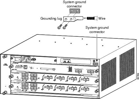
Figure 1-29 System Ground Location (Catalyst 6504-E Chassis)
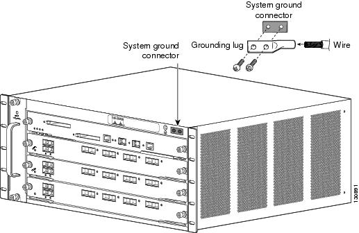
Figure 1-30 System Ground Location (Catalyst 6506, Catalyst 6509, and Catalyst 6509-NEB Chassis)
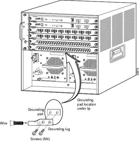
Figure 1-31 System Ground Location (Catalyst 6506-E, Catalyst 6509-E, Catalyst 6513, and Catalyst 6513-E Chassis)
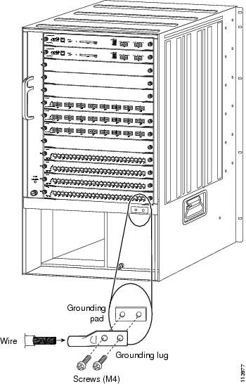
Figure 1-32 System Ground Location (Catalyst 6509-NEB-A and Catalyst 6509-V-E)
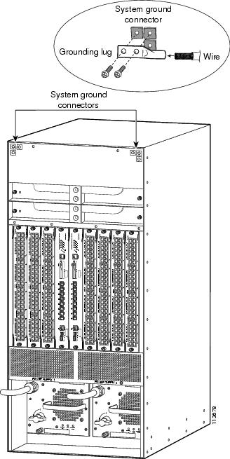
Installing the System Ground on an 8700 W Power Supply
If you have a Catalyst 6506, Catalyst 6509, or Catalyst 6509-NEB chassis with an 8700 W power supply installed, you must attach the system ground lug to the two system ground studs on the power supply faceplate. The extended depth of the 8700 W power supply blocks access to the system ground pad on the switch chassis.
To attach the system ground lug and cable to the power supply ground studs, follow these steps:
Step 1![]() Use a wire-stripping tool to remove approximately 0.75 inch (19 mm) of the covering from the end of the grounding wire.
Use a wire-stripping tool to remove approximately 0.75 inch (19 mm) of the covering from the end of the grounding wire.
Step 2![]() Insert the stripped end of the grounding wire into the open end of the grounding lug.
Insert the stripped end of the grounding wire into the open end of the grounding lug.
Step 3![]() Crimp the grounding wire in the barrel of the grounding lug. Verify that the ground wire is securely attached to the ground lug.
Crimp the grounding wire in the barrel of the grounding lug. Verify that the ground wire is securely attached to the ground lug.
Step 4![]() Remove the M4 nuts, split-ring washers, flat washers from the two system ground studs on the power supply.
Remove the M4 nuts, split-ring washers, flat washers from the two system ground studs on the power supply.
Step 5![]() Position the grounding lug over the two system ground studs on the 8700 W power supply faceplate. (See Figure 1-33.) Ensure that the grounding lug and the grounding wire will not interfere with other switch hardware or rack equipment.
Position the grounding lug over the two system ground studs on the 8700 W power supply faceplate. (See Figure 1-33.) Ensure that the grounding lug and the grounding wire will not interfere with other switch hardware or rack equipment.
Step 6![]() Install one flat washer and one split-ring washer over each system ground stud. Secure the system grounding lug and washers in place with the two M4 nuts.
Install one flat washer and one split-ring washer over each system ground stud. Secure the system grounding lug and washers in place with the two M4 nuts.
Step 7![]() Prepare the other end of the grounding wire, and connect it to an appropriate grounding point in your site to ensure adequate earth ground for the switch.
Prepare the other end of the grounding wire, and connect it to an appropriate grounding point in your site to ensure adequate earth ground for the switch.
Figure 1-33 Installing the System Ground Lug on the 8700 W Power Supply
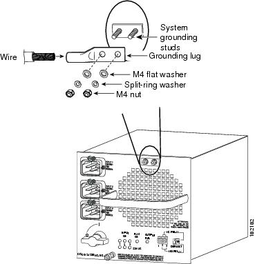
Installing the Power Supplies in the Switch Chassis
The chassis secondary power supplies (AC or DC) are shipped separately from the switch chassis. Remove the power supply from its shipping packaging, and then install and connect it to the site power by referring to the “Removing and Installing the AC-Input Power Supplies” section or the “Removing and Installing the DC-Input Power Supplies” section. Verify that you have the correct power supply (AC-input or DC-input and the correct wattage) for your configuration.
Note![]() AC-input and DC-input power supplies can be mixed in a chassis.
AC-input and DC-input power supplies can be mixed in a chassis.
Attaching the Interface Cables
This section provides general information on attaching interface cables to the supervisor engines and to the modules.
Note![]() Refer to the Catalyst 6500 Series Switch Module Guide for additional module information.
Refer to the Catalyst 6500 Series Switch Module Guide for additional module information.
Connecting the Supervisor Engine Console Port
This section describes how to connect to the supervisor engine console port from a terminal or modem.
The console port on the supervisor engine allows you to perform the following functions:
- Configure the switch from the CLI.
- Monitor network statistics and errors.
- Configure SNMP agent parameters.
- Download software updates to the switch, or distribute software images residing in flash memory to attached devices.
The console port, located on the front panel of the supervisor engine, is shown in Figure 1-34.
Figure 1-34 Supervisor Engine Console Port Connector
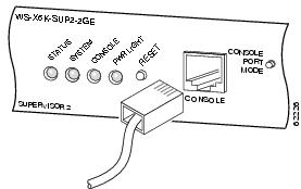
Note![]() The accessory kit that shipped with your Catalyst 6500 series switch contains the necessary cable and adapters to connect a terminal or modem to the console port.
The accessory kit that shipped with your Catalyst 6500 series switch contains the necessary cable and adapters to connect a terminal or modem to the console port.
To connect a terminal to the console port using the cable and adapters provided, follow these steps:
Step 1![]() Place the console port mode switch in the in position (factory default).
Place the console port mode switch in the in position (factory default).
Step 2![]() Connect to the port using the RJ-45-to-RJ-45 cable and RJ-45-to-DB-25 DTE adapter or RJ-45-to-DB-9 DTE adapter (labeled “Terminal”).
Connect to the port using the RJ-45-to-RJ-45 cable and RJ-45-to-DB-25 DTE adapter or RJ-45-to-DB-9 DTE adapter (labeled “Terminal”).
Step 3![]() Position the cable in the cable guide (if installed). Make sure there are no sharp bends in the cable.
Position the cable in the cable guide (if installed). Make sure there are no sharp bends in the cable.
Step 4![]() Check the terminal documentation to determine the baud rate. The baud rate of the terminal must match the default baud rate (9600 baud) of the console port. Set up the terminal as follows:
Check the terminal documentation to determine the baud rate. The baud rate of the terminal must match the default baud rate (9600 baud) of the console port. Set up the terminal as follows:
To connect a terminal using a Catalyst 5000 family Supervisor Engine III console cable, follow these steps:
Step 1![]() Place the console port mode switch in the out position.
Place the console port mode switch in the out position.
Step 2![]() Connect to the port using the Supervisor Engine III cable and the appropriate adapter for the terminal connection.
Connect to the port using the Supervisor Engine III cable and the appropriate adapter for the terminal connection.
Step 3![]() Position the cable in the cable guide (if installed). Make sure there are no sharp bends in the cable.
Position the cable in the cable guide (if installed). Make sure there are no sharp bends in the cable.
Step 4![]() Check the terminal documentation to determine the baud rate. The baud rate of the terminal must match the default baud rate (9600 baud) of the console port. Set up the terminal as follows:
Check the terminal documentation to determine the baud rate. The baud rate of the terminal must match the default baud rate (9600 baud) of the console port. Set up the terminal as follows:
To connect a modem to the console port, follow these steps:
Step 1![]() Place the console port mode switch in the in position.
Place the console port mode switch in the in position.
Step 2![]() Connect to the port using the RJ-45-to-RJ-45 rollover cable and the RJ-45-to-DB-25 DCE adapter (labeled “Modem”).
Connect to the port using the RJ-45-to-RJ-45 rollover cable and the RJ-45-to-DB-25 DCE adapter (labeled “Modem”).
Step 3![]() Position the cable in the cable guide (if installed). Make sure there are no sharp bends in the cable.
Position the cable in the cable guide (if installed). Make sure there are no sharp bends in the cable.
Connecting the Supervisor Engine Uplink Ports
This section describes how to connect to the supervisor engine uplink ports. Refer to Table 1-5 for information on which uplink ports each type of supervisor engine has.
Warning![]() Invisible laser radiation may be emitted from disconnected fibers or connectors. Do not stare into beams or view directly with optical instruments. Statement 1051
Invisible laser radiation may be emitted from disconnected fibers or connectors. Do not stare into beams or view directly with optical instruments. Statement 1051
Warning![]() Class 1 laser product. Statement 1008
Class 1 laser product. Statement 1008
Note![]() In a redundant configuration with two supervisor engines, the uplink ports on the redundant (standby) supervisor engine are active and can be used for normal traffic like any other ports in the chassis.
In a redundant configuration with two supervisor engines, the uplink ports on the redundant (standby) supervisor engine are active and can be used for normal traffic like any other ports in the chassis.
|
|
|
|
|---|---|---|
Two uplink ports. Both ports require that GBIC transceivers be installed. |
“Installing and Cabling GBIC Transceiver Uplink Ports” section |
|
WS-SUP32-GE-3B—Nine uplink ports. Eight ports require that 1000BASE-X SFP transceivers be installed. One port is a 10/100/1000 port with an RJ-45 connector. WS-SUP32-10GE-3B—Three uplink ports. Two ports require that 10GBASE XENPAK transceivers be installed. One port is a 10/100/1000 port with an RJ-45 connector. |
“Installing and Cabling Optical SFP Transceiver Uplink Ports” section “Installing and Cabling Copper SFP Transceiver Uplink Ports” section “Installing and Cabling 10GBASE-X XENPAK Transceiver Uplink Ports” section |
|
WS-S32-GE-PISA—Nine uplink ports. Eight ports require that 1000BASE-X SFP transceivers be installed. One port is a 10/100/1000 port with an RJ-45 connector. WS-S32-10GE-PISA—Three uplink ports. Two ports require that 10GBASE XENPAK transceivers be installed. One port is a 10/100/1000 port with an RJ-45 connector. |
“Installing and Cabling Optical SFP Transceiver Uplink Ports” section “Installing and Cabling Copper SFP Transceiver Uplink Ports” section “Installing and Cabling 10GBASE-X XENPAK Transceiver Uplink Ports” section |
|
Three uplink ports. Two ports require 1000BASE-X GBIC transceivers be installed. One port is a 10/100/1000 port with an RJ-45 connector. |
“Installing and Cabling GBIC Transceiver Uplink Ports” section |
|
Five uplink ports. Two ports require SFP transceivers be installed. One port is a 10/100/1000 port with an RJ-45 connector. Two ports require that 10GBASE X2 transceivers be installed. |
“Installing and Cabling Optical SFP Transceiver Uplink Ports” section “Installing and Cabling Copper SFP Transceiver Uplink Ports” section “Installing and Cabling 10GBASE-X X2 Transceiver Uplink Ports” section |
Installing and Cabling GBIC Transceiver Uplink Ports
To install and cable an GBIC transceiver uplink port, follow these steps (see Figure 1-35):
Step 1![]() Attach an ESD-preventive wrist strap to your wrist and to the ESD ground connector or a bare metal surface on your chassis.
Attach an ESD-preventive wrist strap to your wrist and to the ESD ground connector or a bare metal surface on your chassis.
Step 2![]() Remove the GBIC transceiver from its protective packaging.
Remove the GBIC transceiver from its protective packaging.
Note![]() Do not remove the optical bore dust plugs until you are directed to do so later in the procedure.
Do not remove the optical bore dust plugs until you are directed to do so later in the procedure.
Step 3![]() Check the label on the GBIC transceiver body to verify that you have the correct model for your network.
Check the label on the GBIC transceiver body to verify that you have the correct model for your network.
Step 4![]() Find the transmit (TX) and receive (RX) markings that identify the top side of the GBIC transceiver.
Find the transmit (TX) and receive (RX) markings that identify the top side of the GBIC transceiver.
Note![]() On some GBIC transceivers, the TX and RX marking might be replaced by arrowheads pointing from the GBIC transceiver connector (transmit direction or TX) and toward the connector (receive direction or RX).
On some GBIC transceivers, the TX and RX marking might be replaced by arrowheads pointing from the GBIC transceiver connector (transmit direction or TX) and toward the connector (receive direction or RX).
Step 5![]() Position the GBIC transceiver in front of the socket opening and insert the GBIC transceiver into the socket until you feel the GBIC transceiver module connector snap into place in the socket connector.
Position the GBIC transceiver in front of the socket opening and insert the GBIC transceiver into the socket until you feel the GBIC transceiver module connector snap into place in the socket connector.
Note For optical GBIC transceivers, before removing the dust plugs and making any optical connections, observe the following guidelines:
- Always keep the protective dust plugs on the unplugged fiber-optic cable connectors and the transceiver optical bores until you are ready to make a connection.
- Always inspect and clean the SC connector end-faces just before making any connections.
- Always grasp the SC connector housing to plug or unplug a fiber-optic cable.
Step 6![]() Remove the dust plugs from the network interface cable SC connectors. Save the dust plugs for future use.
Remove the dust plugs from the network interface cable SC connectors. Save the dust plugs for future use.
Step 7![]() Inspect and clean the SC connector’s fiber-optic end-faces. (Refer to “Cleaning the Fiber-Optic Connectors” section.)
Inspect and clean the SC connector’s fiber-optic end-faces. (Refer to “Cleaning the Fiber-Optic Connectors” section.)
Step 8![]() Remove the dust plugs from the GBIC transceiver optical bores.
Remove the dust plugs from the GBIC transceiver optical bores.
Step 9![]() Immediately attach the network interface cable SC connector to the GBIC transceiver.
Immediately attach the network interface cable SC connector to the GBIC transceiver.
Step 10![]() To connect 1000BASE-T GBIC transceivers to a copper network, perform the following substeps:
To connect 1000BASE-T GBIC transceivers to a copper network, perform the following substeps:
a.![]() Insert the Category 5 network cable RJ-45 connector into the GBIC transceiver.
Insert the Category 5 network cable RJ-45 connector into the GBIC transceiver.
Note![]() When connecting to a 1000BASE-T-compatible server, workstation, or router, use four twisted-pair, straight-through Category 5 cabling for the GBIC transceiver port. When connecting to a 1000BASE-T-compatible switch or repeater, use four twisted-pair, crossover Category 5 cabling.
When connecting to a 1000BASE-T-compatible server, workstation, or router, use four twisted-pair, straight-through Category 5 cabling for the GBIC transceiver port. When connecting to a 1000BASE-T-compatible switch or repeater, use four twisted-pair, crossover Category 5 cabling.
b.![]() Insert the other end of the network cable into an RJ-45 port on a 1000BASE-T-compatible target device.
Insert the other end of the network cable into an RJ-45 port on a 1000BASE-T-compatible target device.
Step 11![]() Observe the port status LED:
Observe the port status LED:
- The LED turns green when the GBIC transceiver and the target device have an established link.
- The LED turns amber while the GBIC discovers the network topology and searches for loops. This process takes about 30 seconds, and then the LED turns green.
- If the LED is off, the target device might not be turned on, there might be a cable problem, or there might be a problem with the adapter that is installed in the target device.
Figure 1-35 Connecting the Supervisor Engine Uplink Ports
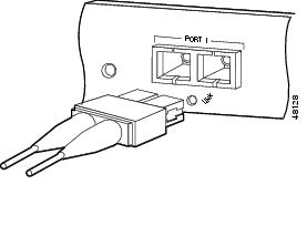
Note![]() If you are using the LX/LH GBIC with MMF, you need to install a patch cord between the GBIC and the MMF cable.
If you are using the LX/LH GBIC with MMF, you need to install a patch cord between the GBIC and the MMF cable.
Installing and Cabling Optical SFP Transceiver Uplink Ports
To install and cable an optical SFP transceiver uplink port, follow these steps:
Step 1![]() Attach an ESD-preventive wrist strap to your wrist and to the ESD ground connector on the chassis or to a properly grounded bare metal surface.
Attach an ESD-preventive wrist strap to your wrist and to the ESD ground connector on the chassis or to a properly grounded bare metal surface.
Step 2![]() Remove the optical SFP transceiver module from its protective packaging.
Remove the optical SFP transceiver module from its protective packaging.
Note![]() Do not remove the optical bore dust plugs until you are directed to do so later in the procedure.
Do not remove the optical bore dust plugs until you are directed to do so later in the procedure.
Step 3![]() Check the label on the SFP transceiver body to verify that you have the correct model for your network.
Check the label on the SFP transceiver body to verify that you have the correct model for your network.
Step 4![]() Find the transmit (TX) and receive (RX) markings that identify the top side of the SFP transceiver.
Find the transmit (TX) and receive (RX) markings that identify the top side of the SFP transceiver.
Note![]() On some SFP transceivers, the TX and RX marking might be replaced by arrowheads pointing from the SFP transceiver connector (transmit direction or TX) and toward the connector (receive direction or RX).
On some SFP transceivers, the TX and RX marking might be replaced by arrowheads pointing from the SFP transceiver connector (transmit direction or TX) and toward the connector (receive direction or RX).
Step 5![]() Position the SFP transceiver in front of the socket opening. (See Figure 1-36.)
Position the SFP transceiver in front of the socket opening. (See Figure 1-36.)
Note![]() Different Cisco devices have different SFP module socket configurations. Your Cisco device could have either a latch-up or a latch-down orientation. Ensure that you are installing the SFP transceiver in the correct orientation for your Cisco device. For more details, refer to the hardware installation instructions that shipped along with your Cisco device.
Different Cisco devices have different SFP module socket configurations. Your Cisco device could have either a latch-up or a latch-down orientation. Ensure that you are installing the SFP transceiver in the correct orientation for your Cisco device. For more details, refer to the hardware installation instructions that shipped along with your Cisco device.
Step 6![]() Leave the bale-clasp in the closed (locked) position and slide the SFP transceiver into the socket until you feel the SFP transceiver snap into place in the socket. An audible click might also be heard as the SFP transceiver latch engages in the socket. (See Figure 1-39.)
Leave the bale-clasp in the closed (locked) position and slide the SFP transceiver into the socket until you feel the SFP transceiver snap into place in the socket. An audible click might also be heard as the SFP transceiver latch engages in the socket. (See Figure 1-39.)
Figure 1-36 Supervisor Engine 720 SFP Uplink Port
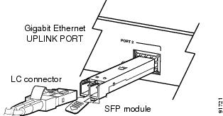
Note Before removing the dust plugs and making any optical connections, observe the following guidelines:
- Always keep the protective dust plugs on the unplugged fiber-optic cable connectors and the transceiver optical bores until you are ready to make a connection.
- Always inspect and clean the LC connector end-faces just before making any connections.
- Always grasp the LC connector housing to plug or unplug a fiber-optic cable.
Step 7![]() Remove the dust plugs from the network interface cable LC connectors. Save the dust plugs for future use.
Remove the dust plugs from the network interface cable LC connectors. Save the dust plugs for future use.
Step 8![]() Inspect and clean the LC connector’s fiber-optic end-faces. (Refer to the Tip below for a pointer to more information about fiber-optic inspection and cleaning.)
Inspect and clean the LC connector’s fiber-optic end-faces. (Refer to the Tip below for a pointer to more information about fiber-optic inspection and cleaning.)
Step 9![]() Remove the dust plugs from the SFP transceiver optical bores. Inspect and clean the LC connector’s fiber-optic end faces. (Refer to “Cleaning the Fiber-Optic Connectors” section.)
Remove the dust plugs from the SFP transceiver optical bores. Inspect and clean the LC connector’s fiber-optic end faces. (Refer to “Cleaning the Fiber-Optic Connectors” section.)
Step 10![]() Immediately attach the network interface cable LC connector to the SFP transceiver.
Immediately attach the network interface cable LC connector to the SFP transceiver.
Installing and Cabling Copper SFP Transceiver Uplink Ports
The copper SFP transceiver, see Figure 1-37, has a bale-clasp locking mechanism that secures the transceiver in the module socket. An RJ-45 connector provides the transceiver’s interface point to the network.
Figure 1-37 SFP Transceiver (Copper)
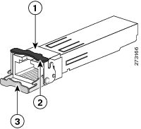
|
|
|
Bale-clasp latching mechanism shown in the open (unlocked) position |
|
|
|
Bale-clasp latching mechanism shown in the closed (locked) position |
|
Note![]() When connecting to a 1000BASE-T-compatible server, workstation, or router, use four twisted-pair, straight-through Category 5 cabling for the SFP transceiver port. When connecting to a 1000BASE-T-compatible switch or repeater, use four twisted-pair, crossover Category 5 cabling.
When connecting to a 1000BASE-T-compatible server, workstation, or router, use four twisted-pair, straight-through Category 5 cabling for the SFP transceiver port. When connecting to a 1000BASE-T-compatible switch or repeater, use four twisted-pair, crossover Category 5 cabling.
To install a copper SFP transceiver, follow these steps:
Step 1![]() Attach an ESD-preventive wrist strap to your wrist and to the ESD ground connector on the chassis or to a properly grounded bare metal surface.
Attach an ESD-preventive wrist strap to your wrist and to the ESD ground connector on the chassis or to a properly grounded bare metal surface.
Step 2![]() Remove the new copper SFP from its protective packaging.
Remove the new copper SFP from its protective packaging.
Step 3![]() Check the markings on the SFP transceiver to verify that you have the correct model for your network.
Check the markings on the SFP transceiver to verify that you have the correct model for your network.
Step 4![]() Position the SFP transceiver in front of the port socket opening.
Position the SFP transceiver in front of the port socket opening.
Note![]() Different Cisco devices have different SFP transceiver socket configurations. Your Cisco device might require that the SFP transceiver be installed with the bale-clasp either in a latch-up or a latch-down orientation. Figure 1-38, left view, shows the SFP installed in a latch-up orientation where the bale-clasp latching mechanism pivots up to the closed (locked) position. Figure 1-38, right view shows the SFP installed in a latch-down orientation where the bale-clasp latching mechanism pivots down to the closed (locked) position. Verify that you have the SFP transceiver oriented correctly when you position it in front of the port socket.
Different Cisco devices have different SFP transceiver socket configurations. Your Cisco device might require that the SFP transceiver be installed with the bale-clasp either in a latch-up or a latch-down orientation. Figure 1-38, left view, shows the SFP installed in a latch-up orientation where the bale-clasp latching mechanism pivots up to the closed (locked) position. Figure 1-38, right view shows the SFP installed in a latch-down orientation where the bale-clasp latching mechanism pivots down to the closed (locked) position. Verify that you have the SFP transceiver oriented correctly when you position it in front of the port socket.
Figure 1-38 SFP Transceiver Socket Orientations
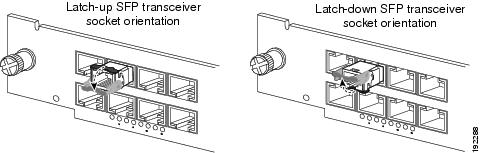
Step 5![]() Leave the bale-clasp in the closed (locked) position and slide the SFP transceiver into the socket until you feel the SFP transceiver snap into place in the socket. An audible click might also be heard as the SFP transceiver latch engages in the socket. (See Figure 1-39.)
Leave the bale-clasp in the closed (locked) position and slide the SFP transceiver into the socket until you feel the SFP transceiver snap into place in the socket. An audible click might also be heard as the SFP transceiver latch engages in the socket. (See Figure 1-39.)
Figure 1-39 Installing the Copper SFP Transceiver
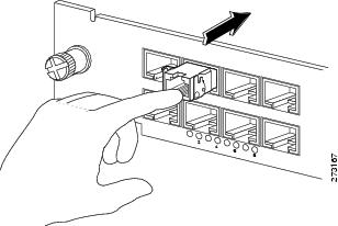
Step 6![]() Connect the network interface cable RJ-45 plug to the SFP RJ-45 connector.
Connect the network interface cable RJ-45 plug to the SFP RJ-45 connector.
Step 7![]() Observe the port status LED:
Observe the port status LED:
- The LED turns green when the SFP transceiver and the target device have an established link.
- The LED turns amber while the port discovers the network topology and searches for loops. This process takes about 30 seconds, and then the LED turns green.
- If the LED is off, the target device might not be turned on, there might be a cable problem, or there might be a problem with the adapter that is installed in the target device. Refer to the Troubleshooting section of your switch hardware guide for solutions to cabling problems.
Installing and Cabling 10GBASE-X XENPAK Transceiver Uplink Ports
To install and cable a XENPAK transceiver uplink port, follow these steps:
Step 1![]() Attach an ESD-preventive wrist strap to your wrist and to the ESD ground connector or to a properly grounded bare metal surface.
Attach an ESD-preventive wrist strap to your wrist and to the ESD ground connector or to a properly grounded bare metal surface.
Step 2![]() Loosen the two screws that secure the uplink port cover plate to the supervisor engine faceplate and remove the cover plate. Save the cover plate for future use.
Loosen the two screws that secure the uplink port cover plate to the supervisor engine faceplate and remove the cover plate. Save the cover plate for future use.
Step 3![]() Remove the XENPAK transceiver from its protective packaging.
Remove the XENPAK transceiver from its protective packaging.
Note![]() Do not remove the optical bore dust plugs until you are directed to do so later in the procedure.
Do not remove the optical bore dust plugs until you are directed to do so later in the procedure.
Step 4![]() Check the label on the XENPAK transceiver body to verify that you have the correct model for your network.
Check the label on the XENPAK transceiver body to verify that you have the correct model for your network.
Step 5![]() Find the transmit (TX) and receive (RX) markings that identify the top side of the XENPAK transceiver.
Find the transmit (TX) and receive (RX) markings that identify the top side of the XENPAK transceiver.
Note![]() On some XENPAK transceivers, the TX and RX marking might be replaced by arrows pointing from the XENPAK transceiver connector (transmit direction or TX) and toward the connector (receive direction or RX).
On some XENPAK transceivers, the TX and RX marking might be replaced by arrows pointing from the XENPAK transceiver connector (transmit direction or TX) and toward the connector (receive direction or RX).
Step 6![]() Position the XENPAK transceiver in front of the uplink port opening and slide the XENPAK transceiver into the opening until you determine that the XENPAK transceiver faceplate is in contact with the supervisor engine faceplate. (See Figure 1-40.) This step ensures that the XENPAK transceiver is fully seated in the supervisor engine socket.
Position the XENPAK transceiver in front of the uplink port opening and slide the XENPAK transceiver into the opening until you determine that the XENPAK transceiver faceplate is in contact with the supervisor engine faceplate. (See Figure 1-40.) This step ensures that the XENPAK transceiver is fully seated in the supervisor engine socket.
Figure 1-40 Installing a XENPAK Transceiver
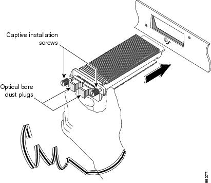
Step 7![]() Tighten the two captive installation screws to secure the XENPAK transceiver in the socket. Avoid cross-threading or overtightening the captive screws.
Tighten the two captive installation screws to secure the XENPAK transceiver in the socket. Avoid cross-threading or overtightening the captive screws.
Note For optical XENPAK transceivers, before removing the dust plugs and making any optical connections, observe the following guidelines:
- Always keep the protective dust plugs on the unplugged fiber-optic cable connectors and the transceiver optical bores until you are ready to make a connection.
- Always inspect and clean the SC connector end-faces just before making any connections. (See the Tip on this page for a pointer to more information about fiber-optic inspection and cleaning.)
- Always grasp the LC connector housing to plug or unplug a fiber-optic cable.
Step 8![]() Remove the dust plugs from the network interface cable SC connectors. Save the dust plugs for future use.
Remove the dust plugs from the network interface cable SC connectors. Save the dust plugs for future use.
Step 9![]() Inspect and clean the SC connector’s fiber-optic end faces. (Refer to “Cleaning the Fiber-Optic Connectors” section.)
Inspect and clean the SC connector’s fiber-optic end faces. (Refer to “Cleaning the Fiber-Optic Connectors” section.)
Step 10![]() Remove the dust plugs from the XENPAK transceiver optical bores.
Remove the dust plugs from the XENPAK transceiver optical bores.
Step 11![]() Immediately attach the network interface cable SC connector to the XENPAK transceiver. (See Figure 1-41.)
Immediately attach the network interface cable SC connector to the XENPAK transceiver. (See Figure 1-41.)
Step 12![]() To connect XENPAK-10GB-CX4 transceivers to a network, perform the following substeps:
To connect XENPAK-10GB-CX4 transceivers to a network, perform the following substeps:
a.![]() Insert the network cable InfiniBand 4x connector into the XENPAK transceiver port. (See Figure 1-42.)
Insert the network cable InfiniBand 4x connector into the XENPAK transceiver port. (See Figure 1-42.)
b.![]() Insert the other end of the network cable into a InfiniBand-compatible target device.
Insert the other end of the network cable into a InfiniBand-compatible target device.
Step 13![]() Observe the port status LED:
Observe the port status LED:
- The LED turns green when the SFP transceiver and the target device have an established link.
- The LED turns amber while STP discovers the network topology and searches for loops. This process takes about 30 seconds, and then the LED turns green.
- If the LED is off, the target device might not be turned on, there might be a cable problem, or there might be a problem with the adapter that is installed in the target device. Refer to the Troubleshooting section of your switch hardware guide for solutions to cabling problems.
Figure 1-41 Cabling an Optical XENPAK Transceiver
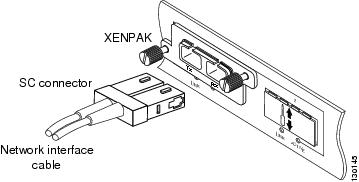
Figure 1-42 Cabling a CX4 (Copper) XENPAK Transceiver
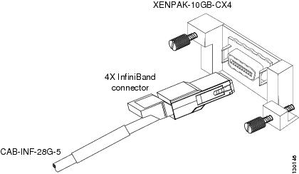
Installing and Cabling 10GBASE-X X2 Transceiver Uplink Ports
The 10-Gigabit X2 transceiver can have either a spring-loaded latch sleeve or a latch sleeve that is not spring loaded. Both transceiver types are functionally identical.
To install an X2 transceiver uplink port, follow these steps:
Step 1![]() Using a small flat-blade screwdriver, carefully pry the X2 transceiver port cover off of the supervisor engine faceplate.
Using a small flat-blade screwdriver, carefully pry the X2 transceiver port cover off of the supervisor engine faceplate.
Use the two arrows on the port cover as guides for inserting the screwdriver blade. Save the port cover for future use.
Step 2![]() Remove the X2 transceiver from its protective packaging.
Remove the X2 transceiver from its protective packaging.
Note![]() Do not remove the optical bore dust plugs until directed to do so later in the procedure.
Do not remove the optical bore dust plugs until directed to do so later in the procedure.
Step 3![]() Check the label on the X2 transceiver body to verify that you have the correct model for your network.
Check the label on the X2 transceiver body to verify that you have the correct model for your network.
Step 4![]() To install the X2 transceiver, do the following:
To install the X2 transceiver, do the following:
a.![]() Insert the X2 transceiver into the transceiver socket on the supervisor engine faceplate. (See Figure 1-43, top view.) Continue sliding the X2 transceiver into the socket until the X2 transceiver EMI gasket is flush against the system module faceplate. The X2 transceiver connector is now mated to the socket connector.
Insert the X2 transceiver into the transceiver socket on the supervisor engine faceplate. (See Figure 1-43, top view.) Continue sliding the X2 transceiver into the socket until the X2 transceiver EMI gasket is flush against the system module faceplate. The X2 transceiver connector is now mated to the socket connector.
b.![]() Verify that the X2 transceiver latches are fully engaged and secure by sliding the transceiver latching sleeve toward the supervisor engine faceplate. (See Figure 1-43, bottom view.)
Verify that the X2 transceiver latches are fully engaged and secure by sliding the transceiver latching sleeve toward the supervisor engine faceplate. (See Figure 1-43, bottom view.)
Figure 1-43 Installing the 10-Gigabit X2 Transceiver
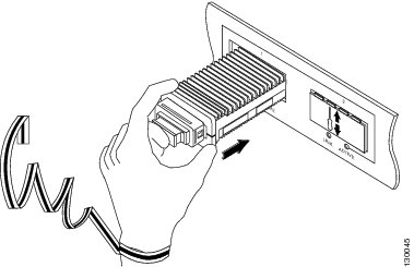
Note![]() 10-Gigabit X2 transceivers are keyed to prevent incorrect insertion.
10-Gigabit X2 transceivers are keyed to prevent incorrect insertion.
Step 5![]() If you are cabling an optical X2 transceiver, perform the following substeps. If you are cabling a CX4 X2 transceiver, go to Step 6.
If you are cabling an optical X2 transceiver, perform the following substeps. If you are cabling a CX4 X2 transceiver, go to Step 6.
Note Before removing the dust plugs and making any optical connections, observe the following guidelines:
- Always keep the protective dust plugs on the unplugged fiber-optic cable connectors and the transceiver optical bores until you are ready to make a connection.
- Always inspect and clean the SC connector end-faces just before making any connections. Refer to the Tip on this page for a pointer to a fiber-optic inspection and cleaning white paper.
- Always grasp the SC connector housing to plug or unplug a fiber-optic cable.
a.![]() Remove the dust plugs from the optical network interface cable SC connectors. Save the dust plugs for future use.
Remove the dust plugs from the optical network interface cable SC connectors. Save the dust plugs for future use.
b.![]() Inspect and clean the SC connector’s fiber-optic end faces. Refer to “Cleaning the Fiber-Optic Connectors” section.
Inspect and clean the SC connector’s fiber-optic end faces. Refer to “Cleaning the Fiber-Optic Connectors” section.
c.![]() Remove the dust plugs from the X2 transceiver optical bores.
Remove the dust plugs from the X2 transceiver optical bores.
d.![]() Immediately attach the network interface cable SC connectors to the X2 transceiver. (See Figure 1-44 for cabling an optical X2 transceiver.)
Immediately attach the network interface cable SC connectors to the X2 transceiver. (See Figure 1-44 for cabling an optical X2 transceiver.)
Figure 1-44 Cabling an Optical 10-Gigabit X2 Transceiver
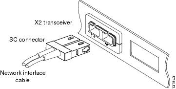
Step 6![]() Plug the InfiniBand cable connector into the CX4 X2 transceiver connector. (See Figure 1-45.) Make sure that the InfiniBand cable connector is aligned with the X2 transceiver.
Plug the InfiniBand cable connector into the CX4 X2 transceiver connector. (See Figure 1-45.) Make sure that the InfiniBand cable connector is aligned with the X2 transceiver.
Figure 1-45 Cabling a CX4 (Copper) 10-Gigabit X2 Transceiver
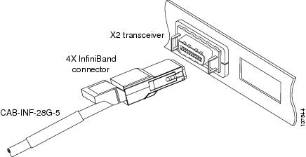
Step 7![]() Carefully route the InfiniBand network cable through the cable management brackets on your system. Figure 1-46 shows how the Infiniband cable should be routed through either a horizontal cable management bracket or a vertical cable management bracket to provide adequate strain relief and support to prevent connector sag or skew.
Carefully route the InfiniBand network cable through the cable management brackets on your system. Figure 1-46 shows how the Infiniband cable should be routed through either a horizontal cable management bracket or a vertical cable management bracket to provide adequate strain relief and support to prevent connector sag or skew.
Note![]() Make sure that you route the InfiniBand cable through cable management brackets to provide adequate strain relief and cable support when cabling CX4 X2 transceivers. The InfiniBand cable is heavy. Without proper support, the InfiniBand cable can cause the cable connector to sag or skew. Misalignment between the cable connector and the transceiver connector can cause intermittent connections between the cable connector pins and the CX4 X2 transceiver pins.
Make sure that you route the InfiniBand cable through cable management brackets to provide adequate strain relief and cable support when cabling CX4 X2 transceivers. The InfiniBand cable is heavy. Without proper support, the InfiniBand cable can cause the cable connector to sag or skew. Misalignment between the cable connector and the transceiver connector can cause intermittent connections between the cable connector pins and the CX4 X2 transceiver pins.
Figure 1-46 InfiniBand Cable Support
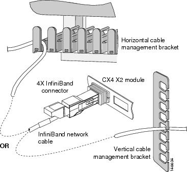
Using the Catalyst 6509-V-E Cable Management System
The optional cable management system on the Catalyst 6509-V-E switch chassis has the capacity to hold several hundred Catagory 5, 6, or 6a copper network interface cables or fiber-optic network interface cables. In order to maximize the capacity of this cable management system, observe the following guidelines:
- In a fully populated chassis with every port in use, you may want to route the network cables coming from the ports on the module in slot 9 (left-most slot in the chassis) out the left side of the chassis and the network cables coming from the ports on the module in slot 1 (right-most slot in the chassis) out of the right side of the chassis and up to the room’s overhead cable trough instead of routing them through the chassis cable management system. Routing the cables this way provides additional room for the cables from the chassis inner slots (slot 2 through slot 8 to be routed through the cable management assembly guides then to the overhead trough).
- You must make sure that there is adequate slack in each network cable so that the cable management assembly can be disengaged and pivoted down to allow access to the fan trays.
- When you route the network cables up from the module port through the cable management guides, you must also allow adequate cable slack to maintain a shallow radius of curvature. Excessive bend in the network cables can break wires and damage connectors. This is especially true with optical-fiber cables, which are more prone to damage from excessive bending and inadequate strain relief than copper cables.
If you are attaching and routing network interface cables on a Catalyst 6509-V-E switch chassis that has the cable management system installed, perform the following steps:
Step 1![]() Remove the cable management system’s front panel assembly by loosening the two captive installation screws. (See Figure 1-47.)
Remove the cable management system’s front panel assembly by loosening the two captive installation screws. (See Figure 1-47.)
Step 2![]() Pivot the front panel assembly up to disengage the front panel tab from the slot at the rear of the cable management assembly. (See Figure 1-48.) This exposes the six cable guides allowing you to route the network interface cables. Set the front panel aside.
Pivot the front panel assembly up to disengage the front panel tab from the slot at the rear of the cable management assembly. (See Figure 1-48.) This exposes the six cable guides allowing you to route the network interface cables. Set the front panel aside.
Figure 1-47 Removing the Cable Management Front Panel Assembly
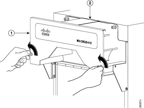
|
|
|
Figure 1-48 Disengaging the Front Panel Tab from the Rear of the Cable Guide Assembly
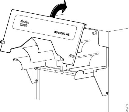
Step 3![]() Connect and route a network cable from one of the chassis module ports up through the cable management guides and up to the room’s overhead cable trough. When routing network interface cables through the cable guides, you must allow adequate slack in the network cable so that the cable’s bend radius is always shallow and so that the cable management assembly can be pivoted down to permit access to the chassis fan tray assembly.
Connect and route a network cable from one of the chassis module ports up through the cable management guides and up to the room’s overhead cable trough. When routing network interface cables through the cable guides, you must allow adequate slack in the network cable so that the cable’s bend radius is always shallow and so that the cable management assembly can be pivoted down to permit access to the chassis fan tray assembly.
Tip![]() To keep the network interface cables organized and minimize the space they occupy, try bundling them in groups of 12 cables (4 bundles of 12 cables per 48-port module). (See Figure 1-49.)
To keep the network interface cables organized and minimize the space they occupy, try bundling them in groups of 12 cables (4 bundles of 12 cables per 48-port module). (See Figure 1-49.)
Figure 1-49 Routing Network Cables Through the Cable Management Assembly
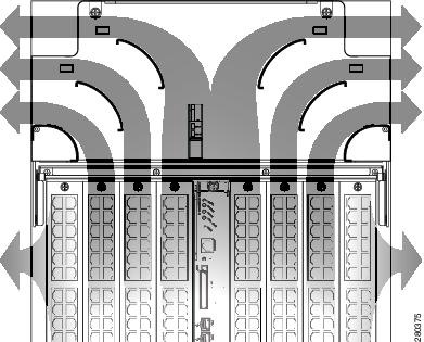
Step 4![]() Repeat step 3 for the remainder of the network interface cables. After routing the remaining network interface cables through the cable management guides, you are ready to reinstall the cable management assembly front panel.
Repeat step 3 for the remainder of the network interface cables. After routing the remaining network interface cables through the cable management guides, you are ready to reinstall the cable management assembly front panel.
Step 5![]() Position the front panel assembly and insert the front panel tab into the slot at the back of the cable guide system. (See Figure 1-50.)
Position the front panel assembly and insert the front panel tab into the slot at the back of the cable guide system. (See Figure 1-50.)
Step 6![]() Pivot the front panel assembly down. Make sure that all of the network cables are properly routed, clear of the front panel and that none of them are being pinched. Align the front panel so that you can start the two captive installation screws on the front panel.
Pivot the front panel assembly down. Make sure that all of the network cables are properly routed, clear of the front panel and that none of them are being pinched. Align the front panel so that you can start the two captive installation screws on the front panel.
Step 7![]() Verify that the tab is still engaged in the slot on the back of the cable guide assembly and tighten the two captive installation screws on the front panel assembly. (See Figure 1-51.)
Verify that the tab is still engaged in the slot on the back of the cable guide assembly and tighten the two captive installation screws on the front panel assembly. (See Figure 1-51.)
Figure 1-50 Reinstalling the Cable Guide Front Panel Assembly
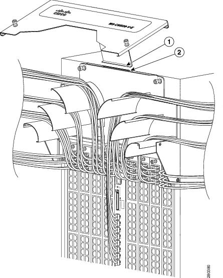
|
|
|
Figure 1-51 Securing the Cable Guide Front Panel Assembly
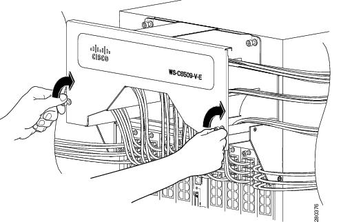
Verifying Switch Chassis Installation
To verify the switch chassis installation, follow these steps:
Step 1![]() Verify that the ejector levers of each module are fully closed (parallel to the faceplate) to ensure that the supervisor engine and all switching modules are fully seated in the backplane connectors.
Verify that the ejector levers of each module are fully closed (parallel to the faceplate) to ensure that the supervisor engine and all switching modules are fully seated in the backplane connectors.
Step 2![]() Check the captive installation screws of each module, the power supply, and the fan assembly. Tighten any loose captive installation screws.
Check the captive installation screws of each module, the power supply, and the fan assembly. Tighten any loose captive installation screws.
Step 3![]() Verify that all empty module slots have blank faceplates installed and that the screws holding the plates in place are tight. The blank faceplates optimize the air flow through the chassis and contain electromagnetic interference.
Verify that all empty module slots have blank faceplates installed and that the screws holding the plates in place are tight. The blank faceplates optimize the air flow through the chassis and contain electromagnetic interference.
Warning![]() Blank faceplates and cover panels serve three important functions: they prevent exposure to hazardous voltages and currents inside the chassis; they contain electromagnetic interference (EMI) that might disrupt other equipment; and they direct the flow of cooling air through the chassis. Do not operate the system unless all cards, faceplates, front covers, and rear covers are in place.
Blank faceplates and cover panels serve three important functions: they prevent exposure to hazardous voltages and currents inside the chassis; they contain electromagnetic interference (EMI) that might disrupt other equipment; and they direct the flow of cooling air through the chassis. Do not operate the system unless all cards, faceplates, front covers, and rear covers are in place.
Statement 1029
Step 4![]() Turn on the power supply switches to power up the system. During the power-up sequence, the system performs a series of bootup diagnostic tests.
Turn on the power supply switches to power up the system. During the power-up sequence, the system performs a series of bootup diagnostic tests.
Additional system diagnostic tests are available. These tests allow you to perform a complete sanity check on the system prior to inserting the system into your network and to monitor the health of the system while the system is running. Refer to the “Online Diagnostics” section for further information.
Tip When prestaging systems in a nonproduction environment, we recommend that you run all diagnostic tests, including the disruptive tests, to prescreen the systems for any failures.
Online Diagnostics
The Catalyst 6500 series systems running Cisco IOS have many levels of online diagnostic capabilities. The online diagnostics are divided into four categories:
- Bootup—Bootup diagnostics automatically run during bootup, module OIR, or switchover to a backup supervisor engine.
- Background health—Monitoring diagnostic tests are continuously run by the system to monitor system health.
- On-demand online diagnostics—On-demand online diagnostics can be used to run any test from the CLI. You can also run on-demand online diagnostics to perform a sanity check on the system hardware. Some of these tests are disruptive and will impact traffic flow.You must follow the on-demand diagnostic guidelines exactly to avoid false failures.
- Scheduled diagnostics—Scheduled diagnostics can be used to run any of the above tests at user-designated intervals.
For complete information on the online diagnostic tests and how to run them, refer to Chapter 51 in the Catalyst 6500 Series Switch Cisco IOS Software Configuration Guide, Release 12.2SX.
 Feedback