Removing and Replacing FRUs
 |
Warning |
|
Warning |
|
Warning |
This chapter tells you how to remove and replace Catalyst 4500 series field-replaceable units (FRUs). The information is presented in these sections:
•![]() Removing and Replacing the Power Supply
Removing and Replacing the Power Supply
•![]() Removing and Replacing the Chassis Fan Assembly
Removing and Replacing the Chassis Fan Assembly
•![]() Replacing Backplane Modules on a Catalyst 4507R or 4510R Switch
Replacing Backplane Modules on a Catalyst 4507R or 4510R Switch
For instructions on installing and replacing supervisor engine and switching modules, refer to the Catalyst 4500 Series Module Installation Guide.
Removing and Replacing the Power Supply
This section describes how to remove and install the AC-input power supply and DC-input power supply for the Catalyst 4500 series switches. This information is presented in the following sections:
•![]() Removing an AC-Input Power Supply
Removing an AC-Input Power Supply
•![]() Installing an AC-Input Power Supply
Installing an AC-Input Power Supply
•![]() Removing a DC-Input Power Supply
Removing a DC-Input Power Supply
•![]() Installing a DC-Input Power Supply
Installing a DC-Input Power Supply
|
Warning |
Figure 4-1 and Figure 4-2 show the AC-input power supplies. Figure 4-3 and Figure 4-4 show a the DC-input power supplies. Locate your power supply and notice the location of the captive installation screws.

Note ![]() The power supplies are hot-swappable, so in redundant mode you will not need to power down the switch to replace or upgrade most power supplies. In combined mode some slots may lose power during an upgrade or power supply replacement.
The power supplies are hot-swappable, so in redundant mode you will not need to power down the switch to replace or upgrade most power supplies. In combined mode some slots may lose power during an upgrade or power supply replacement.
Figure 4-1 AC-Input Power Supply
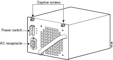
Figure 4-2 4200 W Dual-Input AC Power Supply
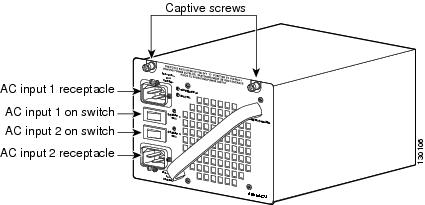
Figure 4-3 DC-Input Power Supply
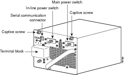
Figure 4-4 1400 W DC Triple-input Power Supply
Required Tools
You will need a flathead or Phillips screwdriver to perform these procedures.
Removing an AC-Input Power Supply
Follow these steps to remove the AC-input power supply:
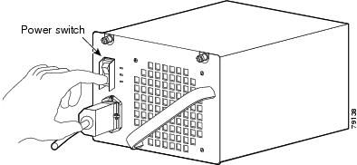
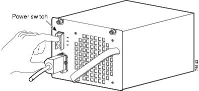
Step 1 ![]() Press the power switch on the AC-input power supply down to the off (O) position (see Figure 4-5).
Press the power switch on the AC-input power supply down to the off (O) position (see Figure 4-5).
Figure 4-5 Powering Off the Power Switch
Note ![]() There are two on/off switches on a 4200 W AC power supply, one for each input.
There are two on/off switches on a 4200 W AC power supply, one for each input.
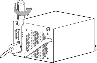
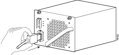
Step 2 ![]() Loosen the side-clamp screw on the right side of the power cord plug (see Figure 4-6).
Loosen the side-clamp screw on the right side of the power cord plug (see Figure 4-6).
Figure 4-6 Loosening the Side-Clamp Screw
Step 3 ![]() Disconnect the power cord from the power supply being removed.
Disconnect the power cord from the power supply being removed.
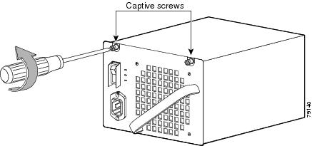
Step 4 ![]() Loosen the two captive screws (see Figure 4-7).
Loosen the two captive screws (see Figure 4-7).
Figure 4-7 Loosening the Captive Screws

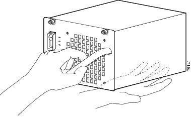
Step 5 ![]() Grasp the power supply handle with one hand. Place your other hand underneath to support the bottom of the power supply, as shown in Figure 4-8.
Grasp the power supply handle with one hand. Place your other hand underneath to support the bottom of the power supply, as shown in Figure 4-8.
Figure 4-8 Handling an AC-Input Power Supply
Step 6 ![]() Pull the power supply out of the bay and set it aside.
Pull the power supply out of the bay and set it aside.
Step 7 ![]() If the power supply bay is to remain empty, install a blank power supply filler plate over the opening. Secure the filler plate with the two mounting screws and tighten them with a screwdriver.
If the power supply bay is to remain empty, install a blank power supply filler plate over the opening. Secure the filler plate with the two mounting screws and tighten them with a screwdriver.
Installing an AC-Input Power Supply
|
Warning |
Follow these steps to install an AC-input power supply:
Step 1 ![]() Make sure that the power supply you are installing is not plugged in to a power outlet and that the power cord is not connected to the power supply.
Make sure that the power supply you are installing is not plugged in to a power outlet and that the power cord is not connected to the power supply.
Step 2 ![]() Remove the two Phillips-head screws from the power supply filler plate (if a filler plate is present).
Remove the two Phillips-head screws from the power supply filler plate (if a filler plate is present).
Step 3 ![]() Remove the power supply filler plate (if one is present) and set it aside.
Remove the power supply filler plate (if one is present) and set it aside.
Step 4 ![]() Grasp the power supply handle with one hand. Place your other hand underneath to support the bottom of the power supply, as shown earlier in Figure 4-8.
Grasp the power supply handle with one hand. Place your other hand underneath to support the bottom of the power supply, as shown earlier in Figure 4-8.
Step 5 ![]() Slide the power supply all the way into the power supply bay.
Slide the power supply all the way into the power supply bay.
Step 6 ![]() Using a screwdriver, tighten the two captive installation screws (see Figure 4-1) on the front panel of the AC-input power supply.
Using a screwdriver, tighten the two captive installation screws (see Figure 4-1) on the front panel of the AC-input power supply.
Step 7 ![]() Make sure the power supply power switch is in the off position (O).
Make sure the power supply power switch is in the off position (O).
Step 8 ![]() Before you connect the power supply to a power source, ensure that all site power and grounding requirements described in the Site Preparation and Safety Guide have been met.
Before you connect the power supply to a power source, ensure that all site power and grounding requirements described in the Site Preparation and Safety Guide have been met.
Step 9 ![]() Plug the power cord into the power supply (see Figure 4-9).
Plug the power cord into the power supply (see Figure 4-9).
Figure 4-9 Plugging the Power Cord into the Power Supply
Step 10 ![]() Connect the other end of the power cord to an AC-power input source.
Connect the other end of the power cord to an AC-power input source.
Step 11 ![]() Press the power switch down to the on (|) position (see Figure 4-10).
Press the power switch down to the on (|) position (see Figure 4-10).
Figure 4-10 Powering On the Power Supply
Step 12 ![]() Verify power supply operation by checking the power supply's front-panel LEDs. You should see the following:
Verify power supply operation by checking the power supply's front-panel LEDs. You should see the following:
•![]() The LED labeled GOOD is green.
The LED labeled GOOD is green.
•![]() The LED labeled FAIL is not lit.
The LED labeled FAIL is not lit.
•![]() The LED labeled FAN OK is green.
The LED labeled FAN OK is green.
Step 13 ![]() Check the power supply and system status from the system console by entering the show system command (Catalyst Operating System) or the show power command (Cisco IOS). For more information on this command, refer to the command reference publication for your switch.
Check the power supply and system status from the system console by entering the show system command (Catalyst Operating System) or the show power command (Cisco IOS). For more information on this command, refer to the command reference publication for your switch.
Step 14 ![]() If the LEDs or the show system command (Catalyst Operating System) or the show power command (Cisco IOS) output indicate a power problem or other system problem, see Chapter 5 "Troubleshooting," for more information.
If the LEDs or the show system command (Catalyst Operating System) or the show power command (Cisco IOS) output indicate a power problem or other system problem, see Chapter 5 "Troubleshooting," for more information.
Removing a DC-Input Power Supply
This section describes how to remove a DC-input power supply.
Required Tools
You will need the following tools to perform this procedure:
•![]() A Phillips screwdriver
A Phillips screwdriver
•![]() A 10-mm wrench/socket
A 10-mm wrench/socket
Removal Procedure
|
Warning |
Follow these steps to remove a DC-input power supply:
Step 1 ![]() Turn off the in-line power switch. (Single input only. The triple-input power supply does not have this switch.)
Turn off the in-line power switch. (Single input only. The triple-input power supply does not have this switch.)
Step 2 ![]() Turn off the main power switch.
Turn off the main power switch.
Step 3 ![]() Verify that power is off to the DC circuit on the power supply you are removing.
Verify that power is off to the DC circuit on the power supply you are removing.
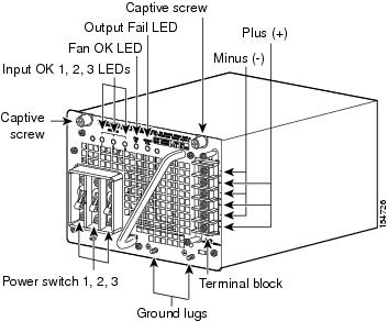
Step 4 ![]() Loosen the screw on the terminal block cover and remove it from the terminal block (see Figure 4-11 or Figure 4-12). The triple-input power supply has two screws on the cover.
Loosen the screw on the terminal block cover and remove it from the terminal block (see Figure 4-11 or Figure 4-12). The triple-input power supply has two screws on the cover.
Figure 4-11 DC-Input Power Supply
Figure 4-12 DC Triple-input Power Supply
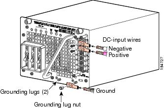
Step 5 ![]() Disconnect the DC-input wires from the terminal block. Disconnect the ground wire last (see Figure 4-13 or Figure 4-14).
Disconnect the DC-input wires from the terminal block. Disconnect the ground wire last (see Figure 4-13 or Figure 4-14).
|
Warning |
Figure 4-13 Connecting the DC-Input Wires
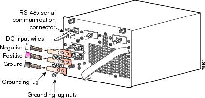
Figure 4-14 Connecting the DC-Input Wires (Triple-input Power Supply)
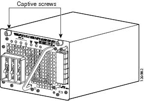
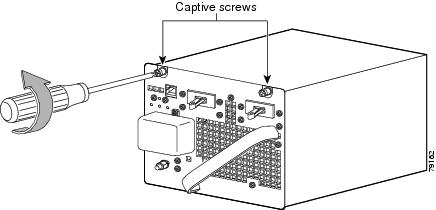
Step 6 ![]() Using a screwdriver, loosen and remove the captive screws on the power supply. (See Figure 4-15, which shows the single input power supply. The triple-input power supply has captive screws in the same location.)
Using a screwdriver, loosen and remove the captive screws on the power supply. (See Figure 4-15, which shows the single input power supply. The triple-input power supply has captive screws in the same location.)
Figure 4-15 Loosening the Captive Screws
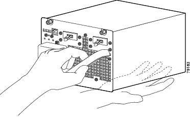
Step 7 ![]() Grasp the power supply handle with one hand. Place your other hand underneath as you slowly pull the power supply out of the bay (see Figure 4-16).
Grasp the power supply handle with one hand. Place your other hand underneath as you slowly pull the power supply out of the bay (see Figure 4-16).
Figure 4-16 Handling a DC-Input Power Supply
Step 8 ![]() If the bay is to remain empty, install a blank power supply filler plate over the opening and secure it with the mounting screws. This protects the inner chassis from dust and prevents accidental contact with live voltage at the rear of the bay.
If the bay is to remain empty, install a blank power supply filler plate over the opening and secure it with the mounting screws. This protects the inner chassis from dust and prevents accidental contact with live voltage at the rear of the bay.
Installing a DC-Input Power Supply
This section describes how to install a DC-input power supply.
Required Tools
You will need the following tools to perform this procedure:
•![]() A Phillips screwdriver
A Phillips screwdriver
•![]() A 10-mm wrench/socket
A 10-mm wrench/socket
•![]() Connectors and wire for the DC circuit or circuits
Connectors and wire for the DC circuit or circuits
Installation Procedure
|
Warning |
|
Warning |
|
Warning |
Follow these steps to install a DC-input power supply, connect it to a power source, and verify its operation:
Step 1 ![]() Verify that power is off to the DC circuit or circuits on the power supply you are installing.
Verify that power is off to the DC circuit or circuits on the power supply you are installing.
Step 2 ![]() Grasp the power supply handle with one hand. Place your other hand underneath it as you slowly insert the power supply into the bay (as shown earlier in Figure 4-16).
Grasp the power supply handle with one hand. Place your other hand underneath it as you slowly insert the power supply into the bay (as shown earlier in Figure 4-16).
Step 3 ![]() Using a screwdriver, tighten the captive screws on the power supply (see Figure 4-15).
Using a screwdriver, tighten the captive screws on the power supply (see Figure 4-15).
Step 4 ![]() Before you connect the power supply to a power source, ensure that all site power and grounding requirements have been met.
Before you connect the power supply to a power source, ensure that all site power and grounding requirements have been met.
Step 5 ![]() Connect the DC-input wires to the power supply terminal block. The proper wiring sequence is ground to ground, positive to positive, and negative to negative (see Figure 4-13 or Figure 4-14 depending on your installation).
Connect the DC-input wires to the power supply terminal block. The proper wiring sequence is ground to ground, positive to positive, and negative to negative (see Figure 4-13 or Figure 4-14 depending on your installation).
The 1400W triple-input power supply has two grounding posts; use the one that is most convenient for your installation.
|
Warning |
Step 6 ![]() Replace the terminal cover.
Replace the terminal cover.
Step 7 ![]() Connect the other end of the power cords to a DC-power input source.
Connect the other end of the power cords to a DC-power input source.
Step 8 ![]() Verify power supply operation by checking the power supply's front-panel LEDs. You should see the following:
Verify power supply operation by checking the power supply's front-panel LEDs. You should see the following:
•![]() The LED labeled INPUT OK is green.
The LED labeled INPUT OK is green.
•![]() The LED labeled OUTPUT FAIL is not lit.
The LED labeled OUTPUT FAIL is not lit.
Step 9 ![]() Check the power supply and system status from the system console by entering the show system command (Catalyst Operating System) or the show power command (Cisco IOS). For more information on these commands, refer to the command reference publication for your switch and software.
Check the power supply and system status from the system console by entering the show system command (Catalyst Operating System) or the show power command (Cisco IOS). For more information on these commands, refer to the command reference publication for your switch and software.
Step 10 ![]() If the LEDs or the show system command (Catalyst Operating System) or the show power command (Cisco IOS) output indicate a power problem or other system problem, see Chapter 5 "Troubleshooting," for more information.
If the LEDs or the show system command (Catalyst Operating System) or the show power command (Cisco IOS) output indicate a power problem or other system problem, see Chapter 5 "Troubleshooting," for more information.
Removing and Replacing the Chassis Fan Assembly
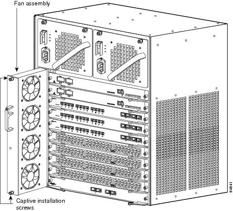
This section describes how to remove and install the chassis fan assembly for the Catalyst 4500 series switches. See Figure 4-17 for the Catalyst 4503 system fan assembly, Figure 4-18 for the Catalyst 4506 system fan assembly, Figure 4-19 for the Catalyst 4507R system fan assemblies, and Figure 4-20 for the Catalyst 4510R system fan assemblies.
Figure 4-17 Catalyst 4503 System Fan Assembly
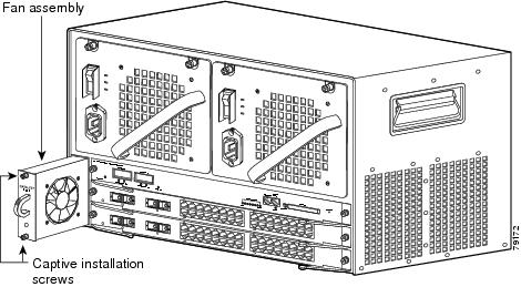
Figure 4-18 Catalyst 4506 System Fan Assembly
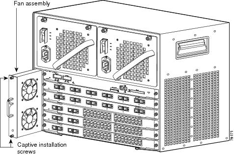
Figure 4-19 Catalyst 4507R System Fan Assembly
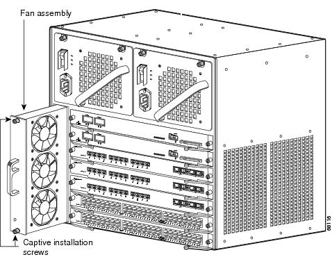
Figure 4-20 Catalyst 4510R System Fan Assembly
Required Tools
You will need a Phillips screwdriver for the following two procedures.
Removing the Fan Assembly
|
Warning |
Follow these steps to remove the existing chassis fan assembly:
Step 1 ![]() Loosen the two captive installation screws on the fan assembly by turning them counterclockwise.
Loosen the two captive installation screws on the fan assembly by turning them counterclockwise.
Step 2 ![]() Grasp the fan assembly with both hands and pull it outward; gently move it side to side if necessary to unseat it from the backplane. Slide it out of the chassis and place it in a safe place.
Grasp the fan assembly with both hands and pull it outward; gently move it side to side if necessary to unseat it from the backplane. Slide it out of the chassis and place it in a safe place.
Installing the Fan Assembly
Follow these steps to install the new fan assembly:
Step 1 ![]() Hold the fan assembly with the fans facing to the right.
Hold the fan assembly with the fans facing to the right.
Step 2 ![]() Place the fan assembly into the fan assembly bay so it rests on the chassis, and then lift the fan assembly up slightly, aligning the top and bottom guides.
Place the fan assembly into the fan assembly bay so it rests on the chassis, and then lift the fan assembly up slightly, aligning the top and bottom guides.
Step 3 ![]() Slide the fan assembly into the chassis until the two captive installation screws make contact with the chassis.
Slide the fan assembly into the chassis until the two captive installation screws make contact with the chassis.
Step 4 ![]() Using a screwdriver, tighten the two captive installation screws by turning them clockwise.
Using a screwdriver, tighten the two captive installation screws by turning them clockwise.
Verifying the Installation
Note ![]() To check the operation of the fans, you need to power up the chassis.
To check the operation of the fans, you need to power up the chassis.
Follow these steps to verify that the new fan assembly was installed correctly:
Step 1 ![]() Listen for the fans; you should immediately hear them operating. If you do not hear them, ensure that the fan assembly is inserted completely in the chassis and that the faceplate is flush with the switch back panel.
Listen for the fans; you should immediately hear them operating. If you do not hear them, ensure that the fan assembly is inserted completely in the chassis and that the faceplate is flush with the switch back panel.
Step 2 ![]() The fan tray LED should light and be green.
The fan tray LED should light and be green.
Step 3 ![]() If after several attempts the fans do not operate, or if you experience trouble with the installation (for instance, if the captive installation screws do not align with the chassis holes), contact the Cisco TAC for assistance.
If after several attempts the fans do not operate, or if you experience trouble with the installation (for instance, if the captive installation screws do not align with the chassis holes), contact the Cisco TAC for assistance.
Replacing Backplane Modules on a Catalyst 4507R or 4510R Switch
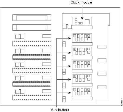
There are 5 redundancy modules (also called mux buffers) and 1 clock module on a Catalyst 4507R chassis backplane. A Catalyst 4510 has 8 redundancy modules on its backplane. They are accessible from the front if the switching modules and supervisor engines are removed. There are two types of redundancy modules, and they are interchangeable.
The clock module replacement procedure is identical to the redundancy module replacement procedure, the connectors are the same. These modules are not hot-swappable, the switch must be taken out of service to replace them.
To replace the backplane modules:
Step 1 ![]() Make sure you are grounded with an ESD strap.
Make sure you are grounded with an ESD strap.
Step 2 ![]() Turn off the power to the chassis.
Turn off the power to the chassis.
Step 3 ![]() Remove all supervisor engines and switching modules from the chassis, and find the backplane modules you need to replace.
Remove all supervisor engines and switching modules from the chassis, and find the backplane modules you need to replace.
Note ![]() Keep a record of switching moduleand their slots, so that you can put them back correctly.
Keep a record of switching moduleand their slots, so that you can put them back correctly.
Note ![]() Generic switching module replacement procedures are documented at:
Generic switching module replacement procedures are documented at:
http://www.cisco.com/univercd/cc/td/doc/product/lan/cat4000/hw_doc/gmdcf_nt.htm#wp21932
Figure 4-21 shows the front view of the backplane with supervisors and switching modules removed.
Figure 4-21 Catalyst 4507R Backplane
Step 4 ![]() If you are removing a clock module, remove the two screws that attach the module to the backplane.
If you are removing a clock module, remove the two screws that attach the module to the backplane.
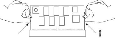
Step 5 ![]() Find the seating levers on both sides of the connector for the module you wish to replace. (See Figure 4-22.)
Find the seating levers on both sides of the connector for the module you wish to replace. (See Figure 4-22.)
Figure 4-22 Finding the Seating Levers
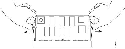
Step 6 ![]() To release the module from its connector, pull the levers outward with your fingernails. The module will pop out slightly. (See Figure 4-23.)
To release the module from its connector, pull the levers outward with your fingernails. The module will pop out slightly. (See Figure 4-23.)
Figure 4-23 Releasing the Module
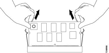
Step 7 ![]() Pull out the module while holding the top left and top right corners. (See Figure 4-24.)
Pull out the module while holding the top left and top right corners. (See Figure 4-24.)
Note ![]() When handling the modules, do not touch the chips or the gold edge contacts on the module.
When handling the modules, do not touch the chips or the gold edge contacts on the module.
Figure 4-24 Removing the Module
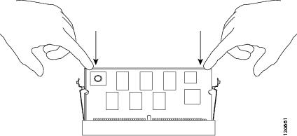
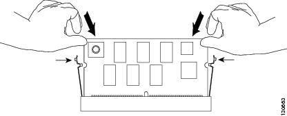
Step 8 ![]() Put the replacement module in at roughly a 30 degree angle, and gently push the module down. Make sure you apply force evenly on the left and right. (See Figure 4-25.)
Put the replacement module in at roughly a 30 degree angle, and gently push the module down. Make sure you apply force evenly on the left and right. (See Figure 4-25.)
Figure 4-25 Seating the Replacement Module
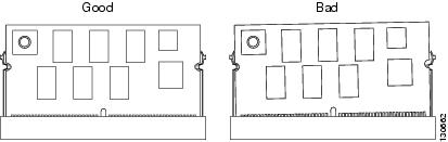
Step 9 ![]() Make sure the module is fully seated. (See Figure 4-26.)
Make sure the module is fully seated. (See Figure 4-26.)
Figure 4-26 Correct Module Seating
Step 10 ![]() Push the module toward the back of the chassis and make sure it is clipped in by the levers on both sides. (See Figure 4-27.)
Push the module toward the back of the chassis and make sure it is clipped in by the levers on both sides. (See Figure 4-27.)
Figure 4-27 Securing the Module
Step 11 ![]() Repeat Step 4 to Step 10 for the other modules you need to replace.
Repeat Step 4 to Step 10 for the other modules you need to replace.
Step 12 ![]() If you are installing a clock module, secure the module to the backplane using the screws from the earlier removal.
If you are installing a clock module, secure the module to the backplane using the screws from the earlier removal.
Step 13 ![]() Replace the supervisor engines and switching modules to their previous slots.
Replace the supervisor engines and switching modules to their previous slots.
Step 14 ![]() Restore power to the switch.
Restore power to the switch.
Verify the New Modules
After the switch is reassembled and power is restored, connect a terminal to the supervisor engine and monitor the boot process. Look for the following messages (or any others), which may indicate a problem with the replaced modules:
00:00:20: %C4K_SUPERVISOR-2-MUXBUFFERNOTPRESENT: Mux buffer
(WS-X4K-MUX) 3 is not present
00:00:20: %C4K_SUPERVISOR-2-MUXBUFFERNOTPRESENT: Mux buffer
(WS-X4K-MUX) 4 is not present
00:00:20: %C4K_SUPERVISOR-2-MUXBUFFERNOTPRESENT: Mux buffer
(WS-X4K-MUX) 7 is not present
The above messages (either at startup or output from a show logging command) indicate that the mux-buffer is not present in slots 3, 4 and 7. You need to reinsert and reseat the modules in those slots.
If the switch has already started up, you may also verify the correct function of the new modules with the show logging command.
 Feedback