Product Overview
This chapter provides an overview of the features and components of the Catalyst 4500 series switches. The Catalyst 4500 series switches are the Catalyst 4503 switch, the Catalyst 4506 switch, the Catalyst 4507R switch, and the Catalyst 4510R switch. The information is presented in these major sections:
Switch Features
The following sections describe the features of the Catalyst 4500 series switches:
•![]() Catalyst 4503 Switch Features
Catalyst 4503 Switch Features
•![]() Catalyst 4506 Switch Features
Catalyst 4506 Switch Features
•![]() Catalyst 4507R Switch Features
Catalyst 4507R Switch Features
•![]() Catalyst 4510R Switch Features
Catalyst 4510R Switch Features
Catalyst 4503 Switch Features
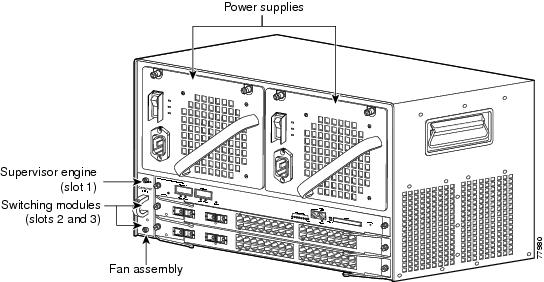
The Catalyst 4503 switch (see Figure 1-1) is a three-slot switch designed for high-performance, high-density wiring closet applications.
Figure 1-1 Catalyst 4503 Switch (Front View)
The Catalyst 4503 switch supports the Supervisor Engine II, II+, II+TS, II+10GE, IV, V, V-10GE and 6-E. The supervisor engine has a nonblocking, full-duplex, switching fabric that provides connections between the supervisor engine and the switching modules. The Gigabit Ethernet ports can be configured with any combination of copper 1000BASE-T, shortwave SX, LX/LH, and ZX interfaces, or CWDM and DWDM GBICs. For a description of GBICs, refer to the Catalyst 4500 Series Module Installation Guide or the Catalyst 4500 Series Supervisor Engines and Switching Modules Installation Note. Some supervisor engines use SFP modules for Gigabit Ethernet connections, or X2 modules for 10-Gigabit Ethernet connections. Refer to the installation note for your supervisor engine for more details on these modules.
Slot 1 is reserved for the supervisor engine only, which provides switching, local and remote management, and switch-status monitoring. Slots 2 and 3 are available for switching modules.
Table 1-1 describes the features of the Catalyst 4503 switch.
|
|
|
|---|---|
Ethernet speeds |
• • Note • • |
Standard equipment |
• • • |
Power supplies |
• • |
Supervisor engine support |
• • • Note |
Switching module support |
• • • • • • • • • • • • • • • – |
Switching module support (continued) |
• • • • • • • • • • • • • • |
1 You will need to configure the 1400 W DC input current as appropriate for the model of switch. Refer to "Specifications." |
Catalyst 4506 Switch Features
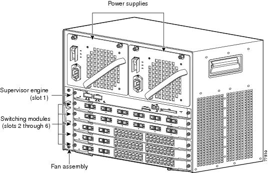
The Catalyst 4506 switch (see Figure 1-2) is a six-slot switch designed for high-performance, high-density wiring closet applications.
Figure 1-2 Catalyst 4506 Switch (Front View)
The Catalyst 4506 switch supports the Supervisor Engine II, II+, II+10GE, III, IV, V, V-10GE, and 6-E. The supervisor engine has a nonblocking, full-duplex, switching fabric that provides connections between the supervisor engine and the switching modules. The Gigabit Ethernet ports can be configured with any combination of copper 1000BASE-T, shortwave SX, LX/LH, and ZX interfaces, or CWDM and DWDM GBICs. For a description of GBICs, refer to the Catalyst 4500 Series Module Installation Guide or the Catalyst 4500 Series Supervisor Engines and Switching Modules Installation Note. Some supervisor engines use SFP modules for Gigabit Ethernet connections, or X2 modules for 10-Gigabit Ethernet connections. Refer to the installation note for your supervisor engine for more details on these modules.
Slot 1 is reserved for the supervisor engine only, which provides switching, local and remote management, and switch-status monitoring. Slots 2 through 6 are available for switching modules.
Table 1-2 describes the features of the Catalyst 4506 switch.
|
|
|
|---|---|
Ethernet speeds |
• • Note • • |
Standard equipment |
• • • |
Power supplies |
• • |
Supervisor engine support |
• • • Note |
Switching module support |
• • • • • • • • • • • • |
Switching module support (continued) |
• • • • • • • • • • • • • • • • • |
1 You will need to configure the 1400 W DC input current as appropriate for the model of switch. Refer to "Specifications." |
Catalyst 4507R Switch Features
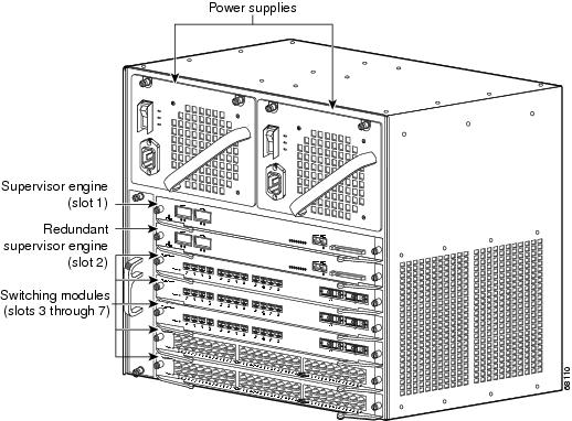
The Catalyst 4507R switch (see Figure 1-3) is a seven-slot switch designed for high-performance, high-density wiring closet applications.
Figure 1-3 Catalyst 4507R Switch (Front View)
The Catalyst 4507R switch supports the Supervisor Engine II+,II+10GE, IV, V, V-10GE, and 6-E. The supervisor engine has two Gigabit Ethernet ports and a nonblocking, full-duplex, switching fabric that provides connections between the supervisor engine and the switching modules. The Gigabit Ethernet ports can be configured with any combination of copper 1000BASE-T, shortwave SX, LX/LH, and ZX interfaces, or CWDM and DWDM GBICs. For a description of GBICs, refer to the Catalyst 4000 Series Module Installation Guide or the Catalyst 4500 Series Supervisor Engines and Switching Modules Installation Note. Some supervisor engines use SFP modules for Gigabit Ethernet connections, or X2 modules for 10-Gigabit Ethernet connections. Refer to the installation note for your supervisor engine for more details on these modules.
Slot 1 is reserved for the supervisor engine only, which provides switching, local and remote management, and switch-status monitoring. Slot 2 is reserved for a redundant supervisor engine only. Slots 3 through 7 are available for switching modules.
Table 1-3 describes the features of the Catalyst 4507R switch.
|
|
|
|---|---|
Ethernet speeds |
• • Note • • |
Standard equipment |
• • • |
Power supplies |
• • |
Supervisor engine support |
• Note • • Note |
Switching module support |
• • • – • • • • • • • • • • |
Switching module support (continued) |
• • • • • • • • • • • • • • • |
1 You will need to configure the 1400 W DC input current as appropriate for the model of switch. Refer to "Specifications." |
Catalyst 4510R Switch Features
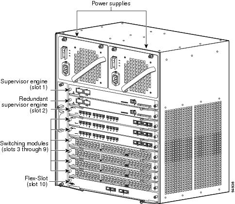
The Catalyst 4510R switch (see Figure 1-4) is a ten-slot switch designed for high-performance, high-density wiring closet applications.
Figure 1-4 Catalyst 4510R Switch (Front View)
The Catalyst 4510R switch supports the Supervisor Engine V, V-10GE, and 6-E. The supervisor engine has a nonblocking, full-duplex, switching fabric that provides connections between the supervisor engine and the switching modules. The Gigabit Ethernet ports can be configured with any combination of copper 1000BASE-T, shortwave SX, LX/LH, and ZX interfaces, or CWDM and DWDM GBICs. For a description of GBICs, refer to the Catalyst 4500 Series Module Installation Guide or the Catalyst 4500 Series Supervisor Engines and Switching Modules Installation Note. Some supervisor engines use SFP modules for Gigabit Ethernet connections, or X2 modules for 10 Gigabit Ethernet connections. Refer to the installation note for your supervisor engine for more details on these modules.
Slot 1 is reserved for the supervisor engine only, which provides switching, local and remote management, and switch-status monitoring. Slot 2 is reserved for a redundant supervisor engine only. Slots 3 through 9 are available for switching modules. When using a Supervisor Engine V, slot 10 is a flex-slot for use with the 2-port Gigabit Ethernet switching module (WS-X4302-GB) or the Access Gateway Module (WS-X4604-GWY) only. When using a Supervisor Engine V-10GE, any supported module may be used in slot 10.
Table 1-4 describes the features of the Catalyst 4510R switch.
|
|
|
|---|---|
Ethernet speeds |
• • Note • • |
Standard equipment |
• • • |
Power supplies |
• • |
Supervisor engine support |
• Note • • Note |
Switching module support |
• • • • • • • • • • • • • |
Switching module support (continued) |
• • – • • • • • • • • • • • • • |
1 You will need to configure the 1400 W DC input current as appropriate for the model of switch. Refer to "Specifications." 2 1000W AC and 1300W AC power supplies will fit and function; however, power management is cautioned and only some configurations will have adequate power. Please refer to the Cisco Power Calculator at http://tools.cisco.com/cpc/ before configuring these power supplies. |
Supervisor Engines
The following supervisor engines are available for the Catalyst 4500 series switches:
•![]() Supervisor Engine II (WS-X4013) (Figure 1-5)
Supervisor Engine II (WS-X4013) (Figure 1-5)
•![]() Supervisor Engine II-Plus (WS-X4013+) (Figure 1-6)
Supervisor Engine II-Plus (WS-X4013+) (Figure 1-6)
•![]() Supervisor Engine II-Plus TS (WS-X4013+TS) (Figure 1-7)
Supervisor Engine II-Plus TS (WS-X4013+TS) (Figure 1-7)
•![]() Supervisor Engine II-Plus 10GE (WS-X4013+10GE) (Figure 1-8)
Supervisor Engine II-Plus 10GE (WS-X4013+10GE) (Figure 1-8)
•![]() Supervisor Engine III (WS-X4014) (Figure 1-9)
Supervisor Engine III (WS-X4014) (Figure 1-9)
•![]() Supervisor Engine IV (WS-X4515) (Figure 1-10)
Supervisor Engine IV (WS-X4515) (Figure 1-10)
•![]() Supervisor Engine V (WS-X4516) (Figure 1-11)
Supervisor Engine V (WS-X4516) (Figure 1-11)
•![]() Supervisor Engine V-10GE (WS-X4516-10GE) (Figure 1-12)
Supervisor Engine V-10GE (WS-X4516-10GE) (Figure 1-12)

Note ![]() E-series supervisor engines may in some cases also work on Catalyst 4500 series systems, refer to the installation note for your supervisor engine for details.
E-series supervisor engines may in some cases also work on Catalyst 4500 series systems, refer to the installation note for your supervisor engine for details.
The Catalyst 4500 series supervisor engines have the following features:
|
|
|
|---|---|
Data path and control |
Available on all network interfaces |
Management functions |
Interface monitoring Environmental status SNMP and console/Telnet interface |
MAC addresses supported |
32,768 per system (Cisco IOS only) |
VLANS |
Up to 4,096 VLANs with IEEE 802.1Q VLAN tagging on all ports and VLAN Trunking Protocol (VTP) |
Port aggregation |
PAgP1 for 100-Mbps and 1000-Mbps EtherChannel |
SNMP |
Full implementation, including entity-MIB, all relevant standard MIBs, and all relevant Cisco MIBs |
RMON |
The first four groups (Ethernet statistics, Alarms, Events, and History) are on a per-port basis without an optional RMON processing module |
SPAN2 |
Supported, which allows you to redirect traffic from any port or VLAN to a SPAN destination port |
Performance management |
Information provided |
Hot-swappable |
Supported. On non-redundant systems, packets are not forwarded while the supervisor engine is removed, and a system reboot occurs when a supervisor engine is reinserted. |
Gigabit Ethernet (using a GBIC or SFP) |
Includes two (four on WS-X4516-10GE and WS-X4013+10GE) Gigabit Ethernet (1000BASE-X) interfaces for backbone interconnection of high-performance switches and routers |
10-Gigabit Ethernet (WS-X4516-10GE and WS-X4013+10GE) |
Includes two 10 Gigabit Ethernet interfaces for backbone interconnection of high-performance switches and routers |
Forwarding |
Layer 2, 3, and 4 forwarding (Cisco IOS only) |
Supervisor Engine II |
24-Gbps, 18 Mpps full-duplex Gigabit Ethernet switching engine |
Supervisor Engine II-Plus |
64 Gbps, 48 Mpps (with Catalyst 4506 and 4507R, or 28-Gbps, 21 Mpps with Catalyst 4503) full-duplex Gigabit Ethernet switching engine |
Supervisor Engine II-Plus TS |
64 Gbps, 48 Mpps (with Catalyst 4503 only) full-duplex Gigabit Ethernet switching engine |
Supervisor Engine II-Plus 10GE |
108 Gbps, 81 Mpps full-duplex Gigabit Ethernet switching engine |
Supervisor Engine III |
64 Gbps, 48 Mpps (with Catalyst 4506 and 4507R, or 28-Gbps, 21 Mpps with Catalyst 4503) full-duplex Gigabit Ethernet switching engine |
Supervisor Engine IV |
64 Gbps, 48 Mpps (with Catalyst 4506 and 4507R, or 28-Gbps, 21 Mpps with Catalyst 4503) full-duplex Gigabit Ethernet switching engine |
Supervisor Engine V |
96-Gbps, 72 Mpps (with Catalyst 4510R, 68 Gbps, 51 Mpps with Catalyst 4507R, 64 Gbps, 48 Mpps with Catalyst 4506, 28 Gbps, 21 Mpps with Catalyst 4503) full-duplex Gigabit Ethernet switching engine |
Supervisor Engine V-10GE |
136-Gbps, 101 Mpps (with Catalyst 4510R, 68 Gbps, 51 Mpps with Catalyst 4507R, 64 Gbps, 48 Mpps with Catalyst 4506, 28 Gbps, 21 Mpps with Catalyst 4503) full-duplex Gigabit Ethernet switching engine |
1 PAgP = Port Aggregation Protocol 2 SPAN = switched port analyzer |
The Supervisor Engine IV and Supervisor Engine V support the Catalyst 4500 Series NetFlow Services Card (WS-F4531). The Supervisor Engine V-10GE supports NetFlow services without a NetFlow Services Card.
To install the supervisor engine, refer to the procedure in the Catalyst 4500 Series Module Installation Guide. The various supervisor engine models are shown in Figure 1-5 to Figure 1-12.
Figure 1-5 Supervisor Engine II (WS-X4013)
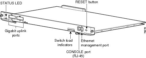
Figure 1-6 Supervisor Engine II-Plus (WS-X4013+)
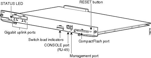
Figure 1-7 Catalyst 4500 Series Supervisor Engine II-Plus TS (WS-X4013+TS)
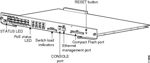
Figure 1-8 Supervisor Engine II-Plus 10GE (WS-X4013+10GE)
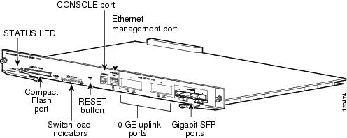
Figure 1-9 Supervisor Engine III (WS-X4014)
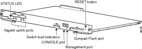
Figure 1-10 Supervisor Engine IV (WS-X4515)
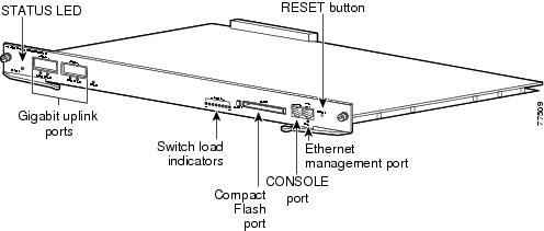
Figure 1-11 Supervisor Engine V (WS-X4516)
Figure 1-12 Supervisor Engine V-10GE (WS-X4516-10GE)
For information about the connectors, LEDs, and switches located on the front panel of the supervisor engine, see these sections:
•![]() LEDs
LEDs
•![]() Gigabit Ethernet Uplink Ports
Gigabit Ethernet Uplink Ports
LEDs
Table 1-6 describes the supervisor engine LEDs.
Gigabit Ethernet Uplink Ports
The Gigabit Ethernet uplink ports operate in full-duplex mode only. GBICs have SC connectors to interface with multimode fiber (MMF) and single-mode fiber (SMF) cable. For more information about GBICs, refer to the Catalyst 4500 Series Module Installation Guide.
When two Supervisor Engine Vs are present in a Catalyst 4507R and Catalyst 4510R, all four uplinks are active on both Primary (active) and Secondary (standby) supervisor engines by default, or two uplinks will be active in a nonredundant configuration. This limits access to slot 10 on the Catalyst 4510R to ports 3 and 4 only. You can only use the 2-port Gigabit Ethernet switching module (WS-X4302-GB) or the Access Gateway Module (WS-X4604-GWY) in slot 10 (flex-slot), when a Supervisor Engine V is used.
10-Gigabit Ethernet Uplink Ports
The 10-Gigabit Ethernet uplink ports operate in full-duplex mode only, and are only on the WS-X4516-10GE and WS-X4013+10GE. These ports use the hot-swappable 10GBASE X2 optical transceivers. The X2s have SC connectors to interface with multimode fiber (MMF) and single-mode fiber (SMF) cable.
On a Catalyst 4510R with a Supervisor Engine V-10GE, the user has the option to use either four Gigabit Ethernet uplinks using SFPs or two 10-Gigabit Ethernet uplinks using X2s. The user also has the option of using the Gigabit Ethernet and 10-Gigabit Ethernet uplinks simultaneously. With this option, the tenth slot can only support the WS-X4302-GB switching module. On a Catalyst 4507R, the user can use the Gigabit Ethernet uplinks and 10-Gigabit Ethernet uplinks simultaneously.
When two Supervisor Engine V-10GEs are present in a Catalyst 4510R or Catalyst 4507R switch, or two Supervisor Engine II-Plus 10GEs are present in a Catalyst 4507R, one X2 uplink is active on both the primary (active) and secondary (standby) supervisor engines by default, or two uplinks will be active in a nonredundant configuration.
SFP Ports
Gigabit Ethernet SFP ports operate in full-duplex mode only and are present on the WS-X4013+TS, WS-X4516-10GE and WS-X4013+10GE supervisors, as well as some switching modules. These ports use the 1000BASE-SX, 1000BASE-LX, Cisco Coarse Wave Division Multiplexing (CWDM ) SFPs, 1000BASE-T SFP, and 1000BASE-ZX SFP. SFP connectors vary with interface type and may use multimode fiber (MMF), single-mode fiber (SMF) cable, or copper Ethernet cables.
Ethernet Management Port
The Ethernet management port can be used (in ROMMON mode only) to recover a switch software image that has been corrupted or destroyed due to a network catastrophe. When using Cisco IOS Release 12.2(50)SG or later, this port can also perform the same functions as the console port. For earlier Cisco IOS software releases, this port is not active while the switch is operating normally.
CONSOLE Port
The CONSOLE port has an EIA/TIA-232 RJ-45 connector. The CONSOLE port allows you to perform the following functions:
•![]() Configure the switch from the CLI
Configure the switch from the CLI
•![]() Monitor network statistics and errors
Monitor network statistics and errors
•![]() Configure SNMP agent parameters
Configure SNMP agent parameters
Note ![]() EIA/TIA-232 was known as recommended standard RS-232 before its acceptance as a standard by the Electronic Industries Alliance (EIA) and Telecommunications Industry Association (TIA).
EIA/TIA-232 was known as recommended standard RS-232 before its acceptance as a standard by the Electronic Industries Alliance (EIA) and Telecommunications Industry Association (TIA).
RESET Button
The RESET button is used to restart the switch.
Note ![]() Use a paper clip or other small, pointed object to press the Reset button.
Use a paper clip or other small, pointed object to press the Reset button.
CompactFlash Port
The CompactFlash port accepts a Type 1 CompactFlash card. You can use it for file transfer tasks such as loading a new software image. The CompactFlash card is optional, and can be obtained from third-party suppliers.
For more information, refer to Using the Compact Flash on the Catalyst 4000 Family Supervisor Engine III and IV at the following URL:
http://www.cisco.com/en/US/docs/switches/lan/catalyst4500/hardware/configuration/notes/OL_2788.html
Fan Assembly
Note ![]() For complete environmental specifications, including airflow requirements, see "Specifications."
For complete environmental specifications, including airflow requirements, see "Specifications."
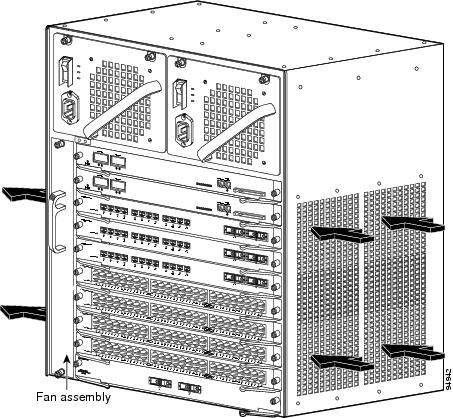
The system fan assembly provides cooling air for the internal chassis components. The fan assembly is a tray of fans that you can insert and remove from the chassis while the system is on line. The Catalyst 4503 fan assembly has two fans, the Catalyst 4506 fan assembly has four fans, the Catalyst 4507R fan assembly has six fans, and the Catalyst 4510R fan assembly has eight fans. The fans draw in fresh air from one side and exhaust air on the other side. Catalyst 4503 airflow is shown in Figure 1-13. Catalyst 4506 airflow is shown in Figure 1-14. Catalyst 4507R airflow is shown in Figure 1-15. Catalyst 4510R airflow is shown in Figure 1-16.

Figure 1-13 Catalyst 4503 Airflow
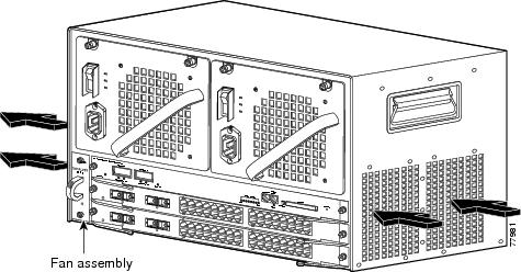
Figure 1-14 Catalyst 4506 Airflow
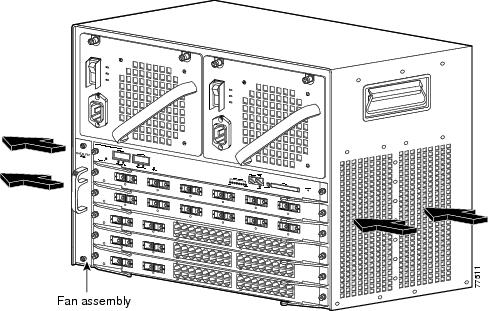
Figure 1-15 Catalyst 4507R Airflow
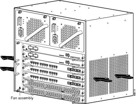
Figure 1-16 Catalyst 4510R Airflow
Power Supplies
Note ![]() For detailed specifications on all Catalyst 4500 series power supplies, refer to the "Catalyst 4500 Series Power Supplies" section.
For detailed specifications on all Catalyst 4500 series power supplies, refer to the "Catalyst 4500 Series Power Supplies" section.
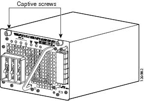
A Catalyst 4500 series switch can use a 1000 W, 1300 W, 1400 W, 2800 W (see Figure 1-17), or 4200 W (with two inputs, see Figure 1-18) AC-input power supply , a 1400 W DC-input power supply with integrated PEM (see Figure 1-19), or a 1400 W DC multiple-input power supply (see Figure 1-20). The power supplies are hot-swappable. If you have power supplies of different types installed in the two bays, only one will be active and some power features will not be available. The power supply in the left bay is PS1, the one in the right bay is PS2.
The AC-input power supply has a power cord that connects each power supply to the site power source. The DC-input power supply is equipped with a input terminal block that is directly connected to the site power wiring.
Each power supply has an ON/OFF switch that supplies power to the switch. For information on removing and replacing power supplies, see the "Removing and Replacing the Power Supply" section.
Figure 1-17 AC-Input Power Supply (All Except 4200 W)
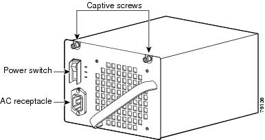
Figure 1-18 4200 W Dual Input AC Power Supply
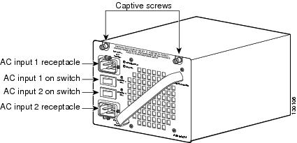
Note ![]() The 4200 W AC power supply should not be used in mixed-voltage configurations. All the inputs in a chassis must be the same voltage (110 or 220 V).
The 4200 W AC power supply should not be used in mixed-voltage configurations. All the inputs in a chassis must be the same voltage (110 or 220 V).
Figure 1-19 1400 W DC-Input Power Supply
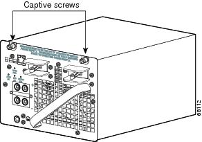
Figure 1-20 1400 W DC Triple-Input Power Supply
Note ![]() The 1400 W DC triple-input power supply is not compatible with other power supplies used on these products, and can only be used with similar supplies. In redundant mode, the two power supplies must have identical inputs. You will need to power down the switch to upgrade to or away from this power supply.
The 1400 W DC triple-input power supply is not compatible with other power supplies used on these products, and can only be used with similar supplies. In redundant mode, the two power supplies must have identical inputs. You will need to power down the switch to upgrade to or away from this power supply.
The 1400 W DC input power supply (either single or triple-input) may be used with the Catalyst 4500 Series AC Power Shelf. Documentation for the Catalyst 4500 Series AC Power Shelf is at http://www.cisco.com/en/US/docs/switches/lan/catalyst4500/hardware/configuration/notes/78_15068.html
Catalyst 4500 series switches support one power supply and an optional redundant power supply. Each AC power supply has an individual power cord and status LEDs. Systems with redundant power supplies will share the load, with each unit providing approximately one-half of the total load. For information about configuring your switch for redundant and combined modes, refer to the software configuration guide for your switch.
The Catalyst 4510R requires at least 1400 W of input power. (The 1000 W AC and 1300 W AC power supplies for the Catalyst 4500 series will fit and function in a Catalyst 4510R; however, power management may be required in high density configurations.) Cisco recommends the use of the 1400 W DC, 1400 W AC, and 2800 W AC power supplies for the Catalyst 4510R.
When power is removed from one power supply on a Catalyst 4500 series switch that has two power supplies, the redundant power feature causes the second power supply to produce full power.
To replace a power supply, see the "Removing and Replacing the Power Supply" section.
Power Supply LEDs
Table 1-7 describes the power supply LEDs.
Power Supply Fan
Each power supply has a built-in fan. Air enters the front of the power supply (power-input end) and exits through the back. An air dam keeps the airflow separate from the rest of the chassis, which is cooled by the system fan assembly.
Load-Sharing Feature
When you install and turn on a second power supply on a Catalyst 4500 series switch, it provides approximately one-half of the required power to the system. If one power supply fails, the other power supply immediately assumes full power to maintain uninterrupted system operation.
Note ![]() Load sharing works only when both power supplies in the chassis are the same type.
Load sharing works only when both power supplies in the chassis are the same type.
When you install a redundant power supply, load sharing and fault tolerance are enabled automatically; no additional software configuration is required.
Environmental Monitoring Feature
With the environmental monitoring and reporting feature, you can keep your system running by resolving adverse environmental conditions before loss of operation.
The power supply monitors its own internal temperature and voltages. In the event of excessive internal temperature, the power supply shuts down to prevent damage. When the power supply returns to a safe operating temperature, it restarts. If the power supply output voltage is not within the specified range, the LED labeled OUTPUT FAIL will light. An instance of substantial output overvoltage can shut down the power supply.
An instance of substantial input overvoltage (greater than -75 V DC continuous) can damage the power supply input circuitry and can cause it to shut down permanently.
For a 1400 W DC power supply, the main power switch has an input range of -40.5 to -72 V DC, while the -48 V PoE operates over a range of -40.5 to -56 V DC. The PoE either fails to start or shuts down if exposed to greater than -56 V DC input. PoE recovers after you recycle input power within the proper voltage range. If the PoE shuts down due to input overvoltage (greater than -56 V DC), the main converter section does not shut down.
The supervisor engine monitors the status of each power supply and provides a status report through the switch software. For more details on how the supervisor engine monitors the power supplies, refer to the "Environmental Monitoring and Power Management" chapter of the Catalyst 4500 Series Switch Cisco IOS Software Configuration Guide.
1400 W DC Triple-input Power Supply Operational Modes
The C4500 1400 W DC Triple Input SP Power Supply (data only) allows added redundancy by providing terminals for two DC inputs rated at 15 A and one rated at 12.5 A per power supply.
This power supply has five operational modes depending on the inputs receiving power. When all three inputs are active, at input voltages greater than -44.0 V DC, the power supply delivers 1400 W maximum total output. Table 1-8 provides output information for these modes, given a single supply.
The maximum total input current is 42.5A and the maximum ambient temperature is 55 C. To determine total maximum input power to a supply, add up the active individual module input power ratings. Table 1-9 provides output information for these modes, given two supplies working in combined mode. Table 1-10 provides output information for these modes, given two supplies working in redundant mode.
Note ![]() In a redundant configuration with all inputs supplied, there must be a 100 W minimum system load or the OUTPUT FAIL LED shows a false failure.
In a redundant configuration with all inputs supplied, there must be a 100 W minimum system load or the OUTPUT FAIL LED shows a false failure.
The C4500 1400 W DC Triple Input SP Power Supply requires a minimum draw from the system that it is installed in. Table 1-11 shows
System Architecture
This section describes the interaction between the various system components of Catalyst 4500 series switches. A Catalyst 4503 only is shown in the examples.
Power Flow
Figure 1-21 shows power ingress and flow through the system.
Figure 1-21 Power Flow
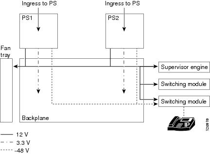
Power enters the switch through the power supplies. Several types of power supplies are available, depending on the power needs for your system and the power type available on your site. All power supplies provide a 3.3 V circuit (shown as a dash-dot line) to the components on the backplane and a 12 V circuit (shown as a solid line) that is carried over the backplane to the fans, supervisor engine, and switching modules. Power supplies that support PoE (1300 W AC, 2800 W AC, 4200 W AC or 1400 W DC) also provide a -48 V circuit (shown as a dashed line) to PoE-enabled switching modules, which is then available to the powered device connected to the switching module.
Note ![]() The Supervisor Engine II-Plus TS has internal DC-to-DC converters that use the 12 V circuit to provide PoE to powered devices connected to the Supervisor engine only. If your system has a Supervisor Engine II-Plus TS in slot 1, you still need a PoE-enabled power supply to provide PoE to the other slots.
The Supervisor Engine II-Plus TS has internal DC-to-DC converters that use the 12 V circuit to provide PoE to powered devices connected to the Supervisor engine only. If your system has a Supervisor Engine II-Plus TS in slot 1, you still need a PoE-enabled power supply to provide PoE to the other slots.
All Catalyst 4500 series switches support dual power supplies, configurable as combined mode or redundant mode. In combined mode, the switch has available the combined rated wattage of both power supplies, less some expected efficiency loss. In redundant mode, one power supply provides power to the system and the other supply is on standby should there be a failure in either the power supply or the input voltage source it is connected to.
Power over Ethernet
The Cisco Catalyst 4500 Series switches support the Cisco pre-standard and 802.3af standard for PoE on 10/100 or 10/100/1000 ports, enabling customers to support telephones, wireless base stations, video cameras, and other appliances. PoE makes it possible to place devices in unique locations without having to provide new outlets and costly electrical circuits. PoE also enables businesses to isolate critical devices on a single power system so that the entire system can be supported by uninterruptable power supply (UPS) backup.
All new Cisco Catalyst PoE line cards can support 15.4 W of power per port simultaneously. Not only do the cards support the IEEE standard, including the optional power classifications, but the Cisco pre-standard power implementation is also supported to help ensure backward compatibility with existing Cisco powered devices. The cards are compatible with any chassis and supervisor engine. Most importantly, the Catalyst 4500 series switch has the power supplies and accessories to support 15.4 W per port on every port simultaneously in any fully loaded chassis. (This requires an external power shelf or a 4200 W dual-input power supply.)
PoE Over-subscription
With the advent of powered devices requiring as much as 15.4 W and the different combinations of power supplies and chassis port densities, it becomes quite possible to over-subscribe the PoE capacity of the power supplies. This temporary over-subscription typically occurs when a power supply configured in combined mode fails or when the user has not kept track of the powered devices and plugs in one too many. The best practice is to design a PoE system in which all devices receive the power needed at all times. When a power supply is over-subscribed—more power is being drawn from it than it can supply—the power supply shuts down. There are several ways to predictably manage a temporary PoE over-subscription:
1. ![]() Configure unused ports to never receive PoE. This prevents a user from inadvertently plugging a powered device into a port and causing problems for other powered devices.
Configure unused ports to never receive PoE. This prevents a user from inadvertently plugging a powered device into a port and causing problems for other powered devices.
2. ![]() Configure ports to be in static mode. This is for ports that have highest priority, such as phones for executives or wireless access points. If ports need to be disabled because of a power shortage, auto ports are disabled before static ports.
Configure ports to be in static mode. This is for ports that have highest priority, such as phones for executives or wireless access points. If ports need to be disabled because of a power shortage, auto ports are disabled before static ports.
3. ![]() Configure the maximum wattage on ports to be less than the default, based on the maximum power consumption of the powered device. This disallows devices demanding unexpected amounts of power and also stretches the finite resources of the power supplies. For example, the default port wattage is 15.4 W. By configuring a maximum of 7 W, twice as many PoE powered devices can be supported with the same power supply.
Configure the maximum wattage on ports to be less than the default, based on the maximum power consumption of the powered device. This disallows devices demanding unexpected amounts of power and also stretches the finite resources of the power supplies. For example, the default port wattage is 15.4 W. By configuring a maximum of 7 W, twice as many PoE powered devices can be supported with the same power supply.
PoE Line Cards
The Cisco Catalyst 4500 series offers line cards, power supplies, and accessories required to deploy and operate a standards-based PoE internetwork. PoE provides -48 V DC power over standard Category 5 unshielded twisted-pair (UTP) cable up to 100 meters when an IEEE 802.3af-compliant or Cisco pre-standard powered device is attached to the PoE line card port. Instead of requiring wall power, attached devices such as IP phones, wireless base stations, video cameras, and other IEEE-compliant appliances can use power provided by the PoE line cards. This capability gives network administrators centralized control over power and eliminates the need to install outlets in ceilings and other out-of-the-way places where a powered device may be installed.
Although references to "PoE," "inline-power," and "voice" power supplies and line cards are synonymous, there are only two versions: Cisco prestandard and IEEE 802.3af compliant. Every Cisco Catalyst 4500 series chassis and PoE power supply supports the IEEE 802.3af standard and the Cisco prestandard power implementation ensuring backward compatibility with existing Cisco powered devices. All IEEE 802.3af-compliant line cards can distinguish an IEEE or Cisco prestandard powered device from an unpowered network interface card (NIC), ensuring that power is applied only when an appropriate device is connected.
All PoE line cards can distinguish an IEEE or Cisco prestandard powered device from an unpowered network interface card (NIC) to ensure power is applied only when an appropriate device is connected. With a Cisco PoE network, administrators can depend on a robust network that is safe to deploy and simple to maintain.
Deploying PoE on the Cisco Catalyst 4500 Series
When the switch is properly configured, implementing PoE is easy when it is used with a Cisco powered device that supports Cisco Discovery Protocol. All PoE line cards automatically detect an attached powered device the moment it is installed. Also, the switch returns unused port power to the system power budget for use by other devices because it supports the IEEE802.3af optional power classifications.
The Cisco Catalyst 4500 series offers internal power supplies and external power devices for multiple deployment scenarios. These scenarios include small and large deployments in AC or DC environments for data-only configurations, and scalability of up to 15.4 W per port for PoE configurations.
The switches share a common power supply form factor. Each Cisco Catalyst 4500 Series chassis is designed for 1 + 1 power protection while meeting the needs of PoE demands. In addition to power resiliency, the Cisco Catalyst 4500 Series includes 1 + 1 supervisor-engine redundancy (Cisco Catalyst 4507R and Catalyst 4510R only) and software-based fault tolerance. Integrated resiliency in both hardware and software minimizes network downtime, helping ensure workforce productivity, portability, and customer success.
All available Cisco Catalyst 4500 Series power supplies can be used for data-only deployments, which typically require just a few hundred watts. For deployments that dictate support for PoE power, Cisco offers several options.
The Cisco Catalyst 4500 Series offers several internal supplies: 1000 W AC (data only), 1400 W AC (data only), 1300 W (data and PoE), 1400 W DC (data and PoE), 2800 W (data and PoE), and 4200 W AC (data and PoE). When more than 4200 W of redundant data and PoE are required for a Cisco Catalyst 4500 Series chassis in an AC-powered environment, Cisco offers an external AC power shelf that houses two 2500 W AC power supplies. When two power shelves are combined, they can produce 7500 W—the remaining 2500 W supply can be used for N + 1 protection.
The Cisco Catalyst 4500 Series has two DC power options; one is optimized for data-only deployments in service provider central offices (part number PWR-C45-1400DC), and the other is used for high-power PoE deployments (part number PWR-C45-1400DC-P).
Cisco Catalyst 4500 Series External AC Power Shelf and
1400 W DC Power Supply with Integrated Power Entry Module
The external AC power shelf must be used in conjunction with the 1400 W DC power supply. In addition to providing power for the chassis, fans, and non-PoE line cards, the 1400 W DC power supply contains a power entry module (PEM). The PEM is used to pass additional power to the chassis backplane, power demanded by the PoE line cards. The chassis power trace used for PoE is independent from the one used by the supervisor engine(s), fan tray, and backplane components. The 1400 W DC power supply can accept up to 7500 W DC for data and PoE applications. Up to 1400 W can be dedicated for data (supervisor engine, fan tray, etc.), while the remaining power is passed through via the PEM and is used for PoE.
When only one external AC power shelf is used (with two 2500 W AC power supplies), it provides the 1400 W DC power supply with 5000 W of DC power in total. When two AC power shelves are strapped together, the switch can provide up to 7500 W of DC power (3 + 1 redundant).
Cisco Catalyst 4500 Series Service Provider DC Power Supply
The triple-input 1400 W DC power supply is optimized for service provider or central-office deployments. By providing multiple inputs, the service provider DC power supply enables central-office technicians to customize the output power to meet their application needs. Many central-office deployments require only a fraction of the 1400 W available in the service provider power supply. Low current inputs mean technicians can connect the supply to smaller fuses and breakers. The service provider power supply makes it possible to deploy a Cisco Catalyst 4503 with a single 15A circuit. Likewise, it is possible to deploy a fully populated Cisco Catalyst 4510R with two 20A and one 15A circuits rather than a single 60A connection, which often requires rack rewiring.
Management Flow
Figure 1-22 shows management and status information flow through the system.
Figure 1-22 Management Flow
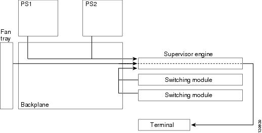
Each system component has an EEPROM that identifies it to the supervisor engine over a serial connection on the backplane, which also passes along information like temperature, fan speed, power draw per slot and port, and port activity. LED status information is also sent to the supervisor engine, which makes it available to an administrator through a terminal connection or management software.
All Catalyst 4500 series switches support:
•![]() Hardware-based multicast-Protocol Independent Multicast (PIM).
Hardware-based multicast-Protocol Independent Multicast (PIM).
•![]() Internet Group Management Protocol (IGMP).
Internet Group Management Protocol (IGMP).
•![]() Cisco Group Management Protocol support standards-based and Cisco technology-enhanced efficient multimedia networking.
Cisco Group Management Protocol support standards-based and Cisco technology-enhanced efficient multimedia networking.
•![]() Simple Network Management Protocol (SNMP).
Simple Network Management Protocol (SNMP).
•![]() CiscoWorks, which can manage critical network characteristics such as availability, responsiveness, resilience, and security.
CiscoWorks, which can manage critical network characteristics such as availability, responsiveness, resilience, and security.
•![]() Cisco NetFlow Services. The Cisco NetFlow Services Card for the Supervisor Engine IV and V support statistics capture in hardware for flow-based and VLAN-based statistics monitoring. This data can be exported, collected, and analyzed for virus detection and mitigation, network-traffic accounting, usage-based network billing, network planning, network monitoring, and data-mining capabilities. Cisco NetFlow Services is integral to the Supervisor Engine V-10GE.
Cisco NetFlow Services. The Cisco NetFlow Services Card for the Supervisor Engine IV and V support statistics capture in hardware for flow-based and VLAN-based statistics monitoring. This data can be exported, collected, and analyzed for virus detection and mitigation, network-traffic accounting, usage-based network billing, network planning, network monitoring, and data-mining capabilities. Cisco NetFlow Services is integral to the Supervisor Engine V-10GE.
Switching Traffic Flow
Figure 1-23 shows switching traffic flow through the system.
Figure 1-23 Switching Traffic Flow
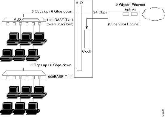
Frames flow into the switch through interfaces on the switching modules. Each switching module connects to a mux/buffer on the backplane that supports a connection of up to 6 Gbps up (Tx) to the supervisor engine and 6 Gbps from (Rx) the supervisor engine. When a frame reaches the supervisor engine, it is examined and either sent out of an interface in one of the other slots, or out of the uplink on the supervisor engine.
Over-subscription
Switching modules that have 24 or 48 Gigabit Ethernet (1000BASE-T) ports over-subscribe on a Catalyst 4500 switch by grouping the ports with an additional mux/buffer on the switching module, which creates a single, nonblocking, full-duplex Gigabit Ethernet connection to the internal switch fabric. For each group of ports, frames received are buffered and sent to the common Gigabit Ethernet link to the internal switch fabric. If the amount of data received for a port begins to exceed buffer capacity, flow control sends pause frames to the remote port to temporarily stop traffic and prevent frame loss.
Each port in the group shares the bandwidth of a Gigabit Ethernet link. However, each port operates independently so that flow control, or configuration of one port, does not block or degrade the performance of another port in that group. Switching modules that have up to six 1000BASE-T ports do not use over-subscription.
The amount of over-subscription can be controlled by varying the number of ports used at 1000 Mbps. All ports can use Cisco Gigabit EtherChannel technology or IEEE 802.3ad for high-speed interconnection applications. All over-subscribed ports use the standard IEEE 802.1x flow control (PAUSE frame) mechanism to control Gigabit Ethernet host traffic.
Supervisor Redundancy
The Cisco Catalyst 4507R and Catalyst 4510R switches support 1+1 supervisor-engine redundancy for integrated resiliency. Redundant supervisor engines help minimize network downtime. With the support of stateful switchover (SSO), the secondary supervisor engine serves as a backup to immediately take over after a primary supervisor failure. During the switchover, Layer 2 links are maintained transparently without the need to renegotiate sessions. As a result, business-critical applications such as Voice-over-IP (VoIP) calls are not dropped. The Nonstop Forwarding (NSF) Aware feature in Cisco IOS software is also supported, providing the ability to interface with NSF-capable devices and to continue forwarding packets as routing information is updated upon a supervisor-engine switchover.
 Feedback