Catalyst 4500 Series Supervisor Engines and Switching Modules Installation Note
Available Languages
Table of Contents
Catalyst 4500 Series Supervisor Engines and Switching Modules Installation Note
Installing Supervisor Engines and Switching Modules
Standards Compliance Specifications
Obtaining Documentation and Submitting a Service Request
Catalyst 4500 Series Supervisor Engines and Switching Modules Installation Note
This publication describes how to install and verify the operation of the Catalyst 4500 series and Catalyst 4500 E- series supervisor engines and switching modules. For configuration information for the supervisor engines and switching modules, refer to the Software Configuration Guide for your switch.

Note![]() Catalyst 4500 E-series switching modules require the Catalyst 4500 Series Supervisor Engine VI, which requires Cisco IOS Release 12.2(40)SG or later.
Catalyst 4500 E-series switching modules require the Catalyst 4500 Series Supervisor Engine VI, which requires Cisco IOS Release 12.2(40)SG or later.
Safety Overview
Throughout this publication, safety warnings appear in procedures that may harm you if performed incorrectly. A warning symbol precedes each warning statement.


Warning![]() Only trained and qualified personnel should be allowed to install, replace, or service this equipment. Statement 1030
Only trained and qualified personnel should be allowed to install, replace, or service this equipment. Statement 1030
Installing Supervisor Engines and Switching Modules
All Catalyst 4500 series switches support hot swapping, which lets you install, remove, replace, and rearrange switching modules without turning off the system power. When the system detects that a switching module has been installed or removed, it runs diagnostic and discovery tests automatically, acknowledges the presence or absence of the module, and resumes system operation with no operator intervention.
This section describes the following topics:
Required Tools
You will need these tools to install supervisor engines and switching modules in the Catalyst 4500 series switches:
- Number 1 and number 2 Phillips screwdrivers for the captive installation screws on most modules
- 3/16-inch flat-blade screwdriver for the captive installation screws on other modules
- Antistatic mat or antistatic foam
- Wrist strap or other grounding device
Note![]() Whenever you handle switching modules, use a wrist strap or other grounding device to prevent ESD damage.
Whenever you handle switching modules, use a wrist strap or other grounding device to prevent ESD damage.
Removing Switching Modules
Warning![]() Invisible laser radiation may be emitted from disconnected fibers or connectors. Do not stare into beams or view directly with optical instruments. Statement 1051
Invisible laser radiation may be emitted from disconnected fibers or connectors. Do not stare into beams or view directly with optical instruments. Statement 1051
Warning![]() Hazardous voltage or energy is present on the backplane when the system is operating. Use caution when servicing. Statement 1034
Hazardous voltage or energy is present on the backplane when the system is operating. Use caution when servicing. Statement 1034
Warning![]() Voltages that present a shock hazard may exist on Power over Ethernet (PoE) circuits if interconnections are made using uninsulated exposed metal contacts, conductors, or terminals. Avoid using such interconnection methods, unless the exposed metal parts are located within a restricted access location and users and service people who are authorized within the restricted access location are made aware of the hazard. A restricted access area can be accessed only through the use of a special tool, lock and key or other means of security. Statement 1072
Voltages that present a shock hazard may exist on Power over Ethernet (PoE) circuits if interconnections are made using uninsulated exposed metal contacts, conductors, or terminals. Avoid using such interconnection methods, unless the exposed metal parts are located within a restricted access location and users and service people who are authorized within the restricted access location are made aware of the hazard. A restricted access area can be accessed only through the use of a special tool, lock and key or other means of security. Statement 1072

To remove a switching module from a Catalyst 4500 series switch, follow this procedure:
Step 1![]() Disconnect any network interface cables attached to the ports on the switching module that you intend to remove.
Disconnect any network interface cables attached to the ports on the switching module that you intend to remove.
Step 2![]() Loosen the captive installation screws. (See Figure 1.)
Loosen the captive installation screws. (See Figure 1.)
Figure 1 Captive Installation Screws and Ejector Levers
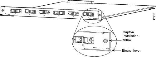
Step 3![]() Grasp the left and right ejector levers, and simultaneously pivot the levers outward to release the switching module from the backplane connector. Figure 1 shows a close-up view of the right ejector lever.
Grasp the left and right ejector levers, and simultaneously pivot the levers outward to release the switching module from the backplane connector. Figure 1 shows a close-up view of the right ejector lever.
Step 4![]() Grasp the front panel of the switching-module with one hand, and place your other hand under the carrier to support and guide it out of the slot. Do not touch the printed circuit boards or connector pins.
Grasp the front panel of the switching-module with one hand, and place your other hand under the carrier to support and guide it out of the slot. Do not touch the printed circuit boards or connector pins.
Step 5![]() Carefully pull the switching module straight out of the slot, keeping your other hand under the carrier to guide it.
Carefully pull the switching module straight out of the slot, keeping your other hand under the carrier to guide it.
Step 6![]() Place the switching module on an antistatic mat or antistatic foam, or immediately install it in another slot.
Place the switching module on an antistatic mat or antistatic foam, or immediately install it in another slot.
Step 7![]() If the slot is to remain empty, install a switching-module filler plate (part number 800-00292-01) or a blank card if installing a Catalyst 4500 E-series chassis.
If the slot is to remain empty, install a switching-module filler plate (part number 800-00292-01) or a blank card if installing a Catalyst 4500 E-series chassis.
Warning![]() Blank faceplates and cover panels serve three important functions: they prevent exposure to hazardous voltages and currents inside the chassis; they contain electromagnetic interference (EMI) that might disrupt other equipment; and they direct the flow of cooling air through the chassis. Do not operate the system unless all cards, faceplates, front covers, and rear covers are in place. Statement 1029
Blank faceplates and cover panels serve three important functions: they prevent exposure to hazardous voltages and currents inside the chassis; they contain electromagnetic interference (EMI) that might disrupt other equipment; and they direct the flow of cooling air through the chassis. Do not operate the system unless all cards, faceplates, front covers, and rear covers are in place. Statement 1029
Installing Switching Modules
All Catalyst 4500 series supervisor engine modules and switching modules are installed in horizontal chassis slots that are numbered from top to bottom.
Warning![]() Invisible laser radiation may be emitted from disconnected fibers or connectors. Do not stare into beams or view directly with optical instruments. Statement 1051
Invisible laser radiation may be emitted from disconnected fibers or connectors. Do not stare into beams or view directly with optical instruments. Statement 1051
Warning![]() Voltages that present a shock hazard may exist on Power over Ethernet (PoE) circuits if interconnections are made using uninsulated exposed metal contacts, conductors, or terminals. Avoid using such interconnection methods, unless the exposed metal parts are located within a restricted access location and users and service people who are authorized within the restricted access location are made aware of the hazard. A restricted access area can be accessed only through the use of a special tool, lock and key or other means of security. Statement 1072
Voltages that present a shock hazard may exist on Power over Ethernet (PoE) circuits if interconnections are made using uninsulated exposed metal contacts, conductors, or terminals. Avoid using such interconnection methods, unless the exposed metal parts are located within a restricted access location and users and service people who are authorized within the restricted access location are made aware of the hazard. A restricted access area can be accessed only through the use of a special tool, lock and key or other means of security. Statement 1072
To install a switching module in a Catalyst 4500 series switch, follow this procedure:
Step 1![]() Take the necessary precautions to prevent ESD damage as described in the Regulatory Compliance and Safety document that accompanied your switch.
Take the necessary precautions to prevent ESD damage as described in the Regulatory Compliance and Safety document that accompanied your switch.
Step 2![]() Choose a slot for the new switching module. Ensure that you have enough clearance to accommodate any interface equipment that you will connect directly to the switching module ports. If possible, place switching modules between empty slots that contain only switching-module filler plates.
Choose a slot for the new switching module. Ensure that you have enough clearance to accommodate any interface equipment that you will connect directly to the switching module ports. If possible, place switching modules between empty slots that contain only switching-module filler plates.
Step 3![]() Loosen the captive installation screws that secure the switching-module filler plate (or the existing switching module) to the desired slot.
Loosen the captive installation screws that secure the switching-module filler plate (or the existing switching module) to the desired slot.
Step 4![]() Remove the switching-module filler plate (or the existing switching module). Save the switching-module filler plate for future use. If you are removing an existing switching module, see the “Removing Switching Modules” section.
Remove the switching-module filler plate (or the existing switching module). Save the switching-module filler plate for future use. If you are removing an existing switching module, see the “Removing Switching Modules” section.
Step 5![]() To install the new switching module, grasp the switching-module front panel with one hand, and place your other hand under the carrier to support the switching module, as shown in Figure 2. Do not touch the printed circuit boards or connector pins.
To install the new switching module, grasp the switching-module front panel with one hand, and place your other hand under the carrier to support the switching module, as shown in Figure 2. Do not touch the printed circuit boards or connector pins.
Step 6![]() Align the edges of the circuit board with the slot guides on the sides of the switch chassis, as shown in Figure 2.
Align the edges of the circuit board with the slot guides on the sides of the switch chassis, as shown in Figure 2.
Figure 2 Installing the Switching Module in the Chassis

Step 7![]() Pivot the two module ejector levers out and away from the faceplate.
Pivot the two module ejector levers out and away from the faceplate.
Step 8![]() Carefully slide the switching module into the slot until the notches on both ejector levers engage the chassis sides.
Carefully slide the switching module into the slot until the notches on both ejector levers engage the chassis sides.
Step 9![]() Using the thumb and forefinger of each hand, simultaneously pivot in both ejector levers to fully seat the switching module in the backplane connector.
Using the thumb and forefinger of each hand, simultaneously pivot in both ejector levers to fully seat the switching module in the backplane connector.
Step 10![]() Use a screwdriver to tighten the captive installation screws on each end of the switching module faceplate.
Use a screwdriver to tighten the captive installation screws on each end of the switching module faceplate.
To check the status of the module, follow this procedure:
Step 1![]() Ensure that the STATUS LED is green (module operational).
Ensure that the STATUS LED is green (module operational).
Step 2![]() When the switch is online, enter the show module command. Verify that the system acknowledges the new module and that the module’s status is listed as good in the command output.
When the switch is online, enter the show module command. Verify that the system acknowledges the new module and that the module’s status is listed as good in the command output.
Step 3![]() If the module is not operational, reseat it. If the module is still not operational, contact your customer service representative.
If the module is not operational, reseat it. If the module is still not operational, contact your customer service representative.
Standards Compliance Specifications
For information about standards compliance on Catalyst 4500 series products, please refer to Regulatory Compliance and Safety Information for the Catalyst 4500 Series Switches.
Related Documentation
For more detailed installation and configuration information, refer to the following:
- Catalyst 4500 Series Module Installation Guide
- Catalyst 4500 Series Installation Guide
- Catalyst 4500 E-Series Installation Guide
- Regulatory Compliance and Safety Information for the Catalyst 4500 Series Switches
- Catalyst 4500 Series Switch Cisco IOS Command Reference
- Catalyst 4500 Series Switch Cisco IOS System Message Guide
- Catalyst 4500 Series Switch Cisco IOS Configuration Guide
- Release Notes for the Catalyst 4500 Series Switches
Obtaining Documentation and Submitting a Service Request
For information on obtaining documentation, submitting a service request, and gathering additional information, see the monthly What’s New in Cisco Product Documentation, which also lists all new and revised Cisco technical documentation, at:
http://www.cisco.com/en/US/docs/general/whatsnew/whatsnew.html
Subscribe to the What’s New in Cisco Product Documentation as a Really Simple Syndication (RSS) feed and set content to be delivered directly to your desktop using a reader application. The RSS feeds are a free service and Cisco currently supports RSS version 2.0.
This document is to be used in conjunction with the publications documents that support your specific Cisco device.
CCVP, the Cisco logo, and Welcome to the Human Network are trademarks of Cisco Systems, Inc.; Changing the Way We Work, Live, Play, and Learn is a service mark of Cisco Systems, Inc.; and Access Registrar, Aironet, BPX, Catalyst, CCDA, CCDP, CCIE, CCIP, CCNA, CCNP, CCSP, Cisco, the Cisco Certified Internetwork Expert logo, Cisco IOS, Cisco Press, Cisco Systems, Cisco Systems Capital, the Cisco Systems logo, Cisco Unity, Enterprise/Solver, EtherChannel, EtherFast, EtherSwitch, Fast Step, Follow Me Browsing, FormShare, GigaDrive, HomeLink, Internet Quotient, IOS, iPhone, IP/TV, iQ Expertise, the iQ logo, iQ Net Readiness Scorecard, iQuick Study, LightStream, Linksys, MeetingPlace, MGX, Networkers, Networking Academy, Network Registrar, PIX, ProConnect, ScriptShare, SMARTnet, StackWise, The Fastest Way to Increase Your Internet Quotient, and TransPath are registered trademarks of Cisco Systems, Inc. and/or its affiliates in the United States and certain other countries.
 Feedback
Contact Cisco
- Open a Support Case

- (Requires a Cisco Service Contract)