Catalyst 3850 Switch Getting Started Guide
Available Languages
Table of Contents
Catalyst 3850 Switch Getting Started Guide
Installation Warning Statements
Securing the AC Power Cord (Optional)
Connecting the StackWise Cables
StackWise Cabling Configurations
Connecting the StackPower Cables (Optional)
StackPower Cabling Configurations
Installing the Network Module (Optional)
10/100/1000, 10/100/1000 PoE+, or 10/100/1000 Cisco UPOE Ports
SFP and SFP+ Tranceiver Module Ports
Obtaining Documentation and Submitting a Service Request
Catalyst 3850 Switch Getting Started Guide
- About This Guide
- Shipping Box Contents
- Running Express Setup
- Managing the Switch
- Installing the Switch
- Securing the AC Power Cord (Optional)
- Connecting the StackWise Cables
- Connecting the StackPower Cables (Optional)
- Installing the Network Module (Optional)
- Connecting the Switch Ports
- Troubleshooting
- Obtaining Documentation and Submitting a Service Request
- Related Documentation
About This Guide
This guide describes how to use Express Setup to initially configure your Catalyst 3850 switch. The guide also covers switch management options, basic rack-mounting, stacking, port and module connections, and troubleshooting.
For more installation and configuration information, see the Catalyst 3850 documentation on Cisco.com. For system requirements, important notes, limitations, open and resolved bugs, and documentation updates, see the release notes on Cisco.com.
When using the online publications, refer to the documents that match the Cisco IOS software version running on the switch.
For translations of the warnings that appear in this publication, see the Regulatory Compliance and Safety Information for the Catalyst 3850 Switch on Cisco.com.

Note![]() The illustrations of the Catalyst 3850 switch are not intended to depict any particular color scheme. They are provided as a reference for various features and markings described within this guide.
The illustrations of the Catalyst 3850 switch are not intended to depict any particular color scheme. They are provided as a reference for various features and markings described within this guide.
Shipping Box Contents
The shipping box contains the model of the switch you ordered and other components needed for installation, as shown in Figure 1. Some components are optional, depending on your order.
Note![]() Verify that you have received these items. If any item is missing or damaged, contact your Cisco representative or reseller for instructions.
Verify that you have received these items. If any item is missing or damaged, contact your Cisco representative or reseller for instructions.
Figure 1 Components delivered in the shipping box
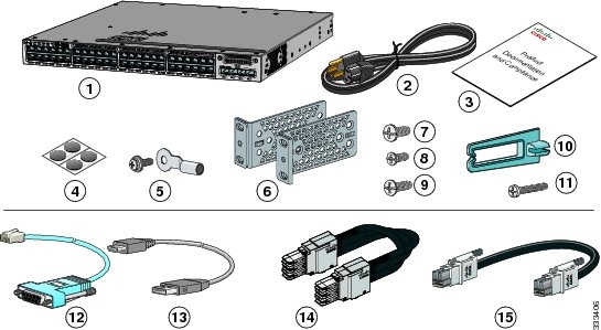
Catalyst 3850-48P-L1 switch with optional network module2 (power supply and fan modules not shown)3 |
|||
(Optional) RJ-45 console cable 2 |
|||
(Optional) USB console cable 2 |
|||
(Optional) StackWise cable (0.5-meter, 1-meter, or 3-meter) 2 |
|||
(Optional) StackPower cable (0.3-meter or 1.5-meter) 2 |
|||
Running Express Setup
Use Express Setup to enter the initial IP information. This action enables the switch to connect to local routers and the Internet. You can access the switch through the IP address for further configuration.
To use the CLI-based initial setup program, see Appendix C, “Configuring the Switch with the CLI-Based Setup Program,” in the switch hardware guide.
Note![]() If you are using Cisco IOS XE Denali 16.1.1 and later releases, see the “Configuring the Switch” section of the Catalyst 3850 Switch Hardware Installation Guide, for information about setting up the switch. Express Setup is not supported on Cisco IOS XE Denali 16.1.1 and later releases.
If you are using Cisco IOS XE Denali 16.1.1 and later releases, see the “Configuring the Switch” section of the Catalyst 3850 Switch Hardware Installation Guide, for information about setting up the switch. Express Setup is not supported on Cisco IOS XE Denali 16.1.1 and later releases.
- PC or laptop with Windows Vista, XP, or 2000
- Browser (Internet Explorer 5.5, 6.0, 7.0, Firefox 1.5, 2.0, and 3.0) with JavaScript enabled
- Straight-through or crossover Category 5 Ethernet cable
Note![]() Before running Express Setup, disable any pop-up blockers or proxy settings in your browser and any wireless client running on your PC or laptop.
Before running Express Setup, disable any pop-up blockers or proxy settings in your browser and any wireless client running on your PC or laptop.
|
||
| During Express Setup, the switch acts as a DHCP server. If your PC or laptop has a static IP address, temporarily change your PC or laptop settings before you use DHCP. Note Write down the static IP address. You will need this IP address in Step 14. |
||
| Install the power supply modules. See the “Power Supply Installation” chapter in the Catalyst 3850 Switch Hardware Installation Guide for instructions. |
||
| AC power switches: Plug the AC power cord into the switch power supply and into a grounded AC outlet. DC power switches: See the wiring instructions in the Catalyst 3850 Switch Hardware Installation Guide on Cisco.com: |
|
|
| Observe the POST results. Approximately 30 seconds after the switch powers on, it begins the power-on self-test (POST), which can take up to 5 minutes to complete. During POST, the SYSTEM LED blinks green. When POST is complete, the SYSTEM LED turns solid green. The ACTV LED is green if the switch is acting as the active switch. Note Before going to the next step, wait until POST is complete. If the SYST LED does not turn solid green, or turns amber, the switch failed the POST. Contact your Cisco representative or reseller. |
||
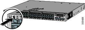
Press and hold the Mode button until all the LEDs next to the Mode button turn green. You might need to hold the button for more than 3 seconds. The switch is now in Express Setup mode. If the LEDs next to the Mode button blink when you press the button, release it. Blinking LEDs mean that the switch is already configured and cannot go into Express Setup mode. For more information, see the “Resetting the Switch” section. |
|
|
Connect a Category 5 Ethernet cable to a port:
Connect the other end of the cable to the Ethernet port on your PC or laptop. Wait until the port LEDs on the switch and your PC or laptop or laptop are green or blinking green. Green LEDs indicate a successful connection. If the port LEDs do not turn green after about 30 seconds, make sure that: |

|
|
| Start a browser session on the PC or laptop, and enter the IP address https:// 10.0.0.1. When prompted, enter the default password, cisco. Note The switch ignores text in the username field. The Express Setup window appears. If the Express Setup window does not appear, make sure that any browser pop-up blockers or proxy settings are disabled and that any wireless client is disabled on your PC or laptop. |
||
| Enter this information in the Network Settings fields: Note All entries must be in English letters. Note We recommend that you use the default VLAN value. During Express Setup, VLAN 1 is the only VLAN on the switch. Enter a new VLAN ID only if you want to change the management interface through which you manage the switch. The VLAN ID range is 1 to 1001.
Note You must change the default password, cisco. (Optional) Enter this information in the Ethernet Management Port Settings fields: |
||
| (Optional) You can enter the Optional Settings information now or enter it later by using the Device Manager interface. You can enter other administrative settings in the Optional Settings fields. For example, the optional administrative settings identify and synchronize the switch for enhanced management. NTP automatically synchronizes the switch clock with the network clock. You can manually set the system clock if the switch should have different settings. |
||
| (Optional) You can select the Advanced Settings tab on the Express Setup window and enter the advanced settings now or enter them later by using the Device Manager interface.
Note Enabling IPv6 restarts the switch when you complete Express Setup. |
||
| Click Submit to save your changes and to complete the initial setup.
For more information about Express Setup fields, see the online help for the Express Setup window. |
||
| Disconnect the switch from the PC or laptop, and install the switch in your network. See the “Installing the Switch” section. |
||
| If you changed the static IP address on your PC or laptop in Step 2, change it to the previously configured static IP address. |
||
| See the “Managing the Switch” section for information about configuring and managing the switch. |
||
| 1. 2. If Device Manager does not appear:
When the LED on the switch port connected to the PC or laptop is green, reenter the IP address of the switch in a browser to display Device Manager. When Device Manager appears, you can continue with the configuration. |
||
Managing the Switch
After completing Express Setup and installing the switch in your network, you can use these options for configuration:
Device Manager
The simplest way to manage the switch is by using Device Manager in the switch memory. This is a web interface that offers quick configuration and monitoring. You can access it through a web browser.
1.![]() Launch a web browser on your PC or laptop.
Launch a web browser on your PC or laptop.
2.![]() Enter the switch IP address in the web browser, and press Enter. The Device Manager page appears.
Enter the switch IP address in the web browser, and press Enter. The Device Manager page appears.
3.![]() Use Device Manager for basic switch configuration and monitoring. Refer to the Device Manager online help for more information.
Use Device Manager for basic switch configuration and monitoring. Refer to the Device Manager online help for more information.
Configuration Wizard
The Configuration Wizard is a Web-based controller user interface (UI) that lets you complete the initial wireless configuration after you configure the IP address, local username, and password or authorization using the authentication server. Using the Web UI, you can configure the controller, WLAN, and radios for all initial operations, establish management parameters, set security policies, access software management commands, configure system logs, and other tasks.
For more information on using the Configuration Wizard, see the switch software configuration guide on Cisco.com
Command-Line Interface
You can enter Cisco IOS commands and parameters through the CLI by using one of these options:
Note![]() You cannot use the RJ-45 console port and the USB console port at the same time. The USB console port takes precedence over the RJ-45 port when both are connected.
You cannot use the RJ-45 console port and the USB console port at the same time. The USB console port takes precedence over the RJ-45 port when both are connected.
USB Console Port
Note![]() If you are connecting a Microsoft Windows-based PC or laptop to the switch USB console port, install a USB device driver before you connect for the first time. See the Catalyst 3850 Switch Hardware Installation Guide for instructions.
If you are connecting a Microsoft Windows-based PC or laptop to the switch USB console port, install a USB device driver before you connect for the first time. See the Catalyst 3850 Switch Hardware Installation Guide for instructions.
Step 1![]() Connect a USB cable to the PC or laptop USB port. Connect the other end of the cable to the mini-B (5-pin-connector) USB port on the switch front panel.
Connect a USB cable to the PC or laptop USB port. Connect the other end of the cable to the mini-B (5-pin-connector) USB port on the switch front panel.
Step 2![]() Start a terminal-emulation program on the PC or laptop.
Start a terminal-emulation program on the PC or laptop.
Step 3![]() Configure the PC or laptop terminal emulation software for 9600 baud, 8 data bits, no parity, 1 stop bit, and no flow control.
Configure the PC or laptop terminal emulation software for 9600 baud, 8 data bits, no parity, 1 stop bit, and no flow control.
Step 4![]() Use the CLI to configure the switch. See the Catalyst 3850 Switch Software Configuration Guide and the Catalyst 3850 Switch Command Reference.
Use the CLI to configure the switch. See the Catalyst 3850 Switch Software Configuration Guide and the Catalyst 3850 Switch Command Reference.
RJ-45 Console Port
Step 1![]() Connect the RJ-45-to-DB-9 adapter cable to the 9-pin serial port on the PC or laptop. Connect the other end of the cable to the switch console port on the rear panel.
Connect the RJ-45-to-DB-9 adapter cable to the 9-pin serial port on the PC or laptop. Connect the other end of the cable to the switch console port on the rear panel.
Step 2![]() Start a terminal-emulation program on the PC or laptop.
Start a terminal-emulation program on the PC or laptop.
Step 3![]() Configure the PC or laptop terminal emulation software for 9600 baud, 8 data bits, no parity, 1 stop bit, and no flow control.
Configure the PC or laptop terminal emulation software for 9600 baud, 8 data bits, no parity, 1 stop bit, and no flow control.
Step 4![]() Use the CLI to configure the switch. See the Catalyst 3850 Switch Software Configuration Guide and the Catalyst 3850 Switch Command Reference.
Use the CLI to configure the switch. See the Catalyst 3850 Switch Software Configuration Guide and the Catalyst 3850 Switch Command Reference.
Ethernet Management Port
Step 1![]() Connect a Category 5 Ethernet cable to the PC or laptop Ethernet port. Connect the other end of the cable to the management port on the switch rear panel.
Connect a Category 5 Ethernet cable to the PC or laptop Ethernet port. Connect the other end of the cable to the management port on the switch rear panel.
Step 2![]() Start a Telnet session on the PC or laptop.
Start a Telnet session on the PC or laptop.
Step 3![]() Enter the switch IP address that you assigned using Express Setup.
Enter the switch IP address that you assigned using Express Setup.
Step 4![]() Use the CLI to configure the switch. See the software configuration guide and the command reference.
Use the CLI to configure the switch. See the software configuration guide and the command reference.
Other Management Options
Cisco Prime Infrastructure combines the wireless functionality of Cisco Prime Network Control System (NCS) and the wired functionality of Cisco Prime LAN Management Solution (LMS) with application performance monitoring and troubleshooting capabilities of Cisco Prime Assurance Manager. For more information, see the Cisco Prime Infrastructure documentation on Cisco.com.
See the “Accessing Help Online” section for supporting documentation.
Installing the Switch
This section describes basic 19-inch rack-mounting. See the Catalyst 3850 Switch Hardware Installation Guide for other optional bracket information. The illustrations show the Catalyst 3850-48P-L switch. You can install and connect other Catalyst 3850 switches as shown.
Before You Begin
Before installing the switch, verify that these guidelines are met:
- Clearance is maintained so that the LEDs on the front panel can be read.
- AC power cord reaches from the AC power outlet to the rear-panel connector.
- The switch rear panel has a clearance of 4.4 in. (11.1 cm).
- If you are installing a 1100-W power supply module, make sure that the switch is rack-mounted before you install it.
- Cabling is away from sources of electrical noise, such as radios, power lines, and fluorescent lighting. Make sure the cabling is safely away from other devices that might damage the cables. If needed, allow one RU space between devices to provide room for cabling.
- Airflow around the switch and through the vents is unrestricted.
- The temperature around the unit does not exceed 113°F (45°C). If the switch is in a closed or multirack assembly, the temperature might be higher than normal room temperature.
- Humidity around the switch does not exceed 95 percent.
- Altitude at the installation site is below 10,000 feet.
- For 10/100/1000 fixed ports, cables from the switch to connected devices are not longer than 328 feet (100 meters).
- Cooling mechanisms, such as fans and blowers in the switch, can draw dust and other particles causing contaminant buildup inside the chassis, which can result in system malfunction. Install the switch in an environment as free as possible from dust and foreign conductive material (such as metal flakes from construction activities).
Installation Warning Statements
Translations of these warning statements appear in the Regulatory Compliance and Safety Information for the Catalyst 3850 Switch document on Cisco.com.

Warning![]() Only trained and qualified personnel should be allowed to install, replace, or service this equipment. Statement 1030
Only trained and qualified personnel should be allowed to install, replace, or service this equipment. Statement 1030
Warning![]() To prevent the system from overheating, do not operate it in an area that exceeds the maximum recommended ambient temperature of:
To prevent the system from overheating, do not operate it in an area that exceeds the maximum recommended ambient temperature of:
113°F (45°C) Statement 1047
Warning![]() To prevent airflow restriction, allow clearance around the ventilation openings to be at least:
To prevent airflow restriction, allow clearance around the ventilation openings to be at least:
3 in. (7.6 cm) Statement 1076
Note![]() The grounding architecture of this product is DC-isolated (DC-I).
The grounding architecture of this product is DC-isolated (DC-I).
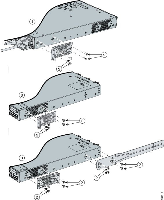
Attaching the Brackets
Use four number-8 Phillips flat-head screws to attach the long side of each bracket to the switch in one of these mounting positions.
Figure 2 Attaching the brackets to the switch
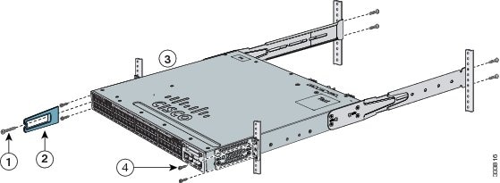
Rack-Mount the Switch
Use the four number-12 Phillips machine screws to attach the brackets to the rack. Use the black Phillips machine screw to attach the cable guide to the left or right bracket.
Warning![]() To prevent bodily injury when mounting or servicing this unit in a rack, you must take special precautions to ensure that the system remains stable. The following guidelines are provided to ensure your safety:
To prevent bodily injury when mounting or servicing this unit in a rack, you must take special precautions to ensure that the system remains stable. The following guidelines are provided to ensure your safety:
This unit should be mounted at the bottom of the rack if it is the only unit in the rack.
When mounting this unit in a partially filled rack, load the rack from the bottom to the top with the heaviest component at the bottom of the rack.
If the rack is provided with stabilizing devices, install the stabilizers before mounting or servicing the unit in the rack. Statement 1006
Figure 3 Attaching the brackets to the rack
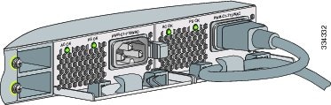
Securing the AC Power Cord (Optional)
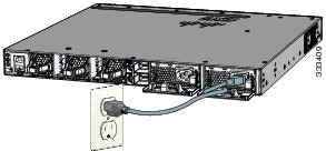
Make a loop in the power cord and thread it through the power cord retainer. Connect the power cord to the power supply.
Figure 4 Securing the AC power cord
Connecting the StackWise Cables
You can stack the Catalyst 3850 switch with other Catalyst 3850 switches. Before connecting the StackWise cables, review the “Planning a Switch Data Stack” section in the Catalyst 3850 Switch Hardware Installation Guide.
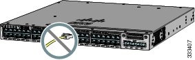
Always use a Cisco-approved StackWise cable to connect the switches.
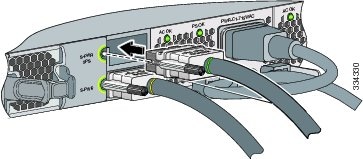
To connect the cable to the StackWise port on the switch rear panel:
Step 1![]() Make sure that the Cisco logo is oriented at the top-side of the connector as shown in the illustration.
Make sure that the Cisco logo is oriented at the top-side of the connector as shown in the illustration.
Step 2![]() Align the connector and connect the StackWise cable to the StackWise port on the switch rear panel and finger-tighten the screw (clockwise direction).
Align the connector and connect the StackWise cable to the StackWise port on the switch rear panel and finger-tighten the screw (clockwise direction).
Step 3![]() Connect the other end of the cable to the port on the other switch and finger-tighten the screw. Avoid overtightening the screws.
Connect the other end of the cable to the port on the other switch and finger-tighten the screw. Avoid overtightening the screws.
Figure 5 Inserting the StackWise cable into the StackWise port

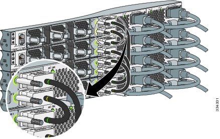
StackWise Cabling Configurations
This illustration shows a recommended stack configuration with connections using 0.5-meter StackWise cables.
Note![]() You cannot have a switch stack containing a mix of Catalyst 3850 and Catalyst 3650 switches.
You cannot have a switch stack containing a mix of Catalyst 3850 and Catalyst 3650 switches.
For more configuration examples, see the Catalyst 3850 Switch Hardware Installation Guide on Cisco.com at: http://www.cisco.com/go/cat3850_hw
Figure 6 Example of a StackWise cabling configuration

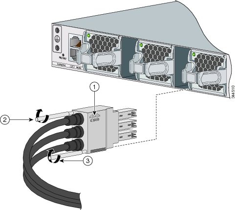
Connecting the StackPower Cables (Optional)
Always use a Cisco-approved StackPower cable to connect the switches.
Note![]() The Catalyst 3850 ports accept either the yellow or the green end of the StackPower cable.
The Catalyst 3850 ports accept either the yellow or the green end of the StackPower cable.
Align the connector and connect the StackPower cable to the S-PWR port on the switch rear panel and finger-tighten the screw. Connect the other end of the cable to the port on the other switch and finger-tighten the screw. Avoid overtightening the screws.
Figure 7 Connecting the StackPower cable to the S-PWR port
StackPower Cabling Configurations
You can configure a StackPower stack of up to four switches for either power-sharing or redundancy.
This illustration shows the recommended stack configuration with connections using 0.3-meter StackPower cables.
For more examples, see the Catalyst 3850 Switch Hardware Installation Guide on Cisco.com at:
http://www.cisco.com/go/cat3850_hw
Figure 8 Example of a StackPower stack configuration
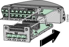
Installing the Network Module (Optional)
The switch accepts a hot-swappable network expansion module that provides SFP (1 Gigabit) and depending on the model, SFP+ (10 Gigabit) uplink ports.
Note![]() You need a number-2 Phillips screwdriver to install the network module.
You need a number-2 Phillips screwdriver to install the network module.

Connecting the Switch Ports
10/100/1000, 10/100/1000 PoE+, or 10/100/1000 Cisco UPOE Ports
When you connect to servers, workstations, IP phones, wireless access points, and routers:
- Use a straight-through, twisted four-pair, Category 5 cable in a 10/100/1000 port.
- Use a crossover, twisted four-pair, Category 5 cable when you connect to other switches, hubs, or repeaters.
- Connect the other cable end to an RJ-45 port on the other device.
In some switch models, the 10/100/1000 ports support Power over Ethernet (PoE), PoE+, or Cisco Universal Power Over Ethernet (Cisco UPOE).
- Support for IEEE 802.3af compliant powered devices (up to 15.4 W) PoE
- Support for IEEE 802.3at compliant powered devices (up to 30 W) PoE+
For more details, see the Catalyst 3850 Switch Hardware Installation Guide on Cisco.com.
Note![]() The automatic medium-dependent interface crossover (auto-MDIX) feature is enabled by default. The switch detects the required cable type for copper Ethernet connections and configures the interfaces. You can use either a crossover or a straight-through cable for connections to a copper 10/100/1000 module port on the switch, regardless of the type of connected device.
The automatic medium-dependent interface crossover (auto-MDIX) feature is enabled by default. The switch detects the required cable type for copper Ethernet connections and configures the interfaces. You can use either a crossover or a straight-through cable for connections to a copper 10/100/1000 module port on the switch, regardless of the type of connected device.
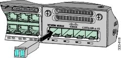
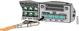
SFP and SFP+ Tranceiver Module Ports
Use only Cisco SFP transceiver modules with the switch. For a list of supported modules, see the Catalyst 3850 Switch Hardware Installation Guide. For detailed instructions on installing, removing, and connecting to SFP transceiver modules, see the SFP and SFP+ transceiver modules documentation.
Verify Port Connectivity
After you connect a device to the switch port, the port LED turns amber for about 30 seconds while the switch establishes a link. The LED turns green when the switch and the attached device have a link. If the LED is off, the device might not be turned on, there might be a cable problem, or there might be a problem with the adapter installed in the device.
Troubleshooting
This section includes Express Setup troubleshooting, how to reset the switch, how to access help online, and where to find more information.
Express Setup
If Express Setup does not run, or if the Express Setup page does not appear in your browser:
Resetting the Switch
To reset the switch to the factory defaults:
Step 1![]() If you are using Cisco IOS XE Release 3.6.0E or later releases, enter the erase startup-config privileged EXEC command to clear the contents of your startup configuration.If you are using an earlier release, you can skip this step.
If you are using Cisco IOS XE Release 3.6.0E or later releases, enter the erase startup-config privileged EXEC command to clear the contents of your startup configuration.If you are using an earlier release, you can skip this step.
Step 2![]() Press and hold the Mode button. The switch LEDs begin blinking after about 3 seconds.
Press and hold the Mode button. The switch LEDs begin blinking after about 3 seconds.
Step 3![]() Continue holding down the Mode button. The LEDs stop blinking after 7 more seconds, and then the switch restarts.
Continue holding down the Mode button. The LEDs stop blinking after 7 more seconds, and then the switch restarts.
Step 4![]() The switch now operates like an unconfigured switch. You can enter the switch IP information by using Express Setup as described in the “Running Express Setup” section.
The switch now operates like an unconfigured switch. You can enter the switch IP information by using Express Setup as described in the “Running Express Setup” section.
Accessing Help Online
Look for a solution to your problem in the troubleshooting section of the Catalyst 3850 Switch Hardware Installation Guide or the Catalyst 3850 Switch Software Configuration Guide on Cisco.com. You can also access the Cisco Technical Support and Documentation website for a list of known hardware problems and extensive troubleshooting documentation.
Obtaining Documentation and Submitting a Service Request
For information on obtaining documentation, submitting a service request, and gathering additional information, see the monthly What’s New in Cisco Product Documentation, which also lists all new and revised Cisco technical documentation, at:
http://www.cisco.com/en/US/docs/general/whatsnew/whatsnew.html
Subscribe to the What’s New in Cisco Product Documentation as a Really Simple Syndication (RSS) feed and set content to be delivered directly to your desktop using a reader application. The RSS feeds are a free service and Cisco currently supports RSS Version 2.0.
Related Documentation
Note![]() Before installing or upgrading the switch, refer to the switch release notes.
Before installing or upgrading the switch, refer to the switch release notes.
http://www.cisco.com/go/cat3850_docs
http://www.cisco.com/en/US/products/hw/modules/ps5455/tsd_products_support_series_home.html
http://www.cisco.com/go/designzone
https://www.cisco.com/cgi-bin/Support/Errordecoder/index.cgi
Cisco and the Cisco logo are trademarks or registered trademarks of Cisco and/or its affiliates in the U.S. and other countries. To view a list of Cisco trademarks, go to this URL: www.cisco.com/go/trademarks. Third-party trademarks mentioned are the property of their respective owners. The use of the word partner does not imply a partnership relationship between Cisco and any other company. (1721R)
Any Internet Protocol (IP) addresses used in this document are not intended to be actual addresses. Any examples, command display output, and figures included in the document are shown for illustrative purposes only. Any use of actual IP addresses in illustrative content is unintentional and coincidental.
 Feedback
Contact Cisco
- Open a Support Case

- (Requires a Cisco Service Contract)