Connector Specifications
- 10/100/1000 Ports
- 10 Gigabit Ethernet CX1 (SFP+ Copper) Connectors
- SFP and SFP+ Modules
- 10/100 Ethernet Management Port
- Console Port
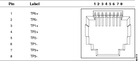
10/100/1000 Ports
The 10/100/1000 Ethernet ports on switches use RJ-45 connectors and Ethernet pinouts.
Figure B-1 10/100/1000 Port Pinouts
10 Gigabit Ethernet CX1 (SFP+ Copper) Connectors
The 10-Gigabit Ethernet electrical modules use CX1 copper connectors similar to the one shown in Figure B-2.

Note![]() When ordering or using CX1 cables, ensure that the version identifier is 2 or higher.
When ordering or using CX1 cables, ensure that the version identifier is 2 or higher.
The 10-Gigabit Ethernet optical modules use the connectors shown in Figure B-3 and Figure B-4.
Figure B-2 10-Gigabit Ethernet CX1 Copper Connector (example)
SFP and SFP+ Modules
Figure B-3, Figure B-4, and Figure B-5 show the SFP module connectors.
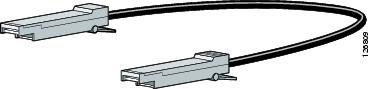
The Catalyst 3560-X switch supports the SFP module patch cable, a 0.5-meter, copper, passive cable with SFP module connectors at each end (Figure B-6). This cable can be used (only with 1-Gigabit Ethernet SFP ports) to connect two Catalyst 3560-X switches in a cascaded configuration.
Figure B-3 Duplex LC Cable Connector
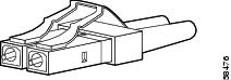
Figure B-4 Simplex LC Cable Connector
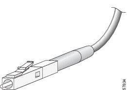
Figure B-5 Copper SFP Module RJ-45 Connector
Figure B-6 SFP Module Patch Cable (Catalyst 3560-X Switches)
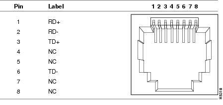
10/100 Ethernet Management Port
The 10/100 Ethernet management port uses RJ-45 connectors with Ethernet pinouts. Figure B-7 shows the pinouts.
Figure B-7 10/100 Port Pinouts
Console Port
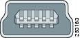
The switch has two console ports: a USB 5-pin mini-Type B port on the front panel (see Figure B-8) and an RJ-45 console port on the rear panel.
Figure B-8 USB Mini-Type B Port
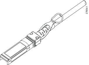
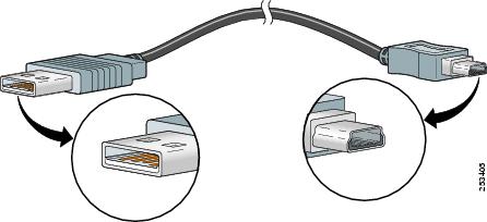
The USB console port uses a USB Type A to 5-pin mini-Type B cable, shown in Figure B-9. The USB Type A-to-USB mini-Type B cable is not supplied. You can order an accessory kit (part number 800-33434) that contains this cable.
Figure B-9 USB Type A-to-USB 5-Pin Mini-Type B Cable
The RJ-45 console port uses an 8-pin RJ-45 connector (See Table B-2 and Table B-3 .) The supplied RJ-45-to-DB-9 adapter cable is used to connect the console port of the switch to a console PC. You need to provide a RJ-45-to-DB-25 female DTE adapter if you want to connect the switch console port to a terminal. You can order a kit (part number ACS-DSBUASYN=) containing that adapter. For console port and adapter pinout information, see Table B-2 and Table B-3 .
Cable and Adapter Specifications
- SFP and SFP+ Module Cable Specifications
- Four Twisted-Pair Cable Pinouts
- Two Twisted-Pair Cable Pinouts
- Identifying a Crossover Cable
- Console Port Adapter Pinouts
SFP and SFP+ Module Cable Specifications
Each port must match the wave-length specifications on each end of the cable, and the cable must not exceed the stipulated cable length. Copper 1000BASE-T SFP module transceivers use standard four twisted-pair, Category 5 cable at lengths up to 328 feet (100 meters).
|
|
|
|
|
|
|
|---|---|---|---|---|---|
G.6522 |
|||||
722 feet (220 m) |
|||||
MMF3 |
1,804 feet (550 m) |
||||
43.4 to 62 miles |
|||||
1560.61, 1561.42, 1559.79, 1558.98, 1558.17, 1557.36, 1556.55, 1555.75, 1554.94, 1554.13, 1552.52, 1553.33, 1551.72, 1550.92, 1550.12, 1549.32, 1548.51, 1547.72, 1546.92, 1546.12, 1545.32, 1544.53, 1543.73, 1542.94, 1542.14, 1541.35, 1540.56, 1539.77, 1538.98, 1538.19, 1537.40, 1536.61, 1535.82, 1535.04, 1534.25, 1533.47, 1532.68, 1531.90, 1531.12, 1530.33 |
|||||
85 feet (26 m) |
|||||
|
Four Twisted-Pair Cable Pinouts
Figure B-10 Four Twisted-Pair Straight-Through Cable Schematic
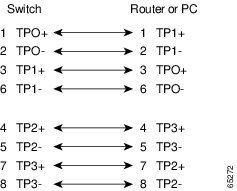
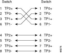
Figure B-11 Four Twisted-Pair Crossover Cable Schematic
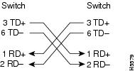
Two Twisted-Pair Cable Pinouts
Figure B-12 Two Twisted-Pair Straight-Through Cable Schematic
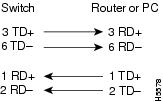
Figure B-13 Two Twisted-Pair Crossover Cable Schematic
Identifying a Crossover Cable
TYou can identify a crossover cable by comparing the two modular ends of the cable. Hold the cables side-by-side with the tab at the back. The first (far left) colored wire (pin 1) at one end of the cable is the third colored wire (pin 3) at the other end of the cable. The second colored wire (pin 2) at one end of the cable is the sixth colored wire (pin 6) at the other end of the cable. See Figure B-14.
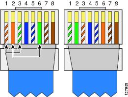
Figure B-15 RJ-45 Crossover Cable Identification
Console Port Adapter Pinouts
The console port uses an 8-pin RJ-45 connector, which is described in Table B-2 and Table B-3 . If you did not order a console cable, you need to provide an RJ-45-to-DB-9 adapter cable to connect the switch console port to a PC console port. You need to provide an RF-45-to-DB-25 female DTE adapter if you want to connect the switch console port to a terminal. You can order a kit with an adapter (part number ACS-DSBUASYN=). For console port and adapter pinout information, see Table B-2 and Table B-3 .
Table B-2 lists the pinouts for the console port, the RF-45-to-DB-9 adapter cable, and the console device.
|
Port (DTE) |
Terminal Adapter |
Device |
|---|---|---|
|
|
|
|
Table B-3 lists the pinouts for the console port, RJ-45-to-DB-25 female DTE adapter, and the console device.
Note![]() The RJ-45-to-DB-25 female DTE adapter is not supplied with the switch. You can order a kit with the adapter (part number ACS-DSBUASYN=) from Cisco.
The RJ-45-to-DB-25 female DTE adapter is not supplied with the switch. You can order a kit with the adapter (part number ACS-DSBUASYN=) from Cisco.
|
Port (DTE) |
Terminal A dapter |
Device |
|---|---|---|
|
|
|
|
Connector Specifications
- 10/100/1000 Ports
- 10 Gigabit Ethernet CX1 (SFP+ Copper) Connectors
- SFP and SFP+ Modules
- 10/100 Ethernet Management Port
- Console Port
10/100/1000 Ports
The 10/100/1000 Ethernet ports on switches use RJ-45 connectors and Ethernet pinouts.
Figure B-1 10/100/1000 Port Pinouts
10 Gigabit Ethernet CX1 (SFP+ Copper) Connectors
The 10-Gigabit Ethernet electrical modules use CX1 copper connectors similar to the one shown in Figure B-2.
Note
When ordering or using CX1 cables, ensure that the version identifier is 2 or higher.
The 10-Gigabit Ethernet optical modules use the connectors shown in Figure B-3 and Figure B-4.
Figure B-2 10-Gigabit Ethernet CX1 Copper Connector (example)
SFP and SFP+ Modules
Figure B-3, Figure B-4, and Figure B-5 show the SFP module connectors.
The Catalyst 3560-X switch supports the SFP module patch cable, a 0.5-meter, copper, passive cable with SFP module connectors at each end (Figure B-6). This cable can be used (only with 1-Gigabit Ethernet SFP ports) to connect two Catalyst 3560-X switches in a cascaded configuration.
Figure B-3 Duplex LC Cable Connector
Figure B-4 Simplex LC Cable Connector
Figure B-5 Copper SFP Module RJ-45 Connector
Figure B-6 SFP Module Patch Cable (Catalyst 3560-X Switches)
10/100 Ethernet Management Port
The 10/100 Ethernet management port uses RJ-45 connectors with Ethernet pinouts. Figure B-7 shows the pinouts.
Figure B-7 10/100 Port Pinouts
Console Port
The switch has two console ports: a USB 5-pin mini-Type B port on the front panel (see Figure B-8) and an RJ-45 console port on the rear panel.
Figure B-8 USB Mini-Type B Port
The USB console port uses a USB Type A to 5-pin mini-Type B cable, shown in Figure B-9. The USB Type A-to-USB mini-Type B cable is not supplied. You can order an accessory kit (part number 800-33434) that contains this cable.
Figure B-9 USB Type A-to-USB 5-Pin Mini-Type B Cable
The RJ-45 console port uses an 8-pin RJ-45 connector (See Table B-2 and Table B-3 .) The supplied RJ-45-to-DB-9 adapter cable is used to connect the console port of the switch to a console PC. You need to provide a RJ-45-to-DB-25 female DTE adapter if you want to connect the switch console port to a terminal. You can order a kit (part number ACS-DSBUASYN=) containing that adapter. For console port and adapter pinout information, see Table B-2 and Table B-3 .
Cable and Adapter Specifications
- SFP and SFP+ Module Cable Specifications
- Four Twisted-Pair Cable Pinouts
- Two Twisted-Pair Cable Pinouts
- Identifying a Crossover Cable
- Console Port Adapter Pinouts
SFP and SFP+ Module Cable Specifications
Each port must match the wave-length specifications on each end of the cable, and the cable must not exceed the stipulated cable length. Copper 1000BASE-T SFP module transceivers use standard four twisted-pair, Category 5 cable at lengths up to 328 feet (100 meters).
Table B-1 Fiber-Optic SFP and SFP+ Module Port Cabling Specifications
G.6522
722 feet (220 m)
902 feet (275 m)
1,640 feet (500 m)
1,804 feet (550 m)MMF3
SMF1,804 feet (550 m)
1,804 feet (550 m)
1,804 feet (550 m)
32,810 feet (10 km)43.4 to 62 miles
(70 to 100 km)41560.61, 1561.42, 1559.79, 1558.98, 1558.17, 1557.36, 1556.55, 1555.75, 1554.94, 1554.13, 1552.52, 1553.33, 1551.72, 1550.92, 1550.12, 1549.32, 1548.51, 1547.72, 1546.92, 1546.12, 1545.32, 1544.53, 1543.73, 1542.94, 1542.14, 1541.35, 1540.56, 1539.77, 1538.98, 1538.19, 1537.40, 1536.61, 1535.82, 1535.04, 1534.25, 1533.47, 1532.68, 1531.90, 1531.12, 1530.33
85 feet (26 m)
108 feet (33 m)
216 feet (66 m)
269 feet (82 m)
6,561 feet (2000 m)
Twinax cable, 30-AWG cable assemblyFour Twisted-Pair Cable Pinouts
Figure B-10 Four Twisted-Pair Straight-Through Cable Schematic
Figure B-11 Four Twisted-Pair Crossover Cable Schematic
Two Twisted-Pair Cable Pinouts
Figure B-12 Two Twisted-Pair Straight-Through Cable Schematic
Figure B-13 Two Twisted-Pair Crossover Cable Schematic
Identifying a Crossover Cable
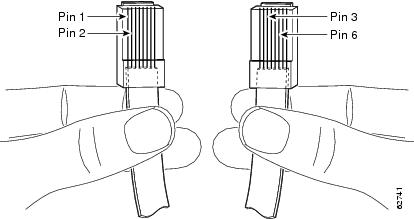
TYou can identify a crossover cable by comparing the two modular ends of the cable. Hold the cables side-by-side with the tab at the back. The first (far left) colored wire (pin 1) at one end of the cable is the third colored wire (pin 3) at the other end of the cable. The second colored wire (pin 2) at one end of the cable is the sixth colored wire (pin 6) at the other end of the cable. See Figure B-14.
Figure B-15 RJ-45 Crossover Cable Identification
Console Port Adapter Pinouts
The console port uses an 8-pin RJ-45 connector, which is described in Table B-2 and Table B-3 . If you did not order a console cable, you need to provide an RJ-45-to-DB-9 adapter cable to connect the switch console port to a PC console port. You need to provide an RF-45-to-DB-25 female DTE adapter if you want to connect the switch console port to a terminal. You can order a kit with an adapter (part number ACS-DSBUASYN=). For console port and adapter pinout information, see Table B-2 and Table B-3 .
Table B-2 lists the pinouts for the console port, the RF-45-to-DB-9 adapter cable, and the console device.
Table B-3 lists the pinouts for the console port, RJ-45-to-DB-25 female DTE adapter, and the console device.
Note
 Feedback