- Preparing for Installation
- Verifying Switch Operation
- Planning the Stack
- Installing the Switch
Switch Installation
This chapter describes how to start your switch and how to interpret the power-on self-test (POST) that ensures proper operation. It describes the planning and cabling considerations to keep in mind while planning your stack. It describes how to install the switch and make connections to the switch. Read the topics and perform the procedures in this order:
•![]() Connecting StackWise Cable to StackWise Ports
Connecting StackWise Cable to StackWise Ports
•![]() Installing and Removing SFP Modules
Installing and Removing SFP Modules
•![]() Installing and Removing XENPAK Modules (Catalyst 3750G-16TD Switch)
Installing and Removing XENPAK Modules (Catalyst 3750G-16TD Switch)
•![]() Connecting to the 10/100 and 10/100/1000 Ports
Connecting to the 10/100 and 10/100/1000 Ports
•![]() Connecting to a XENPAK Module
Connecting to a XENPAK Module
Preparing for Installation
This section covers these topics:
Warnings
These warnings are translated into several languages in the Regulatory Compliance and Safety Information for the Catalyst 3750 Switch guide.
 |
Warning |
|
Warning |
|
Warning |
|
Warning PWR-RPS2300, PWR675-AC-RPS-N1=. Statement 370 |
|
Warning |
|
Warning |
|
Warning |
|
Warning |

Note ![]() This warning applies only to the Catalyst 3750G-12S-SD switch.
This warning applies only to the Catalyst 3750G-12S-SD switch.
|
Warning |
Note ![]() This warning applies to all the Catalyst 3750 switches except the Catalyst 3750G-12S-SD switch.
This warning applies to all the Catalyst 3750 switches except the Catalyst 3750G-12S-SD switch.
|
Warning |
|
Warning |
|
Warning |
|
Warning Statement 1022 |
|
Warning |
|
Warning |
|
Warning |
|
Warning |
|
Warning |
|
Warning |
|
Warning |
|
Warning |
|
Warning |
|
Warning |
|
Warning |
Statement 371—Power Cable and AC Adapter


Note ![]() The grounding architecture of this product is DC-isolated (DC-I).
The grounding architecture of this product is DC-isolated (DC-I).
Catalyst 3750G Integrated Wireless LAN Controller Switches
This warning applies only to the Catalyst 3750G-24WS-S25 and 3750G-24WS-S50 switches:
|
Warning |
Installation Guidelines
When you decide where to place the switch, be sure to observe these requirements:
•![]() For copper Ethernet ports, including 10/100 ports, 10/100/1000 ports, and 1000BASE-T SFP module ports, cable lengths from the switch to connected devices can be up to 328 feet (100 meters).
For copper Ethernet ports, including 10/100 ports, 10/100/1000 ports, and 1000BASE-T SFP module ports, cable lengths from the switch to connected devices can be up to 328 feet (100 meters).
•![]() See Table B-3 for a list of cable specifications for 1000BASE-SX, 1000BASE-LX, 1000BASE-ZX, and CWDM fiber-optic SFP module connections. Each port must match the wave-length specifications on the other end of the cable, and for reliable communications, the cable must not exceed the stipulated cable length.
See Table B-3 for a list of cable specifications for 1000BASE-SX, 1000BASE-LX, 1000BASE-ZX, and CWDM fiber-optic SFP module connections. Each port must match the wave-length specifications on the other end of the cable, and for reliable communications, the cable must not exceed the stipulated cable length.
•![]() See the Catalyst 3750 release notes for cable requirements for XENPAK module connections. Each port must match the wave-length specifications on the other end of the cable, and for reliable communications, the cable must not exceed the required cable length.
See the Catalyst 3750 release notes for cable requirements for XENPAK module connections. Each port must match the wave-length specifications on the other end of the cable, and for reliable communications, the cable must not exceed the required cable length.
Note ![]() When you use shorter distances of single-mode fiber cable, you might need to insert an inline optical attenuator in the link to avoid overloading the receiver.
When you use shorter distances of single-mode fiber cable, you might need to insert an inline optical attenuator in the link to avoid overloading the receiver.
When the fiber-optic cable span is less than 25 km, you should insert a 5-decibel (dB) or 10-dB inline optical attenuator between the fiber-optic cable plant and the receiving port on the 1000BASE-ZX SFP module at each end of the link.
•![]() The operating environment must be within the ranges listed in "Technical Specifications."
The operating environment must be within the ranges listed in "Technical Specifications."
•![]() Clearance to front and rear panels must be such that
Clearance to front and rear panels must be such that
–![]() You can easily read the front-panel indicators.
You can easily read the front-panel indicators.
–![]() Access to ports is sufficient for unrestricted cabling.
Access to ports is sufficient for unrestricted cabling.
Make sure that there is access to the rear of the rack if you are planning to stack the switches. If you do not have access to the rear panel, make sure that you cable the switches before you rack-mount them.
–![]() The AC power cord can reach from the AC power outlet to the connector on the switch rear panel.
The AC power cord can reach from the AC power outlet to the connector on the switch rear panel.
•![]() Cabling must be away from sources of electrical noise, such as radios, power lines, and fluorescent lighting fixtures. Make sure the cabling is safely away from other devices that might damage the cables.
Cabling must be away from sources of electrical noise, such as radios, power lines, and fluorescent lighting fixtures. Make sure the cabling is safely away from other devices that might damage the cables.
•![]() Airflow around the switch and through the vents must be unrestricted.
Airflow around the switch and through the vents must be unrestricted.
•![]() Temperature around the unit should not exceed 113°F (45°C).
Temperature around the unit should not exceed 113°F (45°C).
Note ![]() If you install the switch in a closed or multirack assembly, the temperature around it might be greater than normal room temperature.
If you install the switch in a closed or multirack assembly, the temperature around it might be greater than normal room temperature.
•![]() Cisco Ethernet Switches are equipped with cooling mechanisms, such as fans and blowers. However, these fans and blowers can draw dust and other particles, causing contaminant buildup inside the chassis, which can result in a system malfunction.
Cisco Ethernet Switches are equipped with cooling mechanisms, such as fans and blowers. However, these fans and blowers can draw dust and other particles, causing contaminant buildup inside the chassis, which can result in a system malfunction.
You must install this equipment in an environment as free as possible from dust and foreign conductive material (such as metal flakes from construction activities).
These standards provide guidelines for acceptable working environments and acceptable levels of suspended particulate matter:
–![]() Network Equipment Building Systems (NEBS) GR-63-CORE
Network Equipment Building Systems (NEBS) GR-63-CORE
–![]() National Electrical Manufacturers Association (NEMA) Type 1
National Electrical Manufacturers Association (NEMA) Type 1
–![]() International Electrotechnical Commission (IEC) IP-20
International Electrotechnical Commission (IEC) IP-20
Box Contents
The switch getting started guide on Cisco.com describes the box contents. If any item is missing or damaged, contact your Cisco representative or reseller for support.
Tools and Equipment
You need to supply a number-2 Phillips screwdriver to rack-mount the switch.
Verifying Switch Operation
Before you install the switch in a rack, on a wall, or on a table or shelf, you should power on the switch and verify that the switch passes POST. See the "Running Express Setup" section in the getting started guide for the steps required to connect a PC to the switch and to run Express Setup.
Powering On the Switch and Running POST
If your configuration has an RPS, connect the switch and the RPS to the same AC power source. See the "Power Connectors" section, and see the Cisco RPS documentation for more information.
Note ![]() Always set the RPS in standby mode when you are connecting devices to it and in active mode during normal operation.
Always set the RPS in standby mode when you are connecting devices to it and in active mode during normal operation.
To power on the switch, connect one end of the AC power cord to the AC power connector on the switch, and connect the other end of the power cord to an AC power outlet.
To power on a DC switch, see "Connecting to DC Power," for complete instructions.
|
Warning PWR-RPS2300, PWR675-AC-RPS-N1=. Statement 370 |
As the switch powers on, it begins the POST, a series of tests that runs automatically to ensure that the switch functions properly. POST lasts approximately 1 minute.
When the switch begins POST, the System, the RPS, the Master, the Status, the Duplex, the Speed, and the Stack LEDs turn green. (On the PoE switches, the PoE LED also turns green as POST begins.) The System LED flashes green, and the other LEDs remain continuous green.
When POST completes successfully, the System LED remains green. The RPS LED remains green for some time and then returns to its operating status. The other LEDs turn off and return to their operating status. When POST fails, the System LED turns amber.
Note ![]() POST failures are usually fatal. Call Cisco Systems if your switch does not pass POST.
POST failures are usually fatal. Call Cisco Systems if your switch does not pass POST.
Powering Off the Switch
After a successful POST, disconnect the power cord from the switch. Install the switch in a rack, on a wall, on a table, or on a shelf as described in the "Installing the Switch" section.
Planning the Stack
If you plan to stack your switches, read these sections:
•![]() Recommended Cabling Configurations
Recommended Cabling Configurations
Planning Considerations
Before connecting the Catalyst 3750 switches in a stack, observe these planning considerations:
•![]() Size of the switch. For switch dimensions, see "Technical Specifications." Some switches are deeper than the other switches. Stacking switches of the same size together makes it easier to cable the switches.
Size of the switch. For switch dimensions, see "Technical Specifications." Some switches are deeper than the other switches. Stacking switches of the same size together makes it easier to cable the switches.
•![]() Length of cable. Depending on the configurations that you have, you might need cables of different sizes. If you do not specify the length of the StackWise cable, the 0.5-meter cable is supplied. If you require the 1-meter cable or the 3-meter cable, you can order it from your Cisco supplier. For cable numbers, see the "StackWise Ports" section. The "Recommended Cabling Configurations" section provides examples of recommended configurations.
Length of cable. Depending on the configurations that you have, you might need cables of different sizes. If you do not specify the length of the StackWise cable, the 0.5-meter cable is supplied. If you require the 1-meter cable or the 3-meter cable, you can order it from your Cisco supplier. For cable numbers, see the "StackWise Ports" section. The "Recommended Cabling Configurations" section provides examples of recommended configurations.
•![]() Access to the rear ports for unrestricted cabling.
Access to the rear ports for unrestricted cabling.
Make sure that you have access to the rear of the rack if you plan to stack the switches. If you do not have access to the rear panel, make sure that you cable the switches before you rack-mount them.
•![]() For concepts and procedures to manage switch stacks, see the switch software configuration guide.
For concepts and procedures to manage switch stacks, see the switch software configuration guide.
Powering Considerations
Consider the following guidelines before you power on the switches in a stack:
•![]() The sequence in which you initially power on the switches might affect the switch that becomes the stack master.
The sequence in which you initially power on the switches might affect the switch that becomes the stack master.
•![]() If you want a particular switch to become the stack master, power on that switch first. This switch becomes the stack master and remains the stack master until a master re-election is required. After approximately 10 seconds, power on the remaining switches in the stack.
If you want a particular switch to become the stack master, power on that switch first. This switch becomes the stack master and remains the stack master until a master re-election is required. After approximately 10 seconds, power on the remaining switches in the stack.
•![]() If you have no preference as to which switch becomes the stack master, power on all the switches in the stack within a 10-second timeframe. These switches participate in the stack master election. Switches powered up after the 10-second timeframe do not participate in the election.
If you have no preference as to which switch becomes the stack master, power on all the switches in the stack within a 10-second timeframe. These switches participate in the stack master election. Switches powered up after the 10-second timeframe do not participate in the election.
•![]() Power off a switch before you add it to or remove it from an existing switch stack.
Power off a switch before you add it to or remove it from an existing switch stack.
Note ![]() For conditions that can cause a stack master re-election or to manually elect the stack master, see the "Managing Switch Stacks" chapter in the switch software configuration guide.
For conditions that can cause a stack master re-election or to manually elect the stack master, see the "Managing Switch Stacks" chapter in the switch software configuration guide.
Cabling Considerations
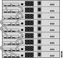
The illustrations in this section display cabling configuration examples that show the stack bandwidth and possible stack partitioning.
Figure 2-1 shows an example of a stack of Catalyst 3750 switches that provides full bandwidth and redundant StackWise cable connections.
Figure 2-1 Example of a Stack with Full Bandwidth Connections
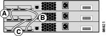
Figure 2-2 shows an example of a stack of Catalyst 3750 switches with incomplete StackWise cabling connections. This stack provides only half bandwidth and does not have redundant connections.
Figure 2-2 Example of a Stack with Half Bandwidth Connections
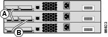
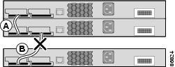
Figure 2-3 and Figure 2-4 show examples of stacks of Catalyst 3750 switches with failover conditions. In Figure 2-3, the StackWise cable is bad in link B; therefore, this stack provides only half bandwidth and does not have redundant connections. In Figure 2-4, link B is bad; therefore, this stack partitions into two stacks, and switch 1 and switch 3 are stack masters.
Figure 2-3 Example of a Stack with a Failover Condition
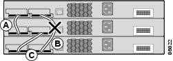
Figure 2-4 Example of a Partitioned Stack with a Failover Condition
Recommended Cabling Configurations
This section describes the recommended cabling configurations for stacking the switches.
Stacking Switches in Vertical Racks or on a Table
Figure 2-5 is an example of a recommended configuration using the supplied 0.5-meter StackWise cable. In this example, the switches are stacked in a vertical rack or on a table. This configuration provides redundant connections.
Figure 2-5 Stacking the Switches in a Vertical Rack or on a Table Using the 0.5-meter StackWise Cable
The configuration examples in Figure 2-6 use the 3-meter StackWise cable in addition to the supplied 0.5-meter StackWise cable. This configuration also provides redundant connections.
Figure 2-6 Stacking the Catalyst 3750 Switches in a Vertical Rack or on a Table Using 0.5-meter and 3-meter StackWise Cables
Side-by-Side Mounting in a Rack or on a Wall
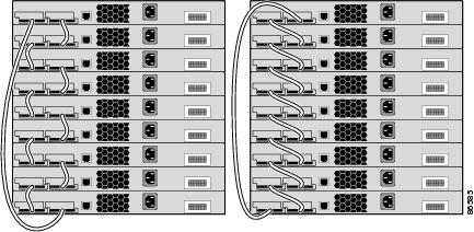
Figure 2-7 and Figure 2-8 are examples of recommended configurations where the switches are rack- or wall-mounted side-by-side. Use the 1-meter and 3-meter StackWise cables to connect the switches. These configuration provide redundant connections.
Figure 2-7 Stacking up to Eight Switches in a Side-by-Side Mounting Configuration

Figure 2-8 Stacking Nine Switches in a Side-by-Side Mounting Configuration 90532

Installing the Switch
This section describes these installation procedures:
Rack-Mounting
|
To prevent bodily injury when mounting or servicing this unit in a rack, you must take special precautions to ensure that the system remains stable. The following guidelines are provided to ensure your safety: • • • |
To install the switch in a 19-inch or 24-inch rack (24-inch racks require optional mounting hardware), follow the instructions described in these procedures:
•![]() Removing Screws from the Switch
Removing Screws from the Switch
•![]() Attaching Brackets to the Catalyst 3750G-24TS Switch
Attaching Brackets to the Catalyst 3750G-24TS Switch
•![]() Attaching Brackets to the Catalyst 3750G Integrated Wireless LAN Controller Switches
Attaching Brackets to the Catalyst 3750G Integrated Wireless LAN Controller Switches
•![]() Attaching Brackets to All Other Catalyst 3750 Switches
Attaching Brackets to All Other Catalyst 3750 Switches
•![]() Mounting the Switch in a Rack
Mounting the Switch in a Rack
Note ![]() When you install the switch in a 24-inch rack, an optional bracket kit that is not included with the switch is required. You can order a kit containing the 24-inch rack-mounting brackets and hardware from Cisco. For the Catalyst 3750G-24TS switch, order part number RCKMNT-3550-1.5RU=. For the other Catalyst 3750 switches, order part number RCKMNT-1RU=. The Catalyst 3750G-24WS-S25 and the 3750G-24WS-S50 switch do not support 24-inch rack-mounting.
When you install the switch in a 24-inch rack, an optional bracket kit that is not included with the switch is required. You can order a kit containing the 24-inch rack-mounting brackets and hardware from Cisco. For the Catalyst 3750G-24TS switch, order part number RCKMNT-3550-1.5RU=. For the other Catalyst 3750 switches, order part number RCKMNT-1RU=. The Catalyst 3750G-24WS-S25 and the 3750G-24WS-S50 switch do not support 24-inch rack-mounting.
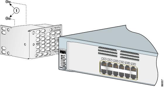
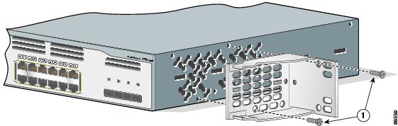
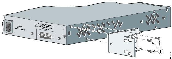
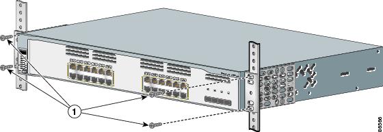
Removing Screws from the Switch
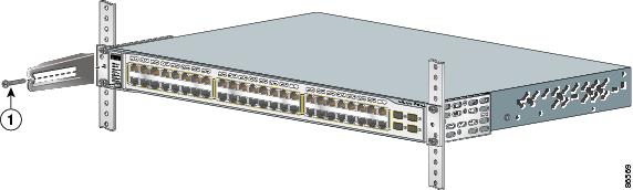
If you plan to install the switch in a rack, you must first remove the screws in the switch chassis so that you can attached the mounting brackets.
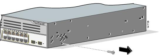
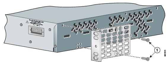
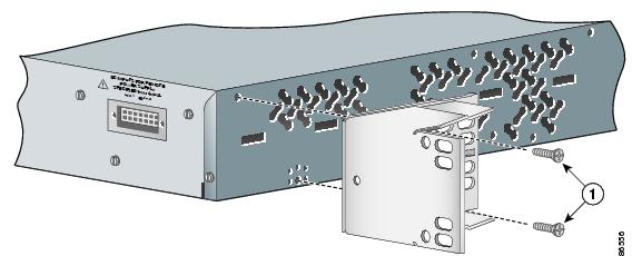
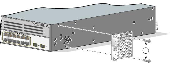
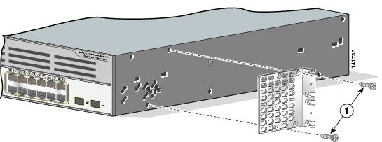
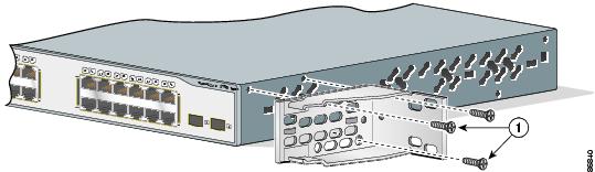
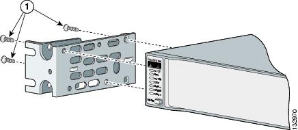
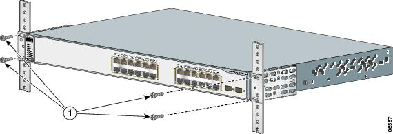
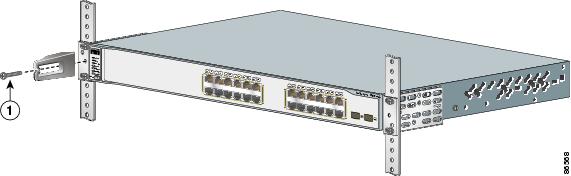
•![]() Figure 2-9, Figure 2-10, and Figure 2-11 show how to remove the chassis screws in a 1-rack-unit (RU) switch.
Figure 2-9, Figure 2-10, and Figure 2-11 show how to remove the chassis screws in a 1-rack-unit (RU) switch.
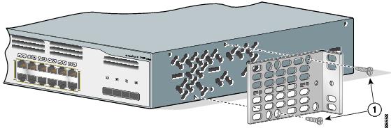
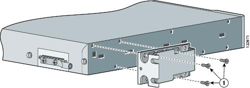
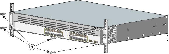
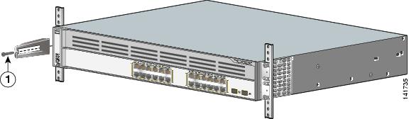
•![]() Figure 2-12 shows how to remove the chassis screws in a 1.5-RU switch.
Figure 2-12 shows how to remove the chassis screws in a 1.5-RU switch.
•![]() Figure 2-13 shows how to remove the chassis screws in a 2-RU switch.
Figure 2-13 shows how to remove the chassis screws in a 2-RU switch.
Figure 2-9 Removing Screws from the Catalyst 3750-24TS, 3750V2-24TS, 3750G-24T, 3750-24PS, 3750V2-24PS, 3750-48TS, 3750-48PS, 3750V2-48PS, and 3750G-16TD Switch
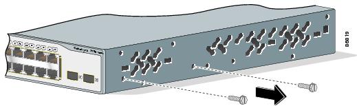
Figure 2-10 Removing Screws from the Catalyst 3750G-24TS-1U, 3750G-24PS, 3750G-48PS, and 3750G-48TS Switch
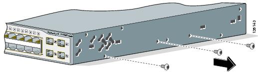
Figure 2-11 Removing Screws from the Catalyst 3750G-12S and 3750-12S-SD Switch
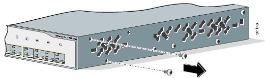
Figure 2-12 Removing Screws from the 3750G-24TS Switch
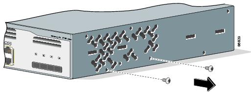
Figure 2-13 Removing Screws from the 3750G-24WS-S25 and the 3750G-24WS-S50 Switch
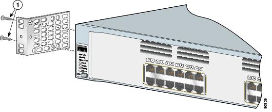
Attaching Brackets to the Catalyst 3750G-24TS Switch
The bracket orientation and the brackets that you use depend on whether you are attaching the brackets for a 19-inch or a 24-inch rack.
Figure 2-14 through Figure 2-19 show how to attach each type bracket to one side of the switch. Follow the same steps to attach the second bracket to the opposite side.
Figure 2-14 Attaching Brackets for 19-inch Racks, Front Panel Forward
|
|
Phillips flat-head screws |
Figure 2-15 Attaching Brackets for 24-Inch Racks, Front Panel Forward
|
|
Phillips flat-head screws |
Figure 2-16 Attaching Brackets for 19-Inch Racks, Rear Panel Forward
|
|
Phillips flat-head screws |
Figure 2-17 Attaching Brackets for 24-Inch Racks, Rear Panel Forward
|
|
Phillips flat-head screws |
Figure 2-18 Attaching Brackets for 19-Inch Telco Racks
|
|
Phillips flat-head screws |
Figure 2-19 Attaching Brackets for 24-Inch Telco Racks
|
|
Phillips flat-head screws |
Attaching Brackets to the Catalyst 3750G Integrated Wireless LAN Controller Switches
The wireless LAN controller switches can only be mounted on 19-inch racks. This section describes how to attach 19-inch brackets on the Catalyst 3750G-24WS-S25 and the 3750G-24WS-S50 switches. Figure 2-20, Figure 2-21, and Figure 2-22 show how to attach the bracket to one side of the switch. Follow the same steps to attach the second bracket to the opposite side. For 19-inch racks, use part number 700-21419-XX.
Figure 2-20 Attaching Brackets for 19-Inch Racks, Front Panel Forward
|
|
Phillips flat-head screws |
Figure 2-21 Attaching Brackets for 19-Inch Racks, Rear Panel Forward
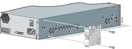
Figure 2-22 Attaching Brackets for 19-Inch Telco Racks
|
|
Phillips flat-head screws |
Attaching Brackets to All Other Catalyst 3750 Switches
This section describes how to attach brackets to these Catalyst 3750 switches:
•![]() Catalyst 3750-24TS, 3750V2-24TS, and 3750G-24TS
Catalyst 3750-24TS, 3750V2-24TS, and 3750G-24TS
•![]() Catalyst 3750G-24T
Catalyst 3750G-24T
•![]() Catalyst 3750-24FS and Catalyst 3750V2-24FS
Catalyst 3750-24FS and Catalyst 3750V2-24FS
•![]() Catalyst 3750G-12S and 3750G-12S-SD
Catalyst 3750G-12S and 3750G-12S-SD
•![]() Catalyst 3750-24PS, 3750V2-24PS, and 3750G-24PS
Catalyst 3750-24PS, 3750V2-24PS, and 3750G-24PS
•![]() Catalyst 3750-48PS, 3750V2-48PS, and 3750G-48PS
Catalyst 3750-48PS, 3750V2-48PS, and 3750G-48PS
•![]() Catalyst 3750G-16TD
Catalyst 3750G-16TD
•![]() Catalyst 3750-48TS, 3750V2-48TS, and 3750G-48TS
Catalyst 3750-48TS, 3750V2-48TS, and 3750G-48TS
The bracket orientation and the brackets that you use depend on whether you are attaching the brackets for a 19-inch, a 23-inch, a 24-inch rack, or a ETSI rack. Figure 2-23 shows the bracket options.
Figure 2-23 Rack-Mounting Brackets
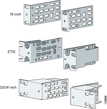
•![]() For 19-inch racks, use part number 700-08209-XX, and see Attaching Brackets for 19-Inch Racks and 19-Inch Telco Racks.
For 19-inch racks, use part number 700-08209-XX, and see Attaching Brackets for 19-Inch Racks and 19-Inch Telco Racks.
•![]() For 23-inch racks, use part number 700-21646-XX, and see Attaching Brackets for 23-Inch Racks.
For 23-inch racks, use part number 700-21646-XX, and see Attaching Brackets for 23-Inch Racks.
•![]() For 24-inch racks, use part number 700-12398-XX, and see Attaching Brackets for 24-Inch Racks and 24-Inch Telco Racks.
For 24-inch racks, use part number 700-12398-XX, and see Attaching Brackets for 24-Inch Racks and 24-Inch Telco Racks.
•![]() For ETSI racks, use part number 700-19781XX, and see Attaching Brackets for ETSI Racks.
For ETSI racks, use part number 700-19781XX, and see Attaching Brackets for ETSI Racks.
Attaching Brackets for 19-Inch Racks and 19-Inch Telco Racks
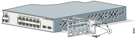
This section shows to attach brackets for 19-inch racks in Figure 2-24 through Figure 2-27. These illustrations show how to attach each type of bracket to one side of the switch. Follow the same steps to attach the second bracket to the opposite side.
Figure 2-24 Attaching Brackets for 19-Inch Racks, Front Panel Forward
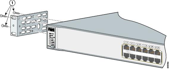
|
|
Phillips flat-head screws |
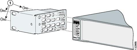
Figure 2-25 Attaching Brackets for 19-Inch Racks, Rear Panel Forward
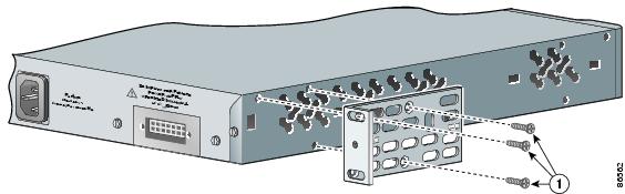
|
|
Phillips flat-head screws |
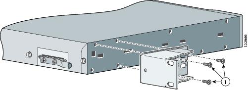
Figure 2-26 Attaching Brackets for 19-Inch Racks
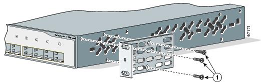
|
|
Phillips truss-head screws |
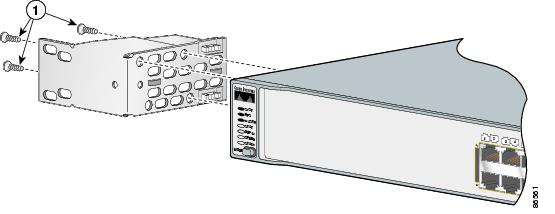
Figure 2-27 Attaching Brackets for 19-Inch Telco Racks
|
|
Phillips flat-head screws |
Attaching Brackets for 23-Inch Racks
This section shows to attach brackets for 23-inch racks in Figure 2-28 and Figure 2-29. These illustrations show how to attach each type of bracket to one side of the switch. Follow the same steps to attach the second bracket to the opposite side.
Figure 2-28 Attaching Brackets for 23-Inch Racks, Front Panel Forward
|
|
Phillips flat-head screws |
Figure 2-29 Attaching Brackets for 23-Inch Racks, Rear Panel Forward
|
|
Phillips flat-head screws |
Attaching Brackets for 24-Inch Racks and 24-Inch Telco Racks
This section shows to attach brackets for ESTI racks in Figure 2-30, Figure 2-31, and Figure 2-32. These illustrations show how to attach each type of bracket to one side of the switch. Follow the same steps to attach the second bracket to the opposite side.
Figure 2-30 Attaching Brackets for 24-Inch Racks, Front Panel Forward
|
|
Phillips flat-head screws |
Figure 2-31 Attaching Brackets for 24-Inch Racks, Rear Panel Forward
|
|
Phillips flat-head screws |
Figure 2-32 Attaching Brackets for 24-Inch Telco Racks
|
|
Phillips flat-head screws |
Attaching Brackets for ETSI Racks
This section shows to attach brackets for ESTI racks in Figure 2-33 and Figure 2-34. These illustrations show how to attach each type of bracket to one side of the switch. Follow the same steps to attach the second bracket to the opposite side.
Figure 2-33 Attaching Brackets for ESTI Racks, Front Panel Forward
|
|
Phillips flat-head screws |
Figure 2-34 Attaching Brackets for ETSI Racks, Rear Panel Forward
|
|
Phillips flat-head screws |
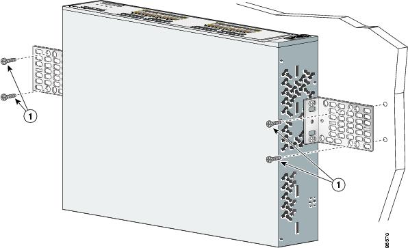
Mounting the Switch in a Rack
After the brackets are attached to the switch, use the four supplied number-12 Phillips machine screws to securely attach the brackets to the rack, as shown in Figure 2-35, Figure 2-36 and Figure 2-37.
Figure 2-35 Mounting the Catalyst 3750G-24TS Switch in a Rack
|
|
Phillips machine screws |
Figure 2-36 Mounting the Other Catalyst 3750 Switches in a Rack
|
|
Phillips machine screws |
Figure 2-37 Mounting the Catalyst 3750G-24WS-S25 and 3750G-24WS-S50 Switches in a Rack
|
|
Phillips machine screws |
After you mount the switch in the rack, you might need to perform these tasks to complete the installation, to run the setup program, and to access the switch:
•![]() (Optional) Connect the switches in the stacks. See the "Connecting StackWise Cable to StackWise Ports" section.
(Optional) Connect the switches in the stacks. See the "Connecting StackWise Cable to StackWise Ports" section.
•![]() Power on the switch. See the "Verifying Switch Operation" section. If the switches are stacked, see the "Planning Considerations" section for information on powering considerations.
Power on the switch. See the "Verifying Switch Operation" section. If the switches are stacked, see the "Planning Considerations" section for information on powering considerations.
•![]() Connect to a 10/100 or 10/100/1000 port and run Express Setup. See the Catalyst 3750 Switch Getting Started Guide for instructions.
Connect to a 10/100 or 10/100/1000 port and run Express Setup. See the Catalyst 3750 Switch Getting Started Guide for instructions.
•![]() Connect to the front-panel ports. See the "Connecting to the 10/100 and 10/100/1000 Ports" section and the "Connecting to an SFP Module" section to complete the installation.
Connect to the front-panel ports. See the "Connecting to the 10/100 and 10/100/1000 Ports" section and the "Connecting to an SFP Module" section to complete the installation.
For configuration instructions about using the CLI setup program, go to "Configuring the Switch with the CLI-Based Setup Program."
To use the CLI, enter commands at the Switch> prompt through the console port by using a terminal program or through the network by using Telnet. For configuration information, see the switch software configuration guide or the switch command reference.
Attaching the Cable Guide
We recommend attaching the cable guide to prevent the cables from obscuring the front panel of the switch and the other devices installed in the rack. Use the supplied black screw, as shown in Figure 2-38, Figure 2-39 and Figure 2-40 to attach the cable guide to the left or right bracket.
Figure 2-38 Attaching the Cable Guide on the 24-Port Catalyst 3750 Switches
|
|
Cable guide screws |
Note ![]() The 48-port Catalyst 3750 switches ship with the cable guide shown in Figure 2-39. This cable guide secures up to 48 cables. Use the supplied black screw to mount it on the left bracket.
The 48-port Catalyst 3750 switches ship with the cable guide shown in Figure 2-39. This cable guide secures up to 48 cables. Use the supplied black screw to mount it on the left bracket.
Figure 2-39 Attaching the Cable Guide on the 48-Port Catalyst 3750 Switches
|
|
Cable guide screws |
Figure 2-40 Attaching the Cable Guide on the Catalyst 3750 Integrated Wireless LAN Controller Switches
|
|
Cable guide screws |
Wall-Mounting
These switches wall-mount only with the front panel facing up:
•![]() Catalyst 3750-24FS, Catalyst 3750V2-24FS
Catalyst 3750-24FS, Catalyst 3750V2-24FS
•![]() Catalyst 3750-24TS, 3750-48TS, 3750-24PS, 3750-48PS
Catalyst 3750-24TS, 3750-48TS, 3750-24PS, 3750-48PS
•![]() Catalyst 3750G-12S, 3750G-12S-SD
Catalyst 3750G-12S, 3750G-12S-SD
•![]() Catalyst 3750G-24T, 3750G-24TS, 3750G-24TS-1U
Catalyst 3750G-24T, 3750G-24TS, 3750G-24TS-1U
•![]() Catalyst 3750G-24PS, 3750G-48PS
Catalyst 3750G-24PS, 3750G-48PS
•![]() Catalyst 3750G-16TD
Catalyst 3750G-16TD
These switches wall-mount with the front panel facing up or down:
•![]() Catalyst 3750V2-24TS, 3750V2-48TS
Catalyst 3750V2-24TS, 3750V2-48TS
•![]() Catalyst 3750V2-24PS, 3750V2-48PS
Catalyst 3750V2-24PS, 3750V2-48PS
These switches do not support wall-mounting. Do not wall-mount these switches:
•![]() Catalyst 3750G-24WS-S25
Catalyst 3750G-24WS-S25
•![]() Catalyst 3750G-24WS-S50
Catalyst 3750G-24WS-S50
The illustrations in this section show the Catalyst 3750G-24TS switch as an example.
|
Warning |
To install the switch on a wall, follow the instructions in these procedures:
•![]() Attaching the Brackets to the Switch for Wall-Mounting
Attaching the Brackets to the Switch for Wall-Mounting
•![]() Attaching the RPS Connector Cover
Attaching the RPS Connector Cover
•![]() Mounting the Switch on a Wall
Mounting the Switch on a Wall
Attaching the Brackets to the Switch for Wall-Mounting
Figure 2-41 shows how to attach a 19-inch bracket to one side of the switch. Follow the same steps to attach the second bracket to the opposite side.
Figure 2-41 Attaching the 19-inch Brackets for Wall-Mounting
|
|
Phillips truss-head screws |
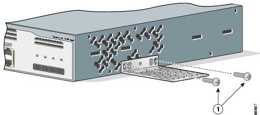
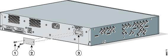
Attaching the RPS Connector Cover
If you are not using an RPS with your switch, use the two Phillips pan-head screws to attach the RPS connector cover to the back of the switch, as shown in Figure 2-42.
|
Warning |
Figure 2-42 Attaching the RPS Connector Cover on the Switch
|
|
Phillips pan-head screws |
|
RPS connector |
|
|
RPS connector cover |
Mounting the Switch on a Wall
For the best support of the switch and cables, make sure the switch is attached securely to wall studs or to a firmly attached plywood-mounting backboard. Mount the switch with the front panel facing up, as shown in Figure 2-43.
See the "Wall-Mounting" section for the switches that can also mount with the front panel facing down.
|
Warning |
Figure 2-43 Mounting the Switch on a Wall
|
|
User-supplied screws |
After the switch is mounted on the wall, you might need to perform these tasks to complete the installation, run the setup program, and access the switch:
•![]() (Optional) Connect the switches in the stacks. See the "Connecting StackWise Cable to StackWise Ports" section.
(Optional) Connect the switches in the stacks. See the "Connecting StackWise Cable to StackWise Ports" section.
•![]() Power on the switch. See the "Verifying Switch Operation" section. If the switches are stacked, see the "Planning Considerations" section for information on powering considerations.
Power on the switch. See the "Verifying Switch Operation" section. If the switches are stacked, see the "Planning Considerations" section for information on powering considerations.
•![]() Connect to a 10/100 or 10/100/1000 port and run Express Setup. See the Catalyst 3750 Switch Getting Started Guide for instructions.
Connect to a 10/100 or 10/100/1000 port and run Express Setup. See the Catalyst 3750 Switch Getting Started Guide for instructions.
•![]() Connect to the front-panel ports. See the "Connecting to the 10/100 and 10/100/1000 Ports" section and the "Connecting to an SFP Module" section to complete the installation.
Connect to the front-panel ports. See the "Connecting to the 10/100 and 10/100/1000 Ports" section and the "Connecting to an SFP Module" section to complete the installation.
For configuration instructions about using the CLI setup program, go to "Configuring the Switch with the CLI-Based Setup Program."
To use the CLI, enter commands at the Switch> prompt through the console port by using a terminal program or through the network by using Telnet. For configuration information, see the switch software configuration guide or the switch command reference.
Table- or Shelf-Mounting
Follow these steps to install the switch on a table or shelf:
Step 1 ![]() Locate the adhesive strip with the rubber feet in the mounting-kit envelope. Attach the four rubber feet to the recessed areas on the bottom of the unit.
Locate the adhesive strip with the rubber feet in the mounting-kit envelope. Attach the four rubber feet to the recessed areas on the bottom of the unit.
Step 2 ![]() Place the switch on the table or shelf near an AC power source.
Place the switch on the table or shelf near an AC power source.
After the switch is mounted on the table, you might need to perform these tasks to complete the installation, run the setup program, and access the switch:
•![]() (Optional) Connect the switches in the stacks. See the "Connecting StackWise Cable to StackWise Ports" section.
(Optional) Connect the switches in the stacks. See the "Connecting StackWise Cable to StackWise Ports" section.
•![]() Power on the switch. See the "Verifying Switch Operation" section. If the switches are stacked, see the "Planning Considerations" section for information on powering considerations.
Power on the switch. See the "Verifying Switch Operation" section. If the switches are stacked, see the "Planning Considerations" section for information on powering considerations.
•![]() Connect to a 10/100 or 10/100/1000 port and run Express Setup. See the Catalyst 3750 Switch Getting Started Guide for instructions.
Connect to a 10/100 or 10/100/1000 port and run Express Setup. See the Catalyst 3750 Switch Getting Started Guide for instructions.
•![]() Connect to the front-panel ports. See the "Connecting to the 10/100 and 10/100/1000 Ports" section and the "Connecting to an SFP Module" section to complete the installation.
Connect to the front-panel ports. See the "Connecting to the 10/100 and 10/100/1000 Ports" section and the "Connecting to an SFP Module" section to complete the installation.
For configuration instructions about using the CLI setup program, go to "Configuring the Switch with the CLI-Based Setup Program."
To use the CLI, enter commands at the Switch> prompt through the console port by using a terminal emulation program or through the network by using Telnet. For configuration information, see the switch software configuration guide or the switch command reference.
Connecting StackWise Cable to StackWise Ports
Follow these steps to connect the StackWise cable to the StackWise ports:
Step 1 ![]() Remove the dust covers from the StackWise cables and StackWise ports, and store them for future use.
Remove the dust covers from the StackWise cables and StackWise ports, and store them for future use.
Step 2 ![]() Insert one end of the StackWise cable into the StackWise port on the back of the switch. (See Figure 2-44.)
Insert one end of the StackWise cable into the StackWise port on the back of the switch. (See Figure 2-44.)
Note ![]() Always use a Cisco-approved StackWise cable to connect the switches.
Always use a Cisco-approved StackWise cable to connect the switches.
Figure 2-44 Inserting the StackWise Cable in a StackWise Port
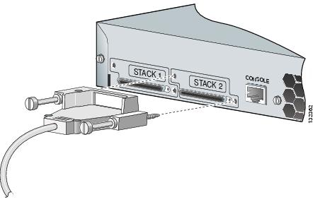
Step 3 ![]() Use the window in the StackWise cable to align the connector correctly. Secure the screws tightly.
Use the window in the StackWise cable to align the connector correctly. Secure the screws tightly.
Step 4 ![]() Insert the other end of the cable into the connector of the other switch, and secure the screws tightly.
Insert the other end of the cable into the connector of the other switch, and secure the screws tightly.
Replace the dust covers on the connectors to protect them from dust when you are not using them.
When you need to remove the StackWise cable from the connector, make sure to fully unscrew the screws before removing the connector. Make sure that you also remove the correct screws from the StackWise port.
Figure 2-45 shows the correct removal procedure.
Figure 2-45 Correct Removal of the StackWise Cable from a StackWise Port
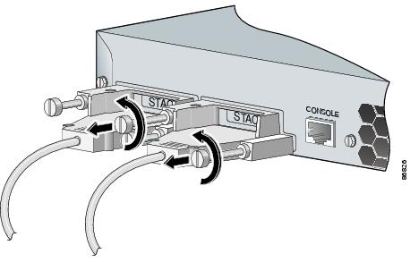
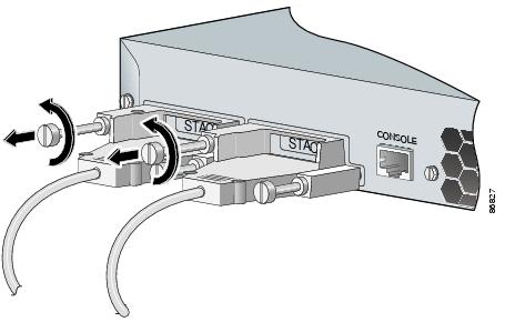
Figure 2-46 Incorrect Removal of a StackWise Cable from a StackWise Port
Installing and Removing SFP Modules
These sections describe how to install and remove SFP modules. SFP modules are inserted into SFP module slots on the front of the Catalyst 3750 switches. These field-replaceable modules provide uplink interfaces.
You can use any combination of SFP modules. See the Catalyst 3750 release notes for the list of SFP modules that the Catalyst 3750 switch supports. Each port must match the wave-length specifications on the other end of the cable, and the cable must not exceed the stipulated cable length for reliable communications. See the "Installation Guidelines" section for cable stipulations for SFP connections.
Use only Cisco SFP modules on the Catalyst 3750 switch. Each SFP module has an internal serial EEPROM that is encoded with security information. This encoding provides a way for Cisco to identify and validate that the SFP module meets the requirements for the switch.
For detailed instructions on installing, removing, and cabling the SFP module, see your SFP module documentation.
Installing SFP Modules into SFP Module Slots
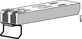
Figure 2-47 shows an SFP module that has a bale-clasp latch.
Removing and installing an SFP module can shorten its useful life. Do not remove and insert SFP modules more often than is absolutely necessary.
Figure 2-47 SFP Module with a Bale-Clasp Latch
To insert an SFP module into the SFP module slot, follow these steps:
Step 1 ![]() Attach an ESD-preventive wrist strap to your wrist and to a bare metal surface on the chassis.
Attach an ESD-preventive wrist strap to your wrist and to a bare metal surface on the chassis.
Step 2 ![]() Find the send (TX) and receive (RX) markings that identify the top side of the SFP module.
Find the send (TX) and receive (RX) markings that identify the top side of the SFP module.
Note ![]() On some SFP modules, the send and receive (TX and RX) markings might be replaced by arrows that show the direction of the connection, either send or receive (TX or RX).
On some SFP modules, the send and receive (TX and RX) markings might be replaced by arrows that show the direction of the connection, either send or receive (TX or RX).
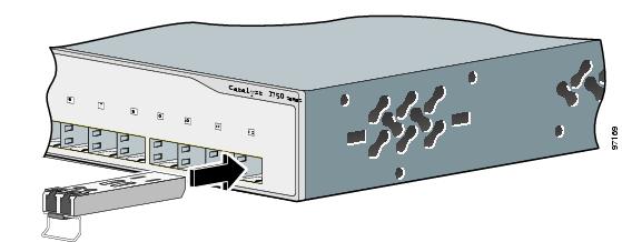
Step 3 ![]() Align the SFP module in front of the slot opening.
Align the SFP module in front of the slot opening.
Step 4 ![]() Insert the SFP module into the slot until you feel the connector on the module snap into place in the rear of the slot.
Insert the SFP module into the slot until you feel the connector on the module snap into place in the rear of the slot.
Figure 2-48 Installing an SFP Module into an SFP Module Slot
Step 5 ![]() For fiber-optic SFP modules, remove the dust plugs from the optical ports, and store them for later use.
For fiber-optic SFP modules, remove the dust plugs from the optical ports, and store them for later use.
Step 6 ![]() Insert the cable connector into the SFP module:
Insert the cable connector into the SFP module:
•![]() For fiber-optic SFP modules, insert the LC or MT-RJ cable connector into the SFP module.
For fiber-optic SFP modules, insert the LC or MT-RJ cable connector into the SFP module.
•![]() For copper SFP modules, insert the RJ-45 cable connector into the SFP module.
For copper SFP modules, insert the RJ-45 cable connector into the SFP module.
Note ![]() When you connect to 1000BASE-T SFP modules, be sure to use a twisted four-pair, Category 5 or later cable.
When you connect to 1000BASE-T SFP modules, be sure to use a twisted four-pair, Category 5 or later cable.
Removing SFP Modules from SFP Module Slots
To remove an SFP module from a module slot, follow these steps:
Step 1 ![]() Attach an ESD-preventive wrist strap to your wrist and to a bare metal surface on the chassis.
Attach an ESD-preventive wrist strap to your wrist and to a bare metal surface on the chassis.
Step 2 ![]() Disconnect the cable from the SFP module.
Disconnect the cable from the SFP module.

Tip ![]() For reattachment, note which cable connector plug is send (TX) and which is receive (RX).
For reattachment, note which cable connector plug is send (TX) and which is receive (RX).
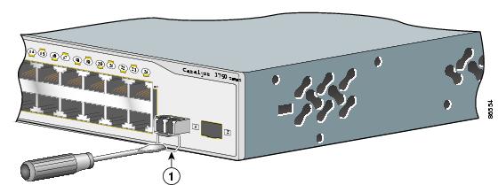
Step 3 ![]() Unlock and remove the SFP module, as shown in Figure 2-49.
Unlock and remove the SFP module, as shown in Figure 2-49.
If the module has a bale-clasp latch, pull the bale out and down to eject the module. If the bale-clasp latch is obstructed and you cannot use your index finger to open it, use a small, flat-blade screwdriver or other long, narrow instrument to open the bale-clasp latch.
Figure 2-49 Removing a Bale-Clasp Latch SFP Module by Using a Flat-Blade Screwdriver
|
|
Bale clasp |
|
Warning |
Step 4 ![]() Grasp the SFP module between your thumb and index finger, and carefully remove it from the module slot.
Grasp the SFP module between your thumb and index finger, and carefully remove it from the module slot.
Step 5 ![]() For fiber-optic SFP modules, insert a dust plug into the optical ports of the SFP module to keep the optical interfaces clean.
For fiber-optic SFP modules, insert a dust plug into the optical ports of the SFP module to keep the optical interfaces clean.
Step 6 ![]() Place the removed SFP module in an antistatic bag or other protective environment.
Place the removed SFP module in an antistatic bag or other protective environment.
Installing and Removing XENPAK Modules (Catalyst 3750G-16TD Switch)
These sections describe how to install and remove XENPAK modules:
•![]() Removing SFP Modules from SFP Module Slots
Removing SFP Modules from SFP Module Slots
XENPAK modules are inserted into the XENPAK module slot on the front panel of the Catalyst 3750G-16TD switch. These field-replaceable transceiver modules provide 10-Gigabit interfaces.
Note ![]() The 10-Gigabit Ethernet XENPAK modules are referred to as 10-Gigabit Ethernet module ports in the switch software documentation.
The 10-Gigabit Ethernet XENPAK modules are referred to as 10-Gigabit Ethernet module ports in the switch software documentation.
See the Catalyst 3750 release notes for the list of XENPAK modules that the Catalyst 3750G-16TD switch supports. Use only Cisco XENPAK modules on the Catalyst 3750G-16TD switch. Each XENPAK module has an internal serial EEPROM that is encoded with security information. This encoding provides a way for Cisco to identify and validate that the XENPAK module meets the requirements for the switch.
See Table B-2 for cable requirements for XENPAK module connections. For detailed instructions on installing, removing, cabling, and troubleshooting the XENPAK module, see your XENPAK module documentation.
Installing a XENPAK Module
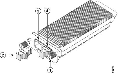
Figure 2-50 shows a XENPAK module.
Figure 2-50 XENPAK Module
|
|
Captive installation screw |
|
Sending optical bore |
|
|
Optical bore dust plug |
|
Receiving optical bore |
To insert a XENPAK module, follow these steps:
Step 1 ![]() Attach an ESD-preventive wrist strap to your wrist and to a bare metal surface on the chassis.
Attach an ESD-preventive wrist strap to your wrist and to a bare metal surface on the chassis.
Step 2 ![]() Remove the two Phillips-head retaining screws from the XENPAK module slot cover, and store them for later use.
Remove the two Phillips-head retaining screws from the XENPAK module slot cover, and store them for later use.
Step 3 ![]() Remove the cover, as shown in Figure 2-51.
Remove the cover, as shown in Figure 2-51.
Figure 2-51 Removing the XENPAK Module Slot Cover
|
|
Phillips-head screw |
|
Module slot cover |
Step 4 ![]() Remove the XENPAK module from the protective packaging.
Remove the XENPAK module from the protective packaging.
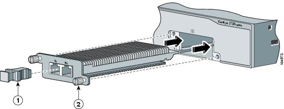
Step 5 ![]() Align the XENPAK module with the guide rails inside the module slot, and slide the module into the opening until the back of the XENPAK faceplate is flush with the switch faceplate. (See Figure 2-52.)
Align the XENPAK module with the guide rails inside the module slot, and slide the module into the opening until the back of the XENPAK faceplate is flush with the switch faceplate. (See Figure 2-52.)
Figure 2-52 Installing a XENPAK Module in the Catalyst 3750G-16TD Switch
|
|
Optical bore dust plug |
|
Captive installation screw |
Step 6 ![]() Secure the XENPAK module in place by tightening the two captive installation screws. Do not overtighten the captive screws.
Secure the XENPAK module in place by tightening the two captive installation screws. Do not overtighten the captive screws.
Removing a XENPAK Module
To remove a XENPAK module, follow these steps:
Step 1 ![]() Attach an ESD-preventive wrist strap to your wrist and to a bare metal surface on the chassis.
Attach an ESD-preventive wrist strap to your wrist and to a bare metal surface on the chassis.
Step 2 ![]() Disconnect the cable from the XENPAK module. For fiber-optic modules, install the optical bore dust plugs.
Disconnect the cable from the XENPAK module. For fiber-optic modules, install the optical bore dust plugs.
Step 3 ![]() Loosen the two captive installation screws that secure the XENPAK module in the slot.
Loosen the two captive installation screws that secure the XENPAK module in the slot.
Step 4 ![]() Carefully pull on the two captive installation screws to disconnect the XENPAK module from the slot.
Carefully pull on the two captive installation screws to disconnect the XENPAK module from the slot.
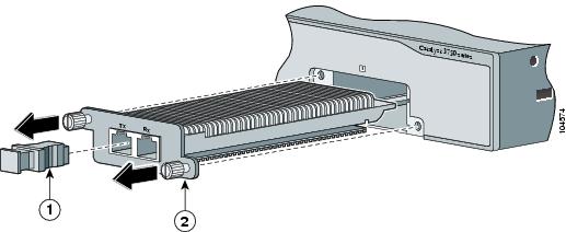
Step 5 ![]() Grasp the edges of the XENPAK module, and carefully slide it out of the slot, as shown in Figure 2-53.
Grasp the edges of the XENPAK module, and carefully slide it out of the slot, as shown in Figure 2-53.
Figure 2-53 Removing a XENPAK Module
|
|
Optical bore dust plug |
|
Captive installation screw |
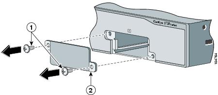
Step 6 ![]() Use two Phillips-head screws to attach the XENPAK module slot cover to the switch front panel, as shown in Figure 2-54.
Use two Phillips-head screws to attach the XENPAK module slot cover to the switch front panel, as shown in Figure 2-54.
|
Warning |
Figure 2-54 Replacing the XENPAK Module Slot Cover

|
|
Phillips-head screw |
|
Module slot cover |
Connecting to the 10/100 and 10/100/1000 Ports
The switch 10/100 and 10/100/1000 ports configure themselves to operate at the speed of attached devices. If the attached ports do not support autonegotiation, you can explicitly set the speed and duplex parameters. Connecting devices that do not autonegotiate or that have their speed and duplex parameters manually set can reduce performance or result in no linkage.
To maximize performance, choose one of these methods for configuring the Ethernet ports:
•![]() Let the ports autonegotiate both speed and duplex.
Let the ports autonegotiate both speed and duplex.
•![]() Set the port speed and duplex parameters on both ends of the connection.
Set the port speed and duplex parameters on both ends of the connection.
|
Warning |
You can configure the 10/100 and 10/100/1000 PoE ports on the switch to either automatically provide PoE when a Cisco IP Phone, Cisco Aironet Access Point, or end device compliant with IEEE 802.3af is connected. Alternatively, you can configure them to never provide PoE, even if an IP phone or an access point is connected. The default setting is Auto. To prevent ESD damage, follow your normal board and component handling procedures.
Use the guidelines in Table 2-1 to select the correct cable for connecting the switch 10/100 and 10/100/1000 ports to other devices. See the "Cable and Adapter Specifications" section for cable-pinout descriptions.
|
|
|
|
|---|---|---|
Switch to switch |
Yes |
No |
Switch to hub |
Yes |
No |
Switch to computer |
No |
Yes |
Switch to router |
No |
Yes |
Switch to IP phone |
No |
Yes |
1 100BASE-TX and 1000BASE-T traffic requires twisted four-pair, Category 5 or higher cable. 10BASE-T traffic can use Category 3 or Category 4 cable. |
You can use the mdix auto interface configuration command in the CLI to enable the automatic medium-dependent interface crossover (auto-MDIX) feature. When the auto-MDIX feature is enabled, the switch detects the required cable type for copper Ethernet connections and configures the interfaces accordingly. Therefore, you can use either a crossover or a straight-through cable for connections to a copper 10/100, 10/100/1000, or 1000BASE-T SFP module port on the switch, regardless of the type of device on the other end of the connection.
The auto-MDIX feature is enabled by default on switches running Cisco IOS Release 12.2(18)SE or later. For releases between Cisco IOS Release 12.1(14)EA1 and 12.2(18)SE, the auto-MDIX feature is disabled by default. For configuration information for this feature, see the switch software configuration guide or the switch command reference.
Follow these steps to connect to 10BASE-T, 100BASE-TX or 1000BASE-T devices:
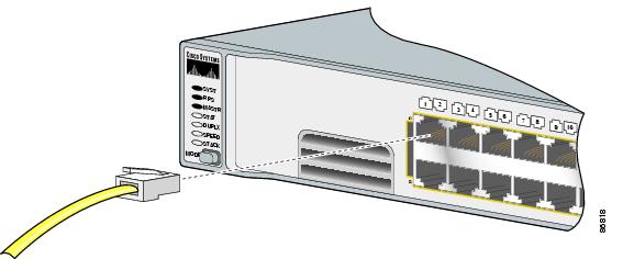
Step 1 ![]() When you connect the switch to workstations, servers, routers, and Cisco IP Phones, connect a straight-through cable to an RJ-45 connector on the front panel. (See Figure 2-55.) When you connect the switch to other switches or to repeaters, use a crossover cable. (See the "Cable and Adapter Specifications" section for cable-pinout descriptions.)
When you connect the switch to workstations, servers, routers, and Cisco IP Phones, connect a straight-through cable to an RJ-45 connector on the front panel. (See Figure 2-55.) When you connect the switch to other switches or to repeaters, use a crossover cable. (See the "Cable and Adapter Specifications" section for cable-pinout descriptions.)
When you connect a switch to 1000BASE-T-compatible devices, be sure to use a twisted four-pair, Category 5 or later cable.
You can connect the Catalyst 3750 switch to a Cisco IP Phone through a straight-through, twisted four-pair Category 5 or later cable. The rear panel of the Cisco IP Phone might have more than one RJ-45 connector. Use the LAN-to-phone connector to connect the Cisco IP phone to the switch. See the Cisco IP Phone documentation for more information about connecting devices to it.
Note ![]() Many legacy powered devices, including older Cisco IP phones and access points that do not fully support IEEE 802.3af, might not support PoE when connected to the switches by a crossover cable.
Many legacy powered devices, including older Cisco IP phones and access points that do not fully support IEEE 802.3af, might not support PoE when connected to the switches by a crossover cable.
Step 2 ![]() Connect the other end of the cable to an RJ-45 connector on the other device. The port LED turns on when both the switch and the connected device have established link.
Connect the other end of the cable to an RJ-45 connector on the other device. The port LED turns on when both the switch and the connected device have established link.
The port LED is amber while Spanning Tree Protocol (STP) discovers the topology and searches for loops. This process takes about 30 seconds, and then the port LED turns green. If the port LED does not turn on, the device at the other end might not be turned on, or there might be a cable problem or a problem with the adapter installed in the attached device. See Chapter 3 "Troubleshooting," for solutions to cabling problems.
Step 3 ![]() Reconfigure and reboot the connected device if necessary.
Reconfigure and reboot the connected device if necessary.
Step 4 ![]() Repeat Steps 1 through 3 to connect each device.
Repeat Steps 1 through 3 to connect each device.
Figure 2-55 Connecting to an Ethernet Port
Connecting to an SFP Module
This section describes how to connect to SFP modules.
•![]() For instructions on how to connect to fiber-optic SFP modules, see the "Connecting to 1000BASE-T SFP Modules" section.
For instructions on how to connect to fiber-optic SFP modules, see the "Connecting to 1000BASE-T SFP Modules" section.
•![]() For instructions on how to connect to 1000BASE-T SFP modules, see the "Connecting to 1000BASE-T SFP Modules" section.
For instructions on how to connect to 1000BASE-T SFP modules, see the "Connecting to 1000BASE-T SFP Modules" section.
•![]() For instructions on how to install or remove an SFP module, see the "Installing and Removing SFP Modules" section.
For instructions on how to install or remove an SFP module, see the "Installing and Removing SFP Modules" section.
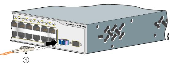
Connecting to a Fiber-Optic SFP Module
Follow these steps to connect a fiber-optic cable to an SFP module:
|
Warning |
Before you connect the switch to the SFP module, be sure that you understand the port and cabling stipulations in "Installation Guidelines" section and in the "SFP Module Slots" section.
Step 1 ![]() Remove the rubber plugs from the module port and fiber-optic cable, and store them for future use.
Remove the rubber plugs from the module port and fiber-optic cable, and store them for future use.
Step 2 ![]() Insert one end of the fiber-optic cable into the SFP module port (see Figure 2-56).
Insert one end of the fiber-optic cable into the SFP module port (see Figure 2-56).
Step 3 ![]() Insert the other cable end into a fiber-optic receptacle on a target device.
Insert the other cable end into a fiber-optic receptacle on a target device.
Step 4 ![]() Observe the port status LED.
Observe the port status LED.
•![]() The LED turns green when the switch and the target device have an established link.
The LED turns green when the switch and the target device have an established link.
•![]() The LED turns amber while the STP discovers the network topology and searches for loops. This process takes about 30 seconds, and then the port LED turns green.
The LED turns amber while the STP discovers the network topology and searches for loops. This process takes about 30 seconds, and then the port LED turns green.
•![]() If the LED is off, the target device might not be turned on, there might be a cable problem, or there might be problem with the adapter installed in the target device. See Chapter 3 "Troubleshooting," for solutions to cabling problems.
If the LED is off, the target device might not be turned on, there might be a cable problem, or there might be problem with the adapter installed in the target device. See Chapter 3 "Troubleshooting," for solutions to cabling problems.
Figure 2-56 Connecting to an SFP Module Port
|
|
LC connector |
Step 5 ![]() If necessary, reconfigure and restart the switch or target device.
If necessary, reconfigure and restart the switch or target device.
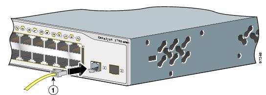
Connecting to 1000BASE-T SFP Modules
Follow these steps to connect a Category 5 cable to a 1000BASE-T SFP module port (see Figure 2-57):
Step 1 ![]() When you connect the switch to servers, workstations, and routers, insert a four twisted-pair, straight-through cable in the RJ-45 connector. When you connect the switch to other switches or repeaters, insert a four twisted-pair, crossover cable.
When you connect the switch to servers, workstations, and routers, insert a four twisted-pair, straight-through cable in the RJ-45 connector. When you connect the switch to other switches or repeaters, insert a four twisted-pair, crossover cable.
Note ![]() When you connect the switch to a 1000BASE-T device, be sure to use a four twisted-pair, Category 5 or higher cable.
When you connect the switch to a 1000BASE-T device, be sure to use a four twisted-pair, Category 5 or higher cable.
Figure 2-57 Connecting to an SFP Module Port
|
|
RJ-45 connector |
Step 2 ![]() Insert the other cable end in an RJ-45 connector on a target device.
Insert the other cable end in an RJ-45 connector on a target device.
Step 3 ![]() Observe the port status LED.
Observe the port status LED.
•![]() The LED turns green when the switch and the target device have an established link.
The LED turns green when the switch and the target device have an established link.
•![]() The LED turns amber while the STP discovers the network topology and searches for loops. This process takes about 30 seconds, and then the port LED turns green.
The LED turns amber while the STP discovers the network topology and searches for loops. This process takes about 30 seconds, and then the port LED turns green.
•![]() If the LED is off, the target device might not be turned on, there might be a cable problem, or there might be problem with the adapter installed in the target device. See Chapter 3 "Troubleshooting," for solutions to cabling problems.
If the LED is off, the target device might not be turned on, there might be a cable problem, or there might be problem with the adapter installed in the target device. See Chapter 3 "Troubleshooting," for solutions to cabling problems.
Step 4 ![]() If necessary, reconfigure and restart the switch or target device.
If necessary, reconfigure and restart the switch or target device.
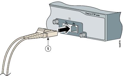
Connecting to a XENPAK Module
The 10-Gigabit Ethernet XENPAK modules are referred to as 10-Gigabit Ethernet module ports in the switch software documentation.
Make sure that the XENPAK module is fully inserted into the module slot and that the captive installation screws are fully tightened before attaching the fiber-optic interface cable connector to the XENPAK module connector.
Follow these steps to connect a fiber-optic cable to a XENPAK module:
|
Warning |
Step 1 ![]() Remove the rubber plugs from the XENPAK module ports and the fiber-optic cable, and store them for future use.
Remove the rubber plugs from the XENPAK module ports and the fiber-optic cable, and store them for future use.
Step 2 ![]() Align the fiber-optic cable SC connector with the XENPAK module connector, so that transmit (TX) on the cable meets receive (RX) on the XENPAK module connector, and RX on the cable meets TX on the XENPAK module.
Align the fiber-optic cable SC connector with the XENPAK module connector, so that transmit (TX) on the cable meets receive (RX) on the XENPAK module connector, and RX on the cable meets TX on the XENPAK module.
Step 3 ![]() Insert the fiber-optic cable connector into the XENPAK module ports (see Figure 2-58).
Insert the fiber-optic cable connector into the XENPAK module ports (see Figure 2-58).
Step 4 ![]() Insert the other cable end into a fiber-optic receptacle on a target device.
Insert the other cable end into a fiber-optic receptacle on a target device.
Step 5 ![]() Observe the XENPAK module port status LED.
Observe the XENPAK module port status LED.
•![]() The LED turns green when the switch and the target device have an established link.
The LED turns green when the switch and the target device have an established link.
•![]() The LED turns amber while the STP discovers the network topology and searches for loops. This process takes about 30 seconds, and then the port LED turns green.
The LED turns amber while the STP discovers the network topology and searches for loops. This process takes about 30 seconds, and then the port LED turns green.
•![]() If the LED is off, the target device might not be turned on, there might be a cable problem, or there might be problem with the adapter installed in the target device. See Chapter 3 "Troubleshooting," for solutions to cabling problems.
If the LED is off, the target device might not be turned on, there might be a cable problem, or there might be problem with the adapter installed in the target device. See Chapter 3 "Troubleshooting," for solutions to cabling problems.
Figure 2-58 Connecting to a XENPAK Module Port
|
|
SC connector |
Step 6 ![]() If necessary, reconfigure and restart the switch or target device.
If necessary, reconfigure and restart the switch or target device.
Where to Go Next
If the default configuration is satisfactory, the switch needs no further configuration. You can use any of these management options to change the default configuration:
•![]() Start the device manager, which is in the switch memory, to manage individual and standalone switches. This is an easy-to-use web interface that offers quick configuration and monitoring. You can access the device manager from anywhere in your network through a web browser. For more information, see the device manager online help.
Start the device manager, which is in the switch memory, to manage individual and standalone switches. This is an easy-to-use web interface that offers quick configuration and monitoring. You can access the device manager from anywhere in your network through a web browser. For more information, see the device manager online help.
•![]() Start the Network Assistant application, which is described in the Getting Started with Cisco Network Assistant guide. Through this GUI, you can configure and monitor a switch cluster or an individual switch.
Start the Network Assistant application, which is described in the Getting Started with Cisco Network Assistant guide. Through this GUI, you can configure and monitor a switch cluster or an individual switch.
•![]() Use the CLI to configure the switch as a member of a cluster or as an individual switch from the console. See the Catalyst 3750 Switch Command Reference on Cisco.com for information on using the CLI with a Catalyst 3750 switch.
Use the CLI to configure the switch as a member of a cluster or as an individual switch from the console. See the Catalyst 3750 Switch Command Reference on Cisco.com for information on using the CLI with a Catalyst 3750 switch.
•![]() Start an SNMP application such as the CiscoView application.
Start an SNMP application such as the CiscoView application.
 Feedback