Feedback
Table Of Contents
Port Mode and Port Status LEDs
Interpreting LEDs after a Mode Change
High-Performance Client/Server Workgroup
Overview
The 2900 XL series switches are workgroup Ethernet switches that supply autosensing 10BaseT or 100BaseT connections on all ports. Expansion slots on Catalyst 2912MF XL and 2924M XL switches supply Gigabit Ethernet and ATM connections. The 2900 XL switches can be deployed as backbone switches aggregating 10/100BaseT traffic from other switches and hubs or in mixed configurations connecting hubs, switches, servers, and desktops.
This chapter is a functional overview of 2900 XL switches. The following topics briefly describe the components and features that are shared by all switches in the series:
•
Switch features
•
•
•
Switch Features
The 2900 XL switches are members of an extended network system of stackable, modular LAN and WAN products that increase LAN performance, connect remote offices and users, and provide secure access.
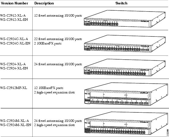
Figure 1-1 shows the five versions of the 2900 XL switch and lists their key features. Switches running standard software are designated by the letter A, and switches running Enterprise Edition Software are designated by the letters EN.
Figure 1-1 Catalyst 2900 Series XL Switches
Front-Panel Description
The front panel of a 2900 XL switch contains the ports, any expansion slots, and the LEDs (see Figure 1-1). This section describes these features.
10/100 Ports
The10/100 ports on a 2900 XL switch are internally switched to all other switch ports and use RJ-45 connectors and Category 5 cabling. They operate at either 10 or 100 Mbps in full or half duplex. For autonegotiation with other devices, the ports are IEEE 802.3u-compliant.
When connected to another device, a port senses the speed and duplex settings of the attached device and advertises its own capabilities. If the attached device also supports autonegotiation, the switch port negotiates the best connection (that is, the fastest line speed that both devices support and full duplex transmission, if the attached device supports it) and configures itself accordingly. Ports can also be explicitly set to operate in any combination of half duplex, full duplex, 10 Mbps, or 100 Mbps. In all cases, the attached device must be within 100 meters of the switch.
100BaseFX Ports
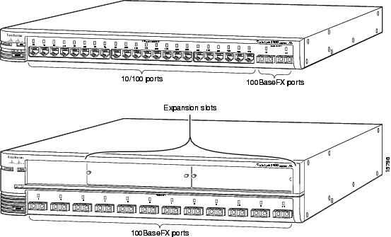
The Catalyst 2924C XL switch has 2 100BaseFX ports, and the Catalyst 2912MF XL switch has 12 100BaseFX ports (see Figure 1-2). These ports use 10/125- or 62.5/125-micron multimode fiber-optic cabling. In full-duplex mode (the default), these ports connect to other 100BaseFX devices over distances of up to 2 kilometers. In half-duplex mode, the ports connect to devices up to 412 meters from the switch.
The 100BaseFX ports default to full-duplex operation and do not autonegotiate.
Figure 1-2 Catalyst 2924C XL and 2912MF XL 100BaseFX Ports
High-Speed Expansion Slots
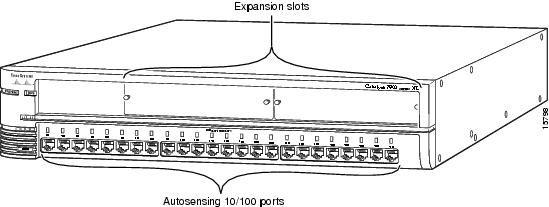
The Catalyst 2912MF XL switch (see Figure 1-2) and the Catalyst 2924M XL (see Figure 1-3) have two high-speed expansion slots for the 2900 XL hot-swappable modules. Each module port is internally switched to other switch ports and is managed through the switch management interfaces.
lists the modules that the expansion slots support.
Table 1-2 Expansion Modules
10/100 Ethernet
WS-X2914-XL
WS-X2914-XL-V
WS-X2922-XL
100 BaseFX
WS-X2922-XL-V
WS-X2924-XL-V
1 Gigabit Ethernet
WS-X2931-XL
ATM
WS-X2971-XL
WS-X2972-XL
WS-X2951-XL
WS-X2961-XL
1 Accommodates modules WS-G5484 =, WS-G5486 =, and WS-X3500-XL=
These modules automatically configure themselves when you insert them in expansion slots and tighten the thumb screws. A power-on self-test (POST) verifies that the module is working properly before it starts forwarding packets.
Modules WS-X2914-XL and WS-X2922-XL support 2048 MAC addresses. If you install one of these modules in a 2924M XL or Catalyst 2912MF XL switch (both of which support 8192 MAC addresses) the module fails POST. You can start the module by restarting the switch with the module installed. After the restart, the addressing capacity of the switch is reduced to 2048 MAC addresses.
See the Catalyst 2900 Series XL Modules Installation Guide and the Catalyst 2900 XL ATM Modules Installation Guide for detailed information on expansion modules for Catalyst 2900 series XL switches.
Figure 1-3 Catalyst 2924M XL
LEDs
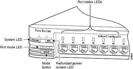
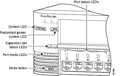
You can use the switch LEDs to monitor switch activity and its performance. and Figure 1-5 show the location of the LEDs and the Mode button you use to select one of the port modes. Changing a port mode changes the information provided by each port status LED.
All of the LEDs described in this section except the utilization meter (UTL) are visible on the Cisco Visual Switch Manager (CVSM) home page and on the Cisco Cluster Manager page if the switch is a cluster member. The Cisco IOS Desktop Switching Software Configuration Guide describes how to use CVSM to manage individual switches and how to use cluster management software to manage multiple switches in a cluster.
Figure 1-4 Catalyst 2912 XL, Catalyst 2924 XL, and Catalyst 2924C XL LEDs
Figure 1-5 Catalyst 2912MF XL and Catalyst 2924M XL LEDs
System LED
The system LED shows whether the system is receiving power and functioning properly. lists the LED colors and their meanings.
Table 1-3 System LED
Off
System is not powered up.
Green
System is operating normally.
Amber
System is receiving power but is not functioning properly.
RPS LED
The RPS LED shows the RPS status. lists the LED colors and their meanings.
Table 1-4 RPS LED
Port Mode and Port Status LEDs
Catalyst series switches have four LED modes, each of which provides different information about a particular port or the switch itself. The Mode button (shown in and ) highlights each mode in sequence. LED modes provide the following information:
STAT
The port status. This is the default mode.
UTL
The current bandwidth in use by the switch.
FDUP
The port duplex mode: full duplex or half duplex.
100
The port operating speed: 10 or 100 Mbps.
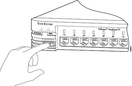
Changing the Port Mode
To change the port mode, press the Mode button (see Figure 1-6) to highlight the mode that you want. Release the button to enable the highlighted function.
Figure 1-6 Changing the Port Mode
Interpreting LEDs after a Mode Change
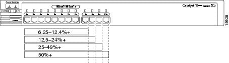
When you change the port mode, the meaning of the LED colors changes. explains how to interpret LED colors.
Figure 1-7 shows bandwidth utilization percentages displayed by the right-most LEDs.
Figure 1-7 Bandwidth Utilization
Expansion Slot LEDs
Expansion slot LEDs (illustrated in ) show the status of installed modules. The LEDs are numbered 1 (left slot) and 2 (right slot). lists LED colors and their meanings.
Table 1-6 Expansion Slot LEDs
Off
No module is installed.
Green
Module is operating normally.
Amber
Module failed POST and should be replaced.
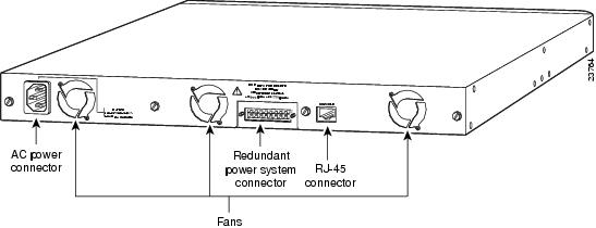
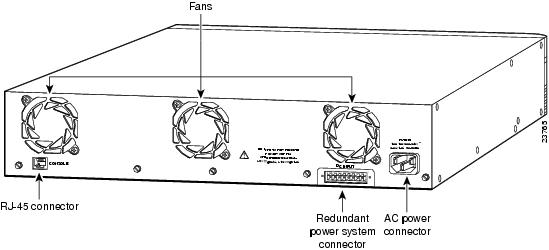
Rear-Panel Description
Switch rear panels have an AC power connector, a Redundant Power System (RPS) connector, an RJ-45 console port, and fans (see Figure 1-8 and ). These components are described in this section.
Power Connectors
You can provide power to the switch either by connecting the Cisco RPS to the RPS connector on the switch or by using the internal power supply. The internal power supply is an autoranging unit that supports input voltages between 100 and 240 VAC. If you plan to use the internal power supply, use the supplied AC power cord to connect the AC power connector to an AC power outlet.
Note
Warning
The RPS can provide a quasi-redundant power source for four external devices that use up to 150W DC each. You can use a one-to-one cable (one connector at each cable end) to connect four external devices to the four DC output power modules. The power source is quasi-redundant because there are two AC input power modules for the Cisco RPS and one DC output power module for each external device. The AC input to the Cisco RPS is fully redundant, but the DC output to the external devices is not.
For more information on the Cisco RPS, refer to the Cisco RPS documentation.
Console Port
You can use the console port and the supplied rollover cable to connect a 2900 XL switch to a PC or terminal. For the data characteristics of the console port, see the "Connecting a Terminal or PC to the Console Port" section.
Figure 1-8 Rear Panel: Catalyst 2912 XL, Catalyst 2924 XL, and Catalyst 2924C XL
Figure 1-9 Rear Panel: Catalyst 2924M XL and Catalyst 2912MF XL
Management Options
Catalyst switches offer several management options:
•
Using CVSM, you can use a Web browser to manage a single switch, display network maps, and monitor the network. See the Cisco IOS Desktop Switching Software Configuration Guide and the online help in the CVSM application for information about this software.
•
All 2900 XL switches shown in can be a member of a cluster and can be managed by using a Web browser and cluster management software. These switches can also be the command switch of a cluster if you install the software upgrade (see the Release Notes for the Catalyst 2900 Series XL and 3500 Series XL Cisco IOS
Release 11.2 (8) SA6 for upgrade procedures).
Note
3500 Series XL Cisco IOS Release 11.2(8) SA6 for procedures.
•
With the Cisco IOS CLI, you can manage 2900 XL switches using traditional command entries. You can access the CLI by connecting a PC or terminal directly to the console port on the rear panel of the switch. If the switch is attached to your network, you can use a Telnet connection to manage the switch from a remote location. See the Cisco IOS Desktop Switching Software Configuration Guide for information.
•
The CiscoView application is a device-management application that you can use to click on a switch image to set configuration parameters and to view switch status and performance information. The CiscoView application, which you purchase separately, can be a standalone application or part of an Simple Network Management Protocol (SNMP) network-management platform. See the documentation that came with your CiscoView application for information.
•
You can manage switches by using an SNMP-compatible management station running platforms such as HP OpenView and SunNet Manager. The switch supports a comprehensive set of MIB extensions and MIB II, the IEEE 802.1D bridge MIB, and four Remote Monitoring (RMON) groups. See the documentation that came with your SNMP application for information.
Deployment Strategies
The examples in this section show ways in which you might deploy 2900 XL switches in your network.
•
•
•
•
High-Performance Client/Server Workgroup
shows a Catalyst 2924M XL switch connecting workstations, 100BaseTX hubs, and servers in a topology for client/server applications. The links to the 100BaseTX servers and workstations can be full duplex. A repeater does not support full-duplex transmission, so the links to the 100BaseTX repeaters are always half duplex.
Figure 1-10 Catalyst 2924M XL in a High-Performance Client/Server Workgroup
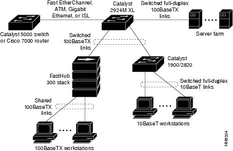
Wiring Closet Aggregator
Figure 1-11 shows a Catalyst 2924M XL switch connecting 100BaseTX and 10BaseT devices. In this topology, the switch is in the middle of the network and can provide connectivity to a mixture of hubs, switches, and servers.
Figure 1-11 Catalyst 2924M XL in a Wiring Closet
Power Workgroup
Figure 1-12 shows a Catalyst 2924C XL or 2924 XL with a 100BaseT uplink and 10/100 connections to individual workstations.
Figure 1-12 Catalyst 2924C XL or Catalyst 2924 XL in a Power Workgroup Configuration
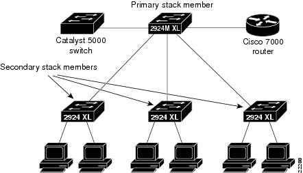
Star Topology Stack
Figure 1-13 shows four 2900 XL switches in a star topology. You could manage these switches by using CVSM and Cisco Switch Network View. shows a Cisco router, a Catalyst 5000 series switch, and four 2900 XL switches connecting desktops. For information on managing a cluster of switches, see the Cisco IOS Desktop Switching Software Configuration Guide.
Figure 1-13 Catalyst 2924M XL in a Star Topology Stack