Feedback
Table Of Contents
Straight-Through and Crossover Cable Pinouts
Connectors and Cables
This appendix describes the cables, connectors, and adapters that can connect to 2900 XL switch ports.
Note
The Catalyst 2900 Series XL Modules Installation Guide and the Catalyst
2900 Series XL ATM Modules Installation Guide describe expansion module cables and connectors.10/100 Ports
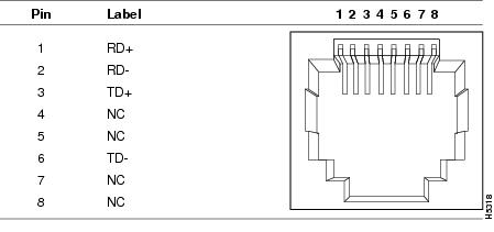
The 10/100 ports use standard RJ-45 connectors and Ethernet pinouts with internal crossovers, as indicated by an X in the port name. These ports have their transmit (TD) and receive (RD) signals internally crossed, so that a straight-through cable and adapter can be attached to the port. Figure B-1 shows the pinout on the port connector.
When connecting the 10/100 ports to compatible servers and workstations, you must use a straight-through 10BaseT and 100BaseTX cable ( illustrates straight-through cable schematics). When connecting to other switches or repeaters, you must use a crossover cable ( illustrates crossover cable schematics).
Note
Figure B-1 10/100 Pinout
100BaseFX Ports
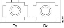
100BaseFX ports use duplex SC connectors, as shown in Figure B-2. These ports use 10/125- or 62.5/125-micron multimode fiber-optic cabling.
Figure B-2 100BaseFX SC Connector
Straight-Through and Crossover Cable Pinouts
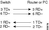
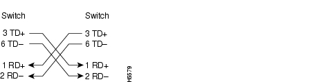
The schematics of crossover and straight-through cables are shown in Figure B-3 and Figure B-4.
Figure B-3 Straight-Through Cable Schematic
Figure B-4 Crossover Cable Schematic
Console Port
The console port uses an 8-pin RJ-45 connector, as shown in Figure B-6 and described in . The supplied RJ-45-to-RJ-45 rollover cable and adapters connect the console port of the switch to a console PC or terminal. The following sections describe the rollover cable and adapters for the console port.
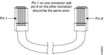
Identifying a Rollover Cable
You can identify a rollover cable by comparing the two modular ends of the cable. Hold the cable ends side-by-side, with the tab at the back. The wire connected to the pin on the outside of the left plug should be the same color as the wire connected to the pin on the outside of the right plug (see Figure B-5).
Figure B-5 Identifying a Rollover Cable
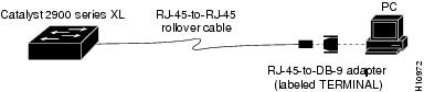
Connecting to a PC
Use the thin, flat, RJ-45-to-RJ-45 rollover cable and RJ-45-to-DB-9 female DTE adapter (both provided) to connect the console port to a PC running terminal-emulation software. Figure B-6 shows how to connect the console port to a PC. lists the pinouts for the console port, the RJ-45-to-RJ-45 rollover cable, and the RJ-45-to-DB-9 female DTE adapter.
Figure B-6 Connecting the Console Port to a PC
Connecting to a Terminal
Use the thin, flat, RJ-45-to-RJ-45 rollover cable and RJ-45-to-DB-25 female DTE adapter to connect the console port to a terminal. Figure B-7shows how to connect the console port to a terminal. lists the pinouts for the console port, the RJ-45-to-RJ-45 rollover cable, and the RJ-45-to-DB-25 female DTE adapter.
Figure B-7 Connecting the Console Port to a Terminal