Feedback
Table Of Contents
Installing the Switch in a Rack
Removing Screws from the Switch
Attaching the Brackets to the Switch
Attaching the Optional Cable Guide
Installing the Switch on a Wall
Attaching the Brackets to the Switch
Attaching the Switch to a Wall
Installing the Switch on a Table or Shelf
Connecting to the 10/100 Ports
Connecting to the 100BaseFX Ports
Connecting a Terminal or PC to the Console Port
Installation
This chapter describes how to install your Catalyst 2900 XL switch and interpret the power-on self-test (POST) that ensures proper operation. Read the topics and perform these procedures in the order that they are presented:
•
Package Contents
•
•
•
•
•
•
•
•
Note
2900 Series XL ATM Modules Installation and Configuration Guide for information on Catalyst 2900 series XL expansion modules.Package Contents
When you unpack the switch, be sure that the package contains the items in the following list. If any items are missing, notify your authorized Cisco sales representative:
•
•
•
•
•
•
•
•
•
•
•
•
•
•
•
•
•
Warnings
These warnings are translated into several languages in "."
Warning
Warning
Warning
Warning
Warning
Warning
Warning
Warning
Warning
Warning
Warning
Warning
Warning
Warning
Warning
Warning
EMC Regulatory Statements
U.S.A.
U.S. regulatory information for this product is in the front matter of this manual.
Taiwan
Installation Guidelines
When determining where to place the switch, be sure to observe the guidelines listed below (see "," for detailed specifications):
•
100 meters.•
•
•
•
•
•
•
•
•
Note
•
Installation Procedures
A 2900 XL switch can be installed in a 19-inch or 24-inch standard rack, on a wall, or on a table or shelf. This section contains procedures for installing a switch in each of these locations.
Note
Before you begin the installation, decide how to mount the switch by reviewing the illustrations in this section. If you decide to mount the switch in a rack or on a wall, use the mounting brackets supplied with the switch.
Installing the Switch in a Rack
To install the switch in a 19-inch or 24-inch standard rack, follow the instructions described in these procedures:
•
•
•
•
Removing Screws from the Switch
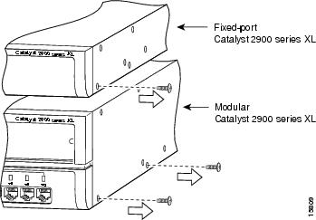
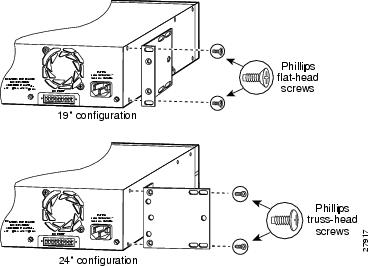
If you plan to install the switch in a rack, you must first remove screws in the switch chassis so that mounting brackets can be attached to the chassis. Figure 2-1 shows how to remove the chassis screws in a fixed-port and a modular port switch.
Figure 2-1 Removing Screws from the Switch
Attaching the Brackets to the Switch
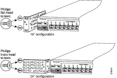
The bracket orientation and screws that you use depend on whether you are attaching the brackets for a 19-inch or 24-inch rack. Use two of the supplied screws to attach each bracket, according to rack size:
•
•
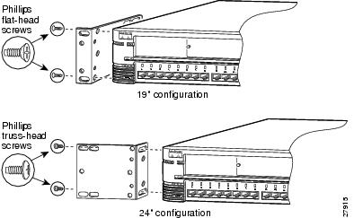
Figure 2-2, , Figure 2-4, and , show how to attach a bracket to one side of the switch. Follow the same steps to attach the second bracket to the opposite side of the switch.
Figure 2-2 Attaching Brackets on Fixed-Port Switches (Front Panel Forward)
Figure 2-3
Attaching Brackets on Modular Switches (Front Panel Forward)
Figure 2-4 Attaching Brackets on Fixed-Port Switches (Rear Panel Forward)
Figure 2-5
Attaching Brackets on Modular Switches (Rear Panel Forward)
Mounting the Switch in a Rack
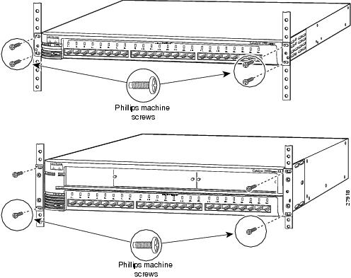
After the brackets are attached to the switch, use the four supplied Phillips machine screws to securely attach the brackets to the rack, as shown in Figure 2-6.
Figure 2-6 Mounting the Fixed-Port and Modular Switch in a Rack
After the switch is mounted in the rack, attach the power cord to the switch. If you are using the Cisco Redundant Power Supply (RPS), see the Cisco documentation that came with your RPS for installation instructions.After the power is connected, the System LED is amber for 2 seconds, and then it flashes green while the switch completes a power-on self-test (POST), described in the "POST Results" section.
Attaching the Optional Cable Guide
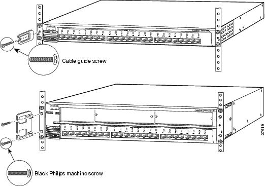
We recommend attaching the cable guides to prevent the cables from obscuring the front panel of the switch and the other devices installed in the rack. If the switch is in a 19-inch or 24-inch rack, you can attach the cable guide to the left or right bracket by using the supplied black screw, as shown in Figure 2-7. The cable guides for the modular switches require two screws.
Figure 2-7 Attaching the Cable Guide in a Fixed-Port and a Modular Switch
Installing the Switch on a Wall
To attach the switch to a wall, follow the procedures in this section:
•
•
Attaching the Brackets to the Switch
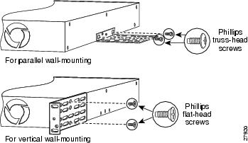
The bracket orientation and the screws you use depend on whether you are attaching the brackets for parallel or vertical wall-mounting. Use two of the supplied screws to attach each bracket, according to the following guidelines:
•
•
Figure 2-8 and show how to attach the brackets to one side of the switch. Follow the same steps to attach the second bracket to the opposite side of the switch.
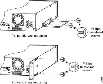
Figure 2-8 Attaching Brackets for Parallel and Vertical Wall-Mounting for Fixed-Port Switches
Figure 2-9 Attaching Brackets for Parallel and Vertical Wall-Mounting for Modular Switches
Attaching the Switch to a Wall
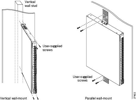
For best support of the switch and cables, make sure the switch is attached securely to a wall stud or to a firmly attached plywood mounting backboard, as shown in Figure 2-10 and Figure 2-11.
Figure 2-10 Attaching the Fixed-Port Switch to a Wall
Figure 2-11 Attaching the Modular Switch to a Wall
After the switch is mounted on the wall, attach the power cord to the switch. If you are using the Cisco RPS, see the Cisco RPS documentation.After the Cisco RPS is connected, the System LED is amber for 2 seconds, and then it flashes green while the switch completes a power-on self-test (POST), described in the "POST Results" section.
Installing the Switch on a Table or Shelf
Follow these steps to install the switch on a table or shelf:
Step 1
Step 2
Step 3
After the power is connected, the System LED is amber for 2 seconds, and then it flashes green while the switch completes a power-on self-test (POST), described in the "POST Results" section.
POST Results
POST (a series of eight power-on self-tests) runs automatically to ensure that the switch functions properly. When the switch begins POST, the port status LEDs turn amber for 2 seconds, and then they turn green. As each test runs, the port LEDs turn off, starting with number 1X. The LEDs for ports 2X to 8X then go off in turn as the system completes a test.
When the POST completes successfully, all port status LEDs are off, indicating that the switch is operational. If a test fails, the port status LED associated with the test turns amber, and the system LED turns amber (see "," for more information).
POST failures are almost always fatal. Call Cisco Systems immediately if your switch does not pass POST.
Connection Procedures
The procedures in this section explain how to connect devices to the 10/100 ports on the 2900 XL switch. For information on installing and connecting to modules in the expansion slots on the Catalyst 2924M XL and 2912MF XL switches, see the Catalyst 2900 Series XL Modules Installation Guide and the Catalyst 2900 Series XL ATM Modules Installation and Configuration Guide.
Connecting to the 10/100 Ports
The 10/100 ports configure themselves to operate at the speed of attached devices. If the attached ports do not support autonegotiation, you can explicitly set the speed and duplex parameters.
Connecting devices that do not autonegotiate or devices with manually set speed and duplex parameters can reduce performance or result in link failures between the devices. To maximize performance, choose one of these methods for configuring the 10/100 ports:
•
•
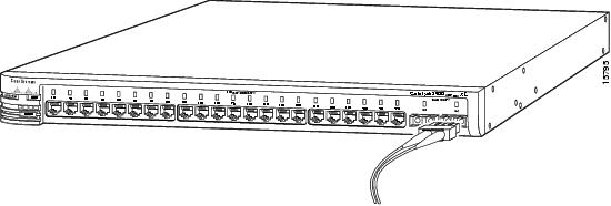
Follow these steps to connect to 10BaseT or 100BaseTX devices:
Step 1
Category 5 cable in a front panel RJ-45 connector, as shown in Figure 2-12.
Note
Step 2
The port status LED is amber while Spanning-Tree Protocol (STP) discovers the topology and searches for loops (this takes about 30 seconds). Then the port status LED turns green.
If the port status LED does not come on, the device at the other end might not be turned on, or there might be a cable problem or a problem with the adapter installed in the attached device. See "," for solutions to cabling problems.
Step 3
Step 4
Figure 2-12 Inserting the RJ-45 Connector in a 10/100 Port
Connecting to the 100BaseFX Ports
Follow these steps to connect to a fixed 100BaseFX ports:
Step 1
Step 2
CautionDo not remove the rubber plugs from the fiber-optic port or the rubber caps from the fiber-optic cable until you are ready to connect the cable. The plugs and caps protect the fiber-optic port and cable from contamination and ambient light.
Figure 2-13 Inserting the SC Connector in a 100BaseFX Port
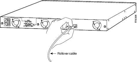
Connecting a Terminal or PC to the Console Port
Use the supplied rollover cable to connect a terminal or PC to the console port. The terminal or PC must support VT100 terminal emulation. The terminal-emulation software—frequently a PC application such as HyperTerminal or Procomm Plus—makes communication between the switch and your PC or terminal possible during the setup program.
Follow these steps to connect the terminal or PC to the switch:
Step 1
Step 2
•
•
•
•
After you have gained access to the switch, you can change the baud rate of the port. See the Cisco IOS Desktop Switching Software Configuration Guide for instructions.
Step 3
Step 4
•
•
Step 5
Step 6
Figure 2-14 Inserting the RJ-45 Connector in the Console Port
IP Address Procedures
You can assign the switch an IP address by two methods:
•
•
This section describes each method.
Note
Using the Setup Program
The switch setup program assigns IP information and creates a default configuration that you can use to operate the switch. To run the setup program, access the switch from the terminal or PC that you connected to the console port. (The "Connecting a Terminal or PC to the Console Port" section explains this procedure.) Later, you can customize the configuration by using Cisco Visual Switch Manager (CVSM) or the command-line interface (CLI).
The first time you access the switch, the setup program prompts you for an IP address, a subnet mask, and the IP address of the default gateway. Contact your system administrator for these numbers:
Follow these steps to assign the IP information to the switch:
Note
Step 1
Continue with configuration dialog? [yes/no]: y
If this prompt does not appear, enter enable, and press Return. Enter setup, and press Return to start the setup program.
Step 2
Enter IP address: ip_address
Step 3
Enter IP netmask: ip_netmask
Step 4
Would you like to enter a default gateway address? [yes]: y
Step 5
Enter router IP address: IP_address
Step 6
Enter host name: host_name
Step 7
Enter enable secret password: <secret_password>
The initial configuration displays:
The following configuration command script was created:
interface VLAN1
ip address IP_address IP_netmask
ip default-gateway IP_address
enable secret 5 $1$jJql$VA6U.6uTjsa56Xx2yy/t30
snmp community private rw
snmp community public ro
!
end
!
Use this configuration? [yes/no]:Step 8
Enter Y, and press Return if the displayed information is correct. If this information is not correct, enter N, press Return, and begin again at Step 2.
When you see the message "Press RETURN to get started," the setup program is complete. You can use your browser and CVSM (or the CLI) to continue the switch management session.
The Cisco IOS Desktop Switching Software Configuration Guide describes how to set a password to protect the switch against unauthorized Telnet access and how to access the switch if you forget the password.
Using a BOOTP Server
If a BOOTP server is accessible to the switch from any of its ports, you can use BOOTP to assign IP information to the switch. The BOOTP server must contain a list of physical MAC addresses and corresponding IP addresses. Other IP information that is part of the switch setup, such as the corresponding subnet mask and default gateway address, can also be stored on the server, but this information is optional.
When a switch starts and no IP address is assigned, it transmits a BOOTP broadcast requesting a mapping for its physical MAC address; this request is sent to all ports with a physical connection to the switch. A valid response must contain an IP address and can contain the subnet mask and default gateway address. If the switch receives a valid BOOTP response immediately, the remainder of the system protocol suite is activated.
A valid BOOTP response sets the IP information in the running configuration, but this information is not updated in the saved configuration in Flash memory. To update the IP information in the saved-configuration file, log in to the CLI, and enter the write memory command. This command records the IP information in the saved-configuration file, and no BOOTP request is required when the switch is reset.
Default Configuration
After you assign IP information, the switch can operate with the default configuration shown in .
Table 2-1 Default Configuration Values
Switch IP address, subnet mask, and default gateway
User-assigned values entered in the setup program.CDP1
Enabled.
ARP2
Enabled.
Static address assignment
None assigned.
Network View
Always available.
VLAN3 membership
All ports are static-access ports in VLAN 1.
Autonegotiation of duplex mode
Enabled.
Autonegotiation of port speeds
Enabled.
Broadcast storm control
Disabled.
Flooding unknown unicast and multicast packets
Enabled.Network port
Disabled.
CGMP4
Enabled.
Spanning-Tree Protocol
Enabled.
Port grouping
None assigned.
SPAN port monitoring
Disabled.
Console, buffer, and file logging
Disabled.
Password
None.
Addressing security
Disabled.
Trap manager
0.0.0.0.
Community strings
public.
Port security
Disabled.
1 CDP = Cisco Discovery Protocol
2 ARP = Address Resolution Protocol
3 VLAN = Virtual Local Area Network
4 CGMP = Cisco Group Management Protocol
Where to Go Next
You can operate the switch with the default configuration shown in , or you can use one of the following management options to change the default configuration:
•
•
2900 series XL switches.•
•
•