- Index
- New and Changed Information for Interfaces NX-OS Configuration Guide
- Preface
- Overview
- Configuring Basic Interface Parameters
- Configuring Access and Trunk Interfaces
- Configuring Layer 3 Interfaces
- Configuring Port Channels
- Configuring vPCs
- Configuring IP Tunnels
- IETF RFCs Supported by Cisco NX-OS Interfaces
- Configuration Limits for Cisco NX-OS Interfaces
- Information About the Basic Interface Parameters
- Licensing Requirements
- Guidelines and Limitations
- Configuring the Basic Interface Parameters
- Specifying the Interfaces to Configure
- Configuring the Description
- Configuring the Beacon Mode
- Changing the Bandwidth-Rate Mode
- Configuring the Error-Disabled State
- Configuring the MDIX Parameter
- Configuring the Debounce Timer
- Configuring the Interface Speed and Duplex Mode
- Configuring the Flow Control
- Configuring the MTU Size
- Configuring the Bandwidth
- Configuring the Throughput Delay
- Shutting Down and Activating the Interface
- Configuring the UDLD Mode
- Configuring the Carrier Delay Timer
- Configuring Port Profiles
Configuring Basic Interface Parameters
This chapter describes how to configure the basic interface parameters on the Cisco Nexus 7000 Series NX-OS devices.
This chapter includes the following sections:
- Information About the Basic Interface Parameters
- Licensing Requirements
- Guidelines and Limitations
- Configuring the Basic Interface Parameters
- Verifying the Basic Interface Parameters
- Displaying and Clearing the Interface Counters
- Default Settings
- Additional References
- Feature History for Configuring Basic Interface Parameters

Note![]() To configure the parameters that are specifically used for Layer 2 interfaces (access or trunking interfaces), see Chapter3, “Configuring Layer 2 Interfaces” To configure parameters that are specifically used for Layer 3 interfaces (routed interfaces, subinterfaces, VLAN interfaces, loopback interfaces, and IP tunnels), see Chapter4, “Configuring Layer 3 Interfaces”
To configure the parameters that are specifically used for Layer 2 interfaces (access or trunking interfaces), see Chapter3, “Configuring Layer 2 Interfaces” To configure parameters that are specifically used for Layer 3 interfaces (routed interfaces, subinterfaces, VLAN interfaces, loopback interfaces, and IP tunnels), see Chapter4, “Configuring Layer 3 Interfaces”
Information About the Basic Interface Parameters
This section includes the following topics:
- Description
- Beacon
- MDIX
- Debounce Timer
- Error Disabled
- Rate Mode
- Speed Mode and Duplex Mode
- Flow Control
- Port MTU Size
- Bandwidth
- Throughput Delay
- Administrative Status
- Unidirectional Link Detection Parameter
- Carrier Delay
- Port-Channel Parameters
- Port Profiles
Description
For the Ethernet and management interfaces, you can configure the description parameter to provide a recognizable name for the interface. Using a unique name for each interface allows you to quickly identify the interface when you are looking at a listing of multiple interfaces.
For information on setting the description parameter for port-channel interfaces, see the “Configuring a Port-Channel Description” section. For information on configuring this parameter for other interfaces, see the “Configuring the Description” section.
Beacon
The beacon mode allows you to identify a physical port by flashing its link state LED with a green light. By default, this mode is disabled. To identify the physical port for an interface, you can activate the beacon parameter for the interface.
For information on configuring the beacon parameter, see the “Configuring the Beacon Mode” section.
MDIX
The medium dependent interface crossover (MDIX) parameter enables or disables the detection of a crossover connection between devices. This parameter applies only to copper interfaces. By default, this parameter is enabled.
For information on configuring the MDIX parameter, see the “Configuring the MDIX Parameter” section.
Debounce Timer
The debounce timer delays notification of a link change, which can decrease traffic loss due to network reconfiguration. You can configure the debounce timer separately for each Ethernet port and specify the delay time in milliseconds. By default, this parameter is set for 100 milliseconds.

For information on configuring the debounce-timer parameters, see the “Configuring the Debounce Timer” section.
Error Disabled
A port is in the error-disabled (err-disabled) state when the port is enabled administratively (using the no shutdown command) but disabled at runtime by any process. For example, if UDLD detects a unidirectional link, the port is shut down at runtime. However, because the port is administratively enabled, the port status displays as err-disable. Once a port goes into the err-disable state, you must manually reenable it or you can configure a timeout value that provides an automatic recovery. By default, the automatic recovery is not configured, and by default the err-disable detection is enabled for all causes.
When an interface is in the err-disabled state, use the errdisable detect cause command to find information about the error.
You can configure the automatic error-disabled recovery timeout for a particular error-disabled cause and configure the recovery period.
The errdisable recovery cause command provides an automatic recovery after 300 seconds.
You can use the errdisable recovery interval command to change the recovery period within a range of 30 to 65535 seconds. You can also configure the recovery timeout for a particular err-disable cause
If you do not enable the error-disabled recovery for the cause, the interface stays in the error-disabled state until you enter the shutdown and no shutdown commands. If the recovery is enabled for a cause, the interface is brought out of the error-disabled state and allowed to retry operation once all the causes have timed out. Use the show interface status err-disabled command to display the reason behind the error.
Rate Mode
On a 32-port 10-Gigabit Ethernet module, each set of four ports can handle 10 gigabits per second (Gb/s) of bandwidth. You can use the rate-mode parameter to dedicate that bandwidth to the first port in the set of four ports or share the bandwidth across all four ports.
Table 2-1 identifies the ports that are grouped together to share each 10 Gb/s of bandwidth and which port in the group can be dedicated to utilize the entire bandwidth.
|
|
|
|---|---|
Note![]() All ports in each port group must be part of the same virtual device context (VDC). For more information on VDCs, see the Cisco Nexus 7000 Series NX-OS Virtual Device Context Configuration Guide, Release 4.x.
All ports in each port group must be part of the same virtual device context (VDC). For more information on VDCs, see the Cisco Nexus 7000 Series NX-OS Virtual Device Context Configuration Guide, Release 4.x.
Speed Mode and Duplex Mode
The speed mode and duplex mode are interrelated for each Ethernet and management interface. By default, each of these interfaces autonegotiates its speed and duplex mode with the other interface, but you can change these settings. If you change the settings, be sure to use the same speed and duplex mode setting on both interfaces, or use autonegotiation for at least one of the interfaces. Table 2-2 shows the settings that work for each type of Ethernet and management interface.
|
|
|
|
|
|
|---|---|---|---|---|
Auto1 |
||||
|
|
For information on setting the speed mode and duplex mode for port-channel interfaces, see the “Configuring the Speed and Duplex Settings for a Port-Channel Interface” section. For information on setting the speed and duplex speed for other interfaces, see the “Configuring the Interface Speed and Duplex Mode” section.
Flow Control
When the receive buffer for an Ethernet port that runs 1 Gb/s or faster fills, flow control enables that port to send an IEEE 802.3x pause frame to the transmitting port to request it to stop transmitting data for a specified amount of time. Transmitting ports, running at any speed, can receive the pause frames to stop their transmission of data.
To allow flow control to work between two ports, you must set the corresponding receive and send flow control parameters for both ports as enabled or desired. When you set the parameter to enabled, the send or receive flow-control function is activated regardless of the setting of the other port. When you set the parameter to desired, the send or receive flow-control function is activated if you set the corresponding flow-control state of the other port to enabled or desired. If you set one of the flow control states to disabled, flow control is disabled for that transmission direction. To see how the different port flow-control states affect the link flow-control state, see Table 2-3 .
|
|
|
|
|---|---|---|
|
|
|
|
For information on setting the flow-control parameters, see the “Configuring the Flow Control” section.
Port MTU Size
The maximum transmission unit (MTU) size specifies the maximum frame size that an Ethernet port can process. For transmissions to occur between two ports, you must configure the same MTU size for both ports. A port drops any frames that exceed its MTU size.
By default, each port has an MTU of 1500 bytes, which is the IEEE 802.3 standard for Ethernet frames. Larger MTU sizes are possible for more efficient processing of data with less overhead. The larger frames, called jumbo frames, can be up to 9216 bytes in size, which is also the default system jumbo MTU size.
On a Layer 3 interface, you can configure an MTU size between 576 and 9216 bytes. You can configure up to 64 MTU settings for each I/O module.
Note![]() The global LAN port MTU size applies to the traffic through a Layer 3 Ethernet LAN port that is configured with a nondefault MTU size.
The global LAN port MTU size applies to the traffic through a Layer 3 Ethernet LAN port that is configured with a nondefault MTU size.
For a Layer 2 port, you can configure an MTU size that is either the system default (1500 bytes) or the system jumbo MTU size (initially 9216 bytes).
Note![]() If you change the system jumbo MTU size, Layer 2 ports automatically use the system default MTU size (1500 bytes) unless you specify the new system jumbo MTU size for some or all of those ports.
If you change the system jumbo MTU size, Layer 2 ports automatically use the system default MTU size (1500 bytes) unless you specify the new system jumbo MTU size for some or all of those ports.
For information on setting the MTU size, see the “Configuring the MTU Size” section.
Bandwidth
Ethernet ports have a fixed bandwidth of 1,000,000 Kb at the physical level. Layer 3 protocols use a bandwidth value that you can set for calculating their internal metrics. The value that you set is used for informational purposes only by the Layer 3 protocols—it does not change the fixed bandwidth at the physical level. For example, the Interior Gateway Routing Protocol (IGRP) uses the minimum path bandwidth to determine a routing metric, but the bandwidth at the physical level remains at 1,000,000 Kb.
For information on configuring the bandwidth parameter for port-channel interfaces, see the “Configuring the Bandwidth and Delay for Informational Purposes” section. For information on configuring the bandwidth parameter for other interfaces, see the “Configuring the Bandwidth” section.
Throughput Delay
Specifying a value for the throughput-delay parameter provides a value used by Layer 3 protocols; it does not change the actual throughput delay of an interface. The Layer 3 protocols can use this value to make operating decisions. For example, EIGRP can use the delay setting to set a preference for one Ethernet link over another, if other parameters such as link speed are equal. The delay value that you set is in the tens of microseconds.
For information on configuring the bandwidth parameter for port-channel interfaces, see the “Configuring the Bandwidth and Delay for Informational Purposes” section. For information on configuring the throughput-delay parameter for other interfaces, see the “Configuring the Throughput Delay” section.
Administrative Status
The administrative-status parameter determines whether an interface is up or down. When an interface is administratively down, it is disabled and unable to transmit data. When an interface is administratively up, it is enabled and able to transmit data.
For information on configuring the administrative status parameter for port-channel interfaces, see the “Shutting Down and Restarting the Port-Channel Interface” section. For information on configuring the administrative-status parameter for other interfaces, see the “Shutting Down and Activating the Interface” section.
Unidirectional Link Detection Parameter
UDLD Overview
The Cisco-proprietary Unidirectional Link Detection (UDLD) protocol allows devices that are connected through fiber-optic or copper (for example, Category 5 cabling) Ethernet cables to monitor the physical configuration of the cables and detect when a unidirectional link exists. When a device detects a unidirectional link, UDLD shuts down the affected LAN port and alerts the user. Unidirectional links can cause a variety of problems, including spanning tree topology loops.
UDLD is a Layer 2 protocol that works with the Layer 1 protocols to determine the physical status of a link. At Layer 1, autonegotiation takes care of physical signaling and fault detection. UDLD performs tasks that autonegotiation cannot perform, such as detecting the identities of neighbors and shutting down misconnected LAN ports. When you enable both autonegotiation and UDLD, Layer 1 and Layer 2 detections work together to prevent physical and logical unidirectional connections and the malfunctioning of other protocols.
A unidirectional link occurs whenever traffic transmitted by the local device over a link is received by the neighbor but traffic transmitted from the neighbor is not received by the local device. If one of the fiber strands in a pair is disconnected, as long as autonegotiation is active, the link does not stay up. In this case, the logical link is undetermined, and UDLD does not take any action. If both fibers are working normally at Layer 1, then UDLD at Layer 2 determines whether those fibers are connected correctly and whether traffic is flowing bidirectionally between the correct neighbors. This check cannot be performed by autonegotiation, because autonegotiation operates at Layer 1.
The Cisco Nexus 7000 Series device periodically transmits UDLD frames to neighbor devices on LAN ports with UDLD enabled. If the frames are echoed back within a specific time frame and they lack a specific acknowledgment (echo), the link is flagged as unidirectional and the LAN port is shut down. Devices on both ends of the link must support UDLD in order for the protocol to successfully identify and disable unidirectional links. You can configure the transmission interval for the UDLD frames, either globally or for the specified interfaces.
Note![]() By default, UDLD is locally disabled on copper LAN ports to avoid sending unnecessary control traffic on this type of media.
By default, UDLD is locally disabled on copper LAN ports to avoid sending unnecessary control traffic on this type of media.
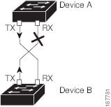
Figure 2-1 shows an example of a unidirectional link condition. Device B successfully receives traffic from device A on the port. However, device A does not receive traffic from device B on the same port. UDLD detects the problem and disables the port.
Figure 2-1 Unidirectional Link
Default UDLD Configuration
Table 2-4 shows the default UDLD configuration.
|
|
|
|---|---|
For information on configuring the UDLD for the device and its port, see the “Configuring the UDLD Mode” section.
UDLD Aggressive and Nonaggressive Modes
UDLD aggressive mode is disabled by default. You can configure UDLD aggressive mode only on point-to-point links between network devices that support UDLD aggressive mode. If UDLD aggressive mode is enabled, when a port on a bidirectional link that has a UDLD neighbor relationship established stops receiving UDLD frame, UDLD tries to reestablish the connection with the neighbor. After eight failed retries, the port is disabled.
To prevent spanning tree loops, nonaggressive UDLD with the default interval of 15 seconds is fast enough to shut down a unidirectional link before a blocking port transitions to the forwarding state (with default spanning tree parameters).
When you enable the UDLD aggressive mode, the following occurs:
- One side of a link has a port stuck (both transmission and receive)
- One side of a link remains up while the other side of the link is down
In these cases, the UDLD aggressive mode disables one of the ports on the link, which prevents traffic from being discarded.
Note![]() You enable the UDLD aggressive mode globally to enable that mode on all the fiber ports. You must enable the UDLD aggressive mode on copper ports on specified interfaces.
You enable the UDLD aggressive mode globally to enable that mode on all the fiber ports. You must enable the UDLD aggressive mode on copper ports on specified interfaces.

Tip![]() When a line card upgrade is being performed during an in-service software upgrade (ISSU) and some of the ports on the line card are members of a Layer 2 port channel and are configured with UDLD aggressive mode. If one of the remote ports is shutdown, UDLD puts the corresponding port on the local device into error disabled state. This is correct behavior.
When a line card upgrade is being performed during an in-service software upgrade (ISSU) and some of the ports on the line card are members of a Layer 2 port channel and are configured with UDLD aggressive mode. If one of the remote ports is shutdown, UDLD puts the corresponding port on the local device into error disabled state. This is correct behavior.
To restore service after the ISSU has completed, run a shutdown followed by a no shutdown command on the local port.
Carrier Delay
Note![]() You can configure the carrier delay timer only on VLAN network interfaces. It does not apply for physical ethernet interfaces, port channels, and loopback interfaces. See Chapter 4, “Configuring Layer 3 Interfaces” for information on configuring VLAN network interfaces.
You can configure the carrier delay timer only on VLAN network interfaces. It does not apply for physical ethernet interfaces, port channels, and loopback interfaces. See Chapter 4, “Configuring Layer 3 Interfaces” for information on configuring VLAN network interfaces.
If a link goes down and comes back up before the carrier delay timer expires, the down state is effectively filtered, and the rest of the software on the device is not aware that a link-down event occurred. A large carrier delay timer results in fewer link-up/link-down events being detected. When you set the carrier delay time to 0, the device detects each link-up/link-down event that occurs.
In most environments, a lower carrier delay time is better than a higher one. The exact value that you choose depends on the nature of the link outages and how long you expect these linkages to last in your network. If your data links are subject to short outages (especially if those outages last less time than it takes for your IP routing to converge), you should set a long carrier delay value to prevent these short outages from causing unnecessary problems in your routing tables. However, if your outages tend to be longer, then you may want to set a shorter carrier delay time so that the outages are detected sooner, and the IP route convergence begins and ends sooner.
The default carrier-delay time is 2 seconds or 50 milliseconds.
Port-Channel Parameters
A port channel is an aggregation of physical interfaces that comprise a logical interface. You can bundle up to eight individual interfaces into a port channel to provide increased bandwidth and redundancy. Port channeling also load balances traffic across these physical interfaces. The port channel stays operational if at least one physical interface within the port channel is operational.
You can create a Layer 2 port channel by bundling compatible Layer 2 interfaces, or you can create Layer 3 port channels by bundling compatible Layer 3 interfaces. You cannot combine Layer 2 and Layer 3 interfaces in the same port channel.
Any configuration changes that you apply to the port channel are applied to each interface member of that port channel.
For information on port channels and for information on configuring port channels, see Chapter5, “Configuring Port Channels”
Port Profiles
Beginning with Cisco NX-OS Release 4.2(1) for the Cisco Nexus 7000 Series devices, you can create a port profile that contains many interface commands and apply that port profile to a range of interfaces. Each port profile can be applied only to a specific type of interface; the choices are as follows:
Note![]() When you choose Ethernet or port channel as the interface type, the port profile is in the default mode which is Layer 3. Enter the switchport command to change the port profile to Layer 2 mode.
When you choose Ethernet or port channel as the interface type, the port profile is in the default mode which is Layer 3. Enter the switchport command to change the port profile to Layer 2 mode.
You inherit the port profile when you attach the port profile to an interface or range of interfaces, When you attach, or inherit, a port profile to an interface or range of interfaces, the system applies all the commands in that port profile to the interfaces. Additionally, you can have one port profile inherit the settings from another port profile. Inheriting another port profile allows the initial port profile to assume all of the commands of the second, inherited, port profile that do not conflict with the initial port profile. Four levels of inheritance are supported. The same port profile can be inherited by any number of port profiles.
The system applies the commands inherited by the interface or range of interfaces according to the following guidelines:
- Commands that you enter under the interface mode take precedence over the port profile’s commands if there is a conflict. However, the port profile retains that command in the port profile.
- The port profile’s commands take precedence over the default commands on the interface, unless the port-profile command is explicitly overridden by the default command.
- When a range of interfaces inherits a second port profile, the commands of the initial port profile override the commands of the second port profile if there is a conflict.
- After you inherit a port profile onto an interface or range of interfaces, you can override individual configuration values by enter the new value at the interface configuration level. If you remove the individual configuration values at the interface configuration level, the interface uses the values in the port profile again.
- There are no default configurations associated with a port profile.
A subset of commands are available under the port-profile configuration mode, depending on which interface type you specify.
Note![]() You cannot use port profiles with Session Manager. See the Cisco Nexus 7000 Series NX-OS System Management Configuration Guide, Release 4.x, for information about Session Manager.
You cannot use port profiles with Session Manager. See the Cisco Nexus 7000 Series NX-OS System Management Configuration Guide, Release 4.x, for information about Session Manager.
To apply the port-profile configurations to the interfaces, you must enable the specific port profile. You can configure and inherit a port profile onto a range of interfaces prior to enabling the port profile; you would then enable that port profile for the configurations to take effect on the specified interfaces.
If you inherit one or more port profiles onto an original port profile, only the last inherited port profile must be enabled; the system assumes that the underlying port profiles are enabled.
When you remove a port profile from a range of interfaces, the system undoes the configuration from the interfaces first and then removes the port-profile link itself. Also, when you remove a port profile, the system checks the interface configuration and either skips the port-profile commands that have been overridden by directly entered interface commands or returns the command to the default value.
If you want to delete a port profile that has been inherited by other port profiles, you must remove the inheritance before you can delete the port profile.
You can also choose a subset of interfaces from which to remove a port profile from among that group of interfaces that you originally applied the profile. For example, if you configured a port profile and configured ten interfaces to inherit that port profile, you can remove the port profile from just some of the specified ten interfaces. The port profile will continue to operate on the remaining interfaces to which it is applied.
If you delete a specific configuration for a specified range of interfaces using the interface configuration mode, that configuration is also deleted from the port profile for that range of interfaces only. For example, if you have a channel group inside a port profile and you are in the interface configuration mode and you delete that port channel, the specified port channel is also deleted from the port profile as well.
Just as in the device, you can enter a configuration for an object in port profiles without that object being applied to interfaces yet. For example, you can configure a virtual routing and forward instance (VRF) without it being applied to the system. If you then delete that VRF and attendant configurations from the port profile, the system is unaffected.
After you inherit a port profile on an interface or range of interfaces and you delete a specific configuration value, that port-profile configuration will not be operative on the specified interfaces.
If you attempt to apply a port profile to the wrong type of interface, the system returns an error.
When you attempt to enable, inherit, or modify a port profile, the system creates a checkpoint. If the port-profile configuration fails, the system rolls back to the prior configuration and returns an error. A port profile is never only partially applied.
Licensing Requirements
The following table shows the licensing requirements for this feature:
Note![]() Using VDCs requires an Advanced Services license.
Using VDCs requires an Advanced Services license.
Guidelines and Limitations
Follow these guidelines and limitations for configuring the basic interface parameters:
- Fiber-optic Ethernet ports must use Cisco-supported transceivers. To verify that the ports are using Cisco-supported transceivers, use the show interface transceivers command. Interfaces with Cisco-supported transceivers are listed as functional interfaces.
- A port can be either a Layer 2 or a Layer 3 interface; it cannot be both simultaneously.
By default, each port is a Layer 3 interface.
You can change a Layer 3 interface into a Layer 2 interface by using the switchport command. You can change a Layer 2 interface into a Layer 3 interface by using the no switchport command.
–![]() To receive pause frames when you do not know how the remote port send parameter is configured, set the local port receive parameter to desired.
To receive pause frames when you do not know how the remote port send parameter is configured, set the local port receive parameter to desired.
–![]() To receive pause frames when you know that the remote port send parameter is enabled or desired, set the local port receive parameter to enabled.
To receive pause frames when you know that the remote port send parameter is enabled or desired, set the local port receive parameter to enabled.
–![]() To ignore received pause frames, set the local port receive parameter to disabled.
To ignore received pause frames, set the local port receive parameter to disabled.
–![]() To send pause frames when you do not know how the remote port receive parameter is configured, set the local port send parameter to desired.
To send pause frames when you do not know how the remote port receive parameter is configured, set the local port send parameter to desired.
–![]() To send pause frames when you know that the remote port receive parameter is enabled or desired, set the local port send parameter to enabled.
To send pause frames when you know that the remote port receive parameter is enabled or desired, set the local port send parameter to enabled.
–![]() To prevent the sending of pause frames, set the local port send parameter to disabled.
To prevent the sending of pause frames, set the local port send parameter to disabled.
- You usually configure Ethernet port speed and duplex mode parameters to auto to allow the system to negotiate the speed and duplex mode between ports. If you decide to configure the port speed and duplex modes manually for these ports, consider the following:
–![]() Before you configure the speed and duplex mode for an Ethernet or management interface, see Table 2-2 for the combinations of speeds and duplex modes that can be configured at the same time.
Before you configure the speed and duplex mode for an Ethernet or management interface, see Table 2-2 for the combinations of speeds and duplex modes that can be configured at the same time.
–![]() If you set the Ethernet port speed to auto, the device automatically sets the duplex mode to auto.
If you set the Ethernet port speed to auto, the device automatically sets the duplex mode to auto.
–![]() If you enter the no speed command, the device automatically sets both the speed and duplex parameters to auto (the no speed command produces the same results as the speed auto command).
If you enter the no speed command, the device automatically sets both the speed and duplex parameters to auto (the no speed command produces the same results as the speed auto command).
–![]() If you configure an Ethernet port speed to a value other than auto (for example, 10, 100, or 1000 Mb/s), you must configure the connecting port to match. Do not configure the connecting port to negotiate the speed.
If you configure an Ethernet port speed to a value other than auto (for example, 10, 100, or 1000 Mb/s), you must configure the connecting port to match. Do not configure the connecting port to negotiate the speed.
Note![]() The device cannot automatically negotiate the Ethernet port speed and duplex mode if the connecting port is configured to a value other than auto.
The device cannot automatically negotiate the Ethernet port speed and duplex mode if the connecting port is configured to a value other than auto.
Configuring the Basic Interface Parameters
When you configure an interface, you must specify the interface before you can configure its parameters.
The following sections explain how to specify the interface and configure each of its basic parameters:
- Specifying the Interfaces to Configure
- Configuring the Description
- Configuring the Beacon Mode
- Changing the Bandwidth-Rate Mode
- Configuring the Error-Disabled State
- Configuring the MDIX Parameter
- Configuring the Debounce Timer
- Configuring the Interface Speed and Duplex Mode
- Configuring the Flow Control
- Configuring the MTU Size
- Configuring the Bandwidth
- Configuring the Throughput Delay
- Shutting Down and Activating the Interface
- Configuring the UDLD Mode
- Configuring the Carrier Delay Timer
- Configuring Port Profiles
Specifying the Interfaces to Configure
Before you can configure the parameters for one or more interfaces of the same type, you must specify the type and the identities of the interfaces.
Table 2-5 shows the interface types and identities that you should use for specifying the Ethernet and management interfaces.
|
|
|
|---|---|
The interface range configuration mode allows you to configure multiple interfaces with the same configuration parameters. After you enter the interface range configuration mode, all command parameters you enter are attributed to all interfaces within that range until you exit out of the interface range configuration mode.
You enter a range of interfaces using dashes (-) and commas (,). Dashes separate contiguous interfaces and commas separate noncontiguous interfaces. When you enter noncontiguous interfaces, you must enter the media type for each interface.
The following example shows how to configure a contiguous interface range:
switch(config)# interface ethernet 2/29-30
switch(config-if-range)#
The following example shows how to configure a noncontiguous interface range:
switch(config)# interface ethernet 2/29, ethernet 2/33, ethernet 2/35
switch(config-if-range)#
You can specify subinterfaces in a range only when the subinterfaces are on the same port, for example, 2/29.1-2. But you cannot specify the subinterfaces in a range of ports, for example, you cannot enter 2/29.2-2/30.2. You can specify two of the subinterfaces discretely, for example, you can enter 2/29.2, 2/30.2.
SUMMARY STEPS
DETAILED STEPS
Note![]() You do not need to add a space between the interface type and identity (port or slot/port number) For example, for the Ethernet slot 4, port 5 interface, you can specify either “ethernet 4/5” or “ethernet4/5.” The management interface is either “mgmt0” or “mgmt 0.”
You do not need to add a space between the interface type and identity (port or slot/port number) For example, for the Ethernet slot 4, port 5 interface, you can specify either “ethernet 4/5” or “ethernet4/5.” The management interface is either “mgmt0” or “mgmt 0.”
When you are in the interface configuration mode, the commands that you enter configure the interface that you specified for this mode.
Configuring the Description
You can provide textual interface descriptions for the Ethernet and management interfaces. Descriptions can be a maximum of 80 case-sensitive alphanumeric characters.
SUMMARY STEPS
DETAILED STEPS
This example shows how to set the interface description to Ethernet port 24 on module 3:
Configuring the Beacon Mode
You can enable the beacon mode for an Ethernet port to flash its LED to confirm its physical location.
SUMMARY STEPS
2.![]() interface ethernet slot / port
interface ethernet slot / port
DETAILED STEPS
This example shows how to enable the beacon mode for the Ethernet port 3/1:
This example shows how to disable the beacon mode for the Ethernet port 3/1:
Changing the Bandwidth-Rate Mode
You can specify whether each 10 Gb of bandwidth on a 32-port 10-Gigabit Ethernet module is dedicated to one port or shared by four ports in the same port group.
Dedicating Bandwidth to One Port
When you dedicate the bandwidth to one port, you must first administratively shut down the four ports in the group, change the rate mode to dedicated, and then bring the dedicated port administratively up.
SUMMARY STEPS
2.![]() interface ethernet slot / port, ethernet slot/port, ethernet slot/port, ethernet slot/port
interface ethernet slot / port, ethernet slot/port, ethernet slot/port, ethernet slot/port
4.![]() interface ethernet slot/port
interface ethernet slot/port
DETAILED STEPS
This example shows how to configure the dedicated mode for Ethernet port 4/17 in the group that includes ports 4/17, 4/19, 4/21, and 4/23:
Sharing the Bandwidth Among a Port Group
You can share 10 Gb of bandwidth among a group of ports (four ports) on a 32-port 10-Gigabit Ethernet module. To share the bandwidth, you must bring the dedicated port administratively down, specify the ports that are to share the bandwidth, change the rate mode to shared, and then bring the ports administratively up.
BEFORE YOU BEGIN
SUMMARY STEPS
2.![]() interface ethernet slot / port
interface ethernet slot / port
4.![]() interface ethernet slot/port , ethernet slot/port , ethernet slot/port , ethernet slot/port
interface ethernet slot/port , ethernet slot/port , ethernet slot/port , ethernet slot/port
DETAILED STEPS
This example shows how to configure the shared mode for Ethernet port 4/17 in the group that includes ports 4/17, 4/19, 4/21, and 4/23:
Configuring the Error-Disabled State
You can view the reason an interface moves to the error-disabled state and configure automatic recovery.
Enabling the Error Disable Detection
You can enable error-disable detection in an application. As a result, when a cause is detected on an interface, the interface is placed in an error-disabled state, which is an operational state that is similar to the link-down state.
SUMMARY STEPS
2.![]() errdisable detect cause { acl-exception | all | link-flap | loopback }
errdisable detect cause { acl-exception | all | link-flap | loopback }
DETAILED STEPS
This example shows how to enable the error-disabled detection in all cases:
Enabling the Error-Disabled Recovery
You can specify the application to bring the interface out of the error-disabled state and retry coming up. It retries after 300 seconds, unless you configure the recovery timer (see the errdisable recovery interval command).
SUMMARY STEPS
2.![]() errdisable recovery cause { all | bpdguard | link-flap | psecure-violation | security-violation | storm-control | udld }
errdisable recovery cause { all | bpdguard | link-flap | psecure-violation | security-violation | storm-control | udld }
DETAILED STEPS
This example shows how to enable error-disabled recovery under all conditions:
Configuring the Error-Disabled Recovery Interval
SUMMARY STEPS
2.![]() errdisable recovery interval interval
errdisable recovery interval interval
DETAILED STEPS
This example shows how to configure the error-disabled recovery timer to set the interval for recovery to 32 seconds:
Configuring the MDIX Parameter
If you need to detect the type of connection (crossover or straight) with another copper Ethernet port, enable the medium dependent independent crossover (MDIX) parameter for the local port. By default, this parameter is enabled.
BEFORE YOU BEGIN
SUMMARY STEPS
2.![]() interface ethernet slot/port
interface ethernet slot/port
3.![]() { mdix auto } | { no mdix }
{ mdix auto } | { no mdix }
DETAILED STEPS
This example shows how to enable MDIX for Ethernet port 3/1:
This example shows how to disable MDIX for Ethernet port 3/1:
Configuring the Debounce Timer
You can enable the debounce timer for Ethernet ports by specifying a debounce time, in milliseconds (ms), or disable the timer by specifying a debounce time of 0.
You can show the debounce times for all of the Ethernet ports by using the show interface debounce command.
SUMMARY STEPS
2.![]() interface ethernet slot/port
interface ethernet slot/port
DETAILED STEPS
This example shows how to enable the debounce timer and set the debounce time to 1000 ms for the Ethernet port 3/1:
This example shows how to disable the debounce timer for the Ethernet port 3/1:
Configuring the Interface Speed and Duplex Mode
The interface speed and duplex mode are interrelated, so you should configure both of their parameters at the same time.
To see which speeds and duplex modes you can configure together for Ethernet and management interfaces, see Table 2-2.
Note![]() The interface speed that you specify can affect the duplex mode used for an interface, so you should set the speed before setting the duplex mode. If you set the speed for autonegotiation, the duplex mode is automatically set to be autonegotiated. If you specify 10- or 100-Mb/s speed, the port is automatically configured to use half-duplex mode, but you can specify full-duplex mode instead. If you specify a speed of 1000 Mb/s (1 Gb/s) or faster, full duplex is automatically used.
The interface speed that you specify can affect the duplex mode used for an interface, so you should set the speed before setting the duplex mode. If you set the speed for autonegotiation, the duplex mode is automatically set to be autonegotiated. If you specify 10- or 100-Mb/s speed, the port is automatically configured to use half-duplex mode, but you can specify full-duplex mode instead. If you specify a speed of 1000 Mb/s (1 Gb/s) or faster, full duplex is automatically used.
BEFORE YOU BEGIN
Make sure that the remote port has a speed setting that supports your changes for the local port. If you want to set the local port to use a specific speed, you must set the remote port for the same speed or set the local port to autonegotiate the speed.
SUMMARY STEPS
3.![]() speed {{ 10 | 100 | 1000 | { auto [ 10 100 [ 1000 ]]}} | { 10000 | auto }}
speed {{ 10 | 100 | 1000 | { auto [ 10 100 [ 1000 ]]}} | { 10000 | auto }}
DETAILED STEPS
This example shows how to set the speed of Ethernet port 1 on the 48-port 10/100/1000 module in slot 3 to 1000 Mb/s and full-duplex mode:
Configuring the Flow Control
For Ethernet ports that run at 1 Gb/s or faster, you can enable or disable the port’s ability to send and receive flow-control pause frames. For Ethernet ports that run slower than 1 Gb/s, you can enable or disable only the port’s ability to receive pause frames.
When enabling flow control for the local port, you either fully enable the local port to send or receive frames regardless of the flow-control setting of the remote port, or you set the local port to use the desired setting used by the remote port. If you enable both the local and remote port for flow control, or set the desired flow control of the other port, or set a combination of those two states, flow control is enabled for those ports.
Note![]() For ports that run at 10 Gb/s, you cannot use the desired state for the send or receive parameter.
For ports that run at 10 Gb/s, you cannot use the desired state for the send or receive parameter.
BEFORE YOU BEGIN
Make sure that the remote port has the corresponding setting for the flow control that you need. If you want the local port to send flow-control pause frames, make sure that the remote port has a receive parameter set to on or desired. If you want the local port to receive flow-control frames, make sure that the remote port has a send parameter set to on or desired. If you do not want to use flow control, you can set the remote port’s send and receive parameters to off.
SUMMARY STEPS
2.![]() interface ethernet slot/port
interface ethernet slot/port
3.![]() flowcontrol { send | receive } { desired | on | off }
flowcontrol { send | receive } { desired | on | off }
DETAILED STEPS
This example shows how to set Ethernet port 3/1 to send flow control pause frames:
Configuring the MTU Size
You can configure the maximum transmission unit (MTU) size for Layer 2 and Layer 3 Ethernet interfaces. For Layer 3 interfaces, you can configure the MTU to be between 576 and 9216 bytes (even values are required). For Layer 2 interfaces, you can configure the MTU to be either the system default MTU (1500 bytes) or the system jumbo MTU size (which has the default size of 9216 bytes).
Note![]() You can change the system jumbo MTU size, but if you change that value, you should also update the Layer 2 interfaces that use that value so that they use the new system jumbo MTU value. If you do not update the MTU value for Layer 2 interfaces, those interfaces will use the system default MTU (1500 bytes).
You can change the system jumbo MTU size, but if you change that value, you should also update the Layer 2 interfaces that use that value so that they use the new system jumbo MTU value. If you do not update the MTU value for Layer 2 interfaces, those interfaces will use the system default MTU (1500 bytes).
By default, Cisco NX-OS configures Layer 3 parameters. If you want to configure Layer 2 parameters, you need to switch the port mode to Layer 2.You can change the port mode by using the switchport command.
After changing the port mode to Layer 2, you can return to configuring Layer 3 interfaces by changing the port mode again, by using the no switchport command.
Configuring the Interface MTU Size
For Layer 3 interfaces, you can configure an MTU size that is between 576 and 9216 bytes.
For Layer 2 interfaces, you can configure all Layer 2 interfaces to use either the default MTU size (1500 bytes) or the system jumbo MTU size (default size of 9216 bytes).
If you need to use a different system jumbo MTU size for Layer 2 interfaces, see the “Configuring the System Jumbo MTU Size” section.
SUMMARY STEPS
2.![]() interface ethernet slot / port
interface ethernet slot / port
3.![]() switchport | { no switchport }
switchport | { no switchport }
DETAILED STEPS
This example shows how to configure the Layer 2 Ethernet port 3/1 with the default MTU size (1500):
Configuring the System Jumbo MTU Size
You can configure the system jumbo MTU size, which can be used to specify the MTU size for Layer 2 interfaces. You can specify an even number between 1500 and 9216. If you do not configure the system jumbo MTU size, it defaults to 1500 bytes.
SUMMARY STEPS
DETAILED STEPS
This example shows how to configure the system jumbo MTU as 8000 bytes and how to change the MTU specification for an interface that was configured with the previous jumbo MTU size:
Configuring the Bandwidth
You can configure the bandwidth for Ethernet interfaces. The physical level uses an unchangeable bandwidth of 1 GB, but you can configure a value of 1 to 10,000,000 Kb for Level 3 protocols.
SUMMARY STEPS
2.![]() interface ethernet slot / port
interface ethernet slot / port
DETAILED STEPS
This example shows how to configure an informational value of 1,000,000 Kb for the Ethernet slot 3, port 1 interface bandwidth parameter:
Configuring the Throughput Delay
You can configure the interface throughput delay for Ethernet interfaces. The actual delay time does not change, but you can set an informational value between 1 and 16777215, where the value represents the number of tens of microseconds.
SUMMARY STEPS
2.![]() interface ethernet slot / port
interface ethernet slot / port
DETAILED STEPS
This example shows how to configure the throughput-delay time so that one interface is preferred over another. A lower delay value is preferred over a higher value. In this example, Ethernet 7/48 is preferred over 7/47. The default delay for 7/48 is less than the configured value on 7/47, which is set for the highest value (16777215):
Note![]() You must first ensure the EIGRP feature is enabled by running the feature eigrp command.
You must first ensure the EIGRP feature is enabled by running the feature eigrp command.
Shutting Down and Activating the Interface
You can shut down and restart Ethernet or management interfaces. When you shut down interfaces, they become disabled and all monitoring displays show them as being down. This information is communicated to other network servers through all dynamic routing protocols. When the interfaces are shut down, the interface is not included in any routing updates. To activate the interface, you must restart the device.
SUMMARY STEPS
DETAILED STEPS
This example shows how to change the administrative status for Ethernet port 3/1 from disabled to enabled:
Configuring the UDLD Mode
You can configure normal or aggressive unidirectional link detection (UDLD) modes for Ethernet interfaces on devices configured to run UDLD. Before you can enable a UDLD mode for an interface, you must make sure that UDLD is already enabled on the device that includes the interface. UDLD must also be enabled on the other linked interface and its device.
Table 2-6 lists CLI details to enable and disable UDLD on different interfaces.
|
|
|
|
|---|---|---|
To use the normal UDLD mode, you must configure one of the ports for normal mode and configure the other port for the normal or aggressive mode. To use the aggressive UDLD mode, you must configure both ports for the aggressive mode.
By default, UDLD is disabled for the 48-port, 10/100/1000 Ethernet module ports but the normal UDLD mode is enabled for the 32-port, 10-Gigabit Ethernet module ports.
BEFORE YOU BEGIN
You must enable UDLD for the other linked port and its device.
SUMMARY STEPS
2.![]() feature udld
feature udld
no feature udld
5.![]() interface ethernet slot / port
interface ethernet slot / port
DETAILED STEPS
|
|
|
|
|---|---|---|
(Optional) Specifies the interval between sending UDLD messages. The range is 7 to 90 seconds, and the default is 15 seconds. |
||
(Optional) Specifies UDLD mode to be aggressive. Note For copper interfaces, you enter the interface command mode for those interfaces you want to configure for UDLD aggressive mode and issue this command in interface command model |
||
(Optional) Specifies an interface to configure, and enters interface configuration mode. |
||
(Optional) Enables UDLD on the specified copper port or disables UDLD on the specified fiber port. To enable UDLD on copper ports. the command is udld enable. To enable UDLD on fiber ports, the command is no udld disable. See Table 2-6 for more details. |
||
(Optional) Copies the running configuration to the startup configuration. |
This example shows how to enable the UDLD for the device:
This example shows how to set the UDLD message interval to 30 seconds:
This example shows how to enable the aggressive UDLD mode for fiber interfaces:
This example shows how to enable the aggressive UDLD mode for the copper interface Ethernet 3/1:
This example shows how to disable UDLD for Ethernet port 3/1:
This example shows how to disable UDLD for the device:
Configuring the Carrier Delay Timer
The carrier delay timer sets a time during which all link-down/link-up events are not detected by any of the other software on the device. When you configure a longer carrier delay time, fewer link-down/link-up events are recorded. When you configure the carrier delay time to 0, the device detects each link-down/link-up event.
Note![]() You can configure the carrier delay timer only on VLAN network interfaces; you cannot configure this timer in any other interface modes.
You can configure the carrier delay timer only on VLAN network interfaces; you cannot configure this timer in any other interface modes.
BEFORE YOU BEGIN
Ensure that you are in VLAN interface mode. You cannot configure the carrier delay timer in any other interface mode.
SUMMARY STEPS
3.![]() carrier-delay { sec | msec number }
carrier-delay { sec | msec number }
DETAILED STEPS
This example shows how to set the carrier delay timer to 20 seconds for VLAN 5:
Configuring Port Profiles
You can apply several configuration parameters to a range of interfaces simultaneously. All the interfaces in the range must be the same type. You can also inherit the configurations from one port profile into another port profile. The system supports four levels of inheritance.
Creating a Port Profile
You can create a port profile on the device. Each port profile must have a unique name across types and the network.
SUMMARY STEPS
2.![]() port-profile [ type { ethernet | interface-vlan | loopback | port channel | tunnel }] name
port-profile [ type { ethernet | interface-vlan | loopback | port channel | tunnel }] name
DETAILED STEPS
This example shows how to create a port profile named test for tunnel interfaces:
Entering Port-Profile Configuration Mode and Modifying a Port Profile
You can enter the port-profile configuration mode and modify a port profile. To modify the port profile, you must be in the port-profile configuration mode.
SUMMARY STEPS
2.![]() port-profile [ type { ethernet | interface-vlan | loopback | port channel | tunnel }] name
port-profile [ type { ethernet | interface-vlan | loopback | port channel | tunnel }] name
DETAILED STEPS
This example shows enter the port-profile configuration mode for the specified port profile and bring all the interfaces administratively up:
Assigning a Port Profile to a Range of Interfaces
You can assign a port profile to an interface or to a range of interfaces. All the interfaces must be the same type.
SUMMARY STEPS
2.![]() interface [ethernet slot/port | interface-vlan vlan-id | loopback number | port-channel number | tunnel number ]
interface [ethernet slot/port | interface-vlan vlan-id | loopback number | port-channel number | tunnel number ]
DETAILED STEPS
This example shows how to assign the port profile named adam to Ethernet interfaces 7/3 to 7/5, 10/2, and 11/20 to 11/25:
Enabling a Specific Port Profile
To apply the port-profile configurations to the interfaces, you must enable the specific port profile. You can configure and inherit a port profile onto a range of interfaces before you enable that port profile. You would then enable that port profile for the configurations to take effect on the specified interfaces.
If you inherit one or more port profiles onto an original port profile, only the last inherited port profile must be enabled; the system assumes that the underlying port profiles are enabled.
You must be in the port-profile configuration mode to enable or disable port profiles.
SUMMARY STEPS
2.![]() port-profile [ type { ethernet | interface-vlan | loopback | port channel | tunnel }] name
port-profile [ type { ethernet | interface-vlan | loopback | port channel | tunnel }] name
DETAILED STEPS
This example shows how to enter the port-profile configuration mode and enable the port profile:
Inheriting a Port Profile
You can inherit a port profile onto an existing port profile. The system supports four levels of inheritance.
SUMMARY STEPS
DETAILED STEPS
This example shows how to inherit the port profile named adam onto the port profile named test:
Removing a Port Profile from a Range of Interfaces
You can remove a port profile from some or all of the interfaces to which you have applied the profile. You do this in the interfaces configuration mode.
SUMMARY STEPS
2.![]() interface [ethernet slot/port | interface-vlan vlan-id | loopback number | port-channel number | tunnel number ]
interface [ethernet slot/port | interface-vlan vlan-id | loopback number | port-channel number | tunnel number ]
DETAILED STEPS
This example shows how to remove the port profile named adam from Ethernet interfaces 7/3 to 7/5, 10/2, and 11/20 to 11/25:
Removing an Inherited Port Profile
You can remove an inherited port profile. You do this in the port-profile mode.
SUMMARY STEPS
DETAILED STEPS
|
|
|
|
|---|---|---|
Enters the port-profile configuration mode for the specified port profile. |
||
(Optional) Copies the running configuration to the startup configuration. |
This example shows how to remove the inherited port profile named adam from the port profile named test:
Verifying the Basic Interface Parameters
You can verify the basic interface parameters by displaying their values. You can also clear the counters listed when you display the parameter values.
Note![]() The system displays only those ports that are allocated to the VDC that you are working in.
The system displays only those ports that are allocated to the VDC that you are working in.
DETAILED STEPS
To display basic interface configuration information, perform one of the following tasks:
|
|
|
|---|---|
Displays the UDLD status for the current interface or all interfaces. |
|
For detailed information about the fields in the output from these commands, see the Cisco NX-OS Interfaces Configuration Command Reference.
Displaying and Clearing the Interface Counters
You can display and clear interface counters using Cisco NX-OS. This section discusses the following topics:
Displaying Interface Statistics
You can set up to three sampling intervals for statistics collections on interfaces.
SUMMARY STEPS
DETAILED STEPS
This example shows how to set the three sample intervals for the Ethernet port 3/1:
Clearing Interface Counters
You can clear the Ethernet and management interface counters using the clear counters command. You can perform this task from the configuration mode or interface configuration mode.
SUMMARY STEPS
DETAILED STEPS
|
|
|
|
|---|---|---|
This example shows how to clear and reset the counters on Ethernet port 5/5:
Default Settings
Table 2-7 lists the default settings for the basic interface parameters.
|
|
|
|---|---|
Additional References
For additional information related to implementing Feature-1, see the following sections:
Related Documents
Standards
|
|
|
|---|---|
No new or modified standards are supported by this feature, and support for existing standards has not been modified by this feature. |
Feature History for Configuring Basic Interface Parameters
Table 2-8 lists the release history for this feature.
|
|
|
|
|---|---|---|
Allows you to apply several configurations to a range of interfaces at once. |
 Feedback