FCoE with vPC Configuration Example
Beginning with Cisco NX-OS Release 4.1(3)N1(1), the Cisco Nexus 5000 Series switch supports vPCs which can be configured to increase bandwidth and increased load-balancing to the Ethernet fabric. This appendix includes a sample configuration on how to configure FCoE when using vPCs on the Cisco Nexus 5000 Series switch and includes the following sections:
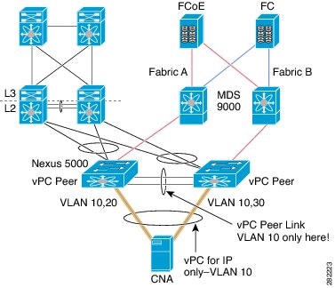
Figure 4-1 shows the topology used in the examples described in this appendix.
Figure 4-1 Nexus 5000 FCoE and vPC Lab Topology
Note FCoE VLANs should not be trunked across vPC peer-links.
The configuration example includes the following parameters:
switchname: n5k-tme-1
switchname: n5k-tme-2
mgmt ip: 172.25.182.66
mgmt ip: 172.25.182.67
The configuration example includes the following hardware:
- Dell Server PE2950
- QLogic QLE8142 (Schultz) Generation-2 CNA
- 2 Cisco Nexus 5010 switches running Cisco NX-OS Release 4.1(3)N1(1)
The configuration example includes the following considerations and requirements:
1. Generation 2 CNAs that support DCBX are required.
2. Single host CNA port channel connection to a separate switch. FCoE interfaces will not be brought up if the port channel on a single switch contains more than one member port in a port channel or vPC.
3. Cisco NX-OS Release 4.1(3)N1(1) or a later release.
4. FC Features Package (FC_FEATURES_PKG) is necessary for running FCoE. If this is not installed, there will be a temporary license that will last 90 days.
This appendix includes the following sections:
Cisco Nexus 5000 Series Switch vPC Configuration Example
This example presumes that the basic configuration has been completed on the switch (for example, IP Address (mgmt0), switchname, and password for the administrator).
This example shows how to configure the basic vPC configuration. For more information on configuring vPC, refer to the Cisco Nexus 5000 Series vPC Quick Configuration Guide.
Note The configuration must be done on both peer switches in the vPC topology.
Step 1 Enable the vPC feature on both peer switches.
Enter configuration commands, one per line. End with CNTL/Z.
tme-n5k-1(config)# feature vpc
Enter configuration commands, one per line. End with CNTL/Z.
tme-n5k-2(config)# feature vpc
Step 2 Configure the vPC domain and peer-keep alive destinations:
tme-n5k-1(config)# vpc domain 2
tme-n5k-1(config-vpc-domain)# peer-keepalive destination 192.165.200.229
tme-n5k-2(config)# vpc domain 2
tme-n5k-2(config-vpc-domain)# peer-keepalive destination 192.165.200.230
Note In this set up, switch tme-n5k-1 has the mgmt IP address of 192.165.200.229 and switch tme-n5k-2 has the mgmt IP address of 192.165.200.230.
Step 3 Configure the port channel interface that will be used as the vPC peer-link:
tme-n5k-1(config)# int port-channel 1
tme-n5k-1(config-if)# vpc peer-link
Note The spanning tree port type is changed to network port type on vPC peer-link. This will enable STP Bridge Assurance on vPC peer-link provided that the STP Bridge Assurance (which is enabled by default) is not disabled.
tme-n5k-2(config)# int port-channel 1
tme-n5k-2(config-if)# vpc peer-link
Step 4 Verify that the peer-keepalive can be reached:
tme-n5k-1(config)# show vpc peer-keepalive
vPC keep-alive status : peer is alive
--Destination : 172.25.182.167
--Receive status : Success
--Last update from peer : (0) seconds, (975) msec
tme-n5k-2(config)# show vpc peer-keepalive
--PC keep-alive status : peer is alive
--Destination : 172.25.182.166
--Receive status : Success
--Last update from peer : (0) seconds, (10336) msec
Step 5 Add member ports to the vpc-peer link port channel and bring up the port channel interface:
tme-n5k-1(config-if-range)# int po 1
tme-n5k-1(config-if)# switchport mode trunk
tme-n5k-1(config-if)# no shut
tme-n5k-1(config-if)# exit
tme-n5k-1(config)# int eth 1/39-40
tme-n5k-1(config-if-range)# switchport mode trunk
tme-n5k-1(config-if-range)# channel-group 1
tme-n5k-1(config-if-range)# no shut
tme-n5k-1(config-if-range)#
tme-n5k-2(config-if-range)# int po 1
tme-n5k-2(config-if)# switchport mode trunk
tme-n5k-2(config-if)# no shut
tme-n5k-2(config-if)# exit
tme-n5k-2(config)# int eth 1/39-40
tme-n5k-2(config-if-range)# switchport mode trunk
tme-n5k-2(config-if-range)# channel-group 1
tme-n5k-2(config-if-range)# no shut
tme-n5k-2(config-if-range)#
tme-n5k-1(config-if-range)# show int po1
Hardware: Port-Channel, address: 000d.ecde.a92f (bia 000d.ecde.a92f)
MTU 1500 bytes, BW 20000000 Kbit, DLY 10 usec,
reliability 255/255, txload 1/255, rxload 1/255
Input flow-control is off, output flow-control is off
Switchport monitor is off
Members in this channel: Eth1/39, Eth1/40
Last clearing of "show interface" counters never
1 minute input rate 1848 bits/sec, 0 packets/sec
1 minute output rate 3488 bits/sec, 3 packets/sec
tme-n5k-1(config-if-range)#
tme-n5k-2(config-if-range)# show int po1
Hardware: Port-Channel, address: 000d.ecdf.5fae (bia 000d.ecdf.5fae) MTU 1500 bytes, BW 20000000 Kbit, DLY 10 usec,
reliability 255/255, txload 1/255, rxload 1/255
Input flow-control is off, output flow-control is off
Switchport monitor is off
Members in this channel: Eth1/39, Eth1/40
Last clearing of "show interface" counters never
minute input rate 1848 bits/sec, 0 packets/sec
minute output rate 3488 bits/sec, 3 packets/sec
tme-n5k-2(config-if-range)#
Step 6 Create the vPC and add member interfaces:
tme-n5k-1(config)# int po 11
tme-n5k-1(config-if)# vpc 11
tme-n5k-1(config-if)# switchport mode trunk
tme-n5k-1(config-if)# no shut
tme-n5k-1(config-if)# int eth 1/1
tme-n5k-1(config-if)# switchport mode trunk
tme-n5k-1(config-if)# channel-group 11
tme-n5k-1(config-if)# spanning-tree port type edge trunk
Warning Edge port type (portfast) should only be enabled on ports connected to a single host. Connecting some devices such as hubs, concentrators, switches, or bridges to this interface when edge port type (portfast) is enabled, can cause temporary bridging loops. Caution should be used in this type of configuration
tme-n5k-2(config)# int po 11
tme-n5k-2(config-if)# vpc 11
tme-n5k-2(config-if)# switchport mode trunk
tme-n5k-2(config-if)# no shut
tme-n5k-2(config-if)# int eth 1/1
tme-n5k-2(config-if)# switchport mode trunk
tme-n5k-2(config-if)# channel-group 11
tme-n5k-2(config-if)# spanning-tree port type edge trunk
Warning Edge port type (portfast) should only be enabled on ports connected to a single host. Connecting some devices such as hubs, concentrators, switches, or bridges to this interface when edge port type (portfast) is enabled, can cause temporary bridging loops. Caution should be used in this type of configuration.
Note To run FCoE over a vPC topology, the port channel can only have a sinlge member interface.
Note The vPC number configured under the port channel interface must match on both Nexus 5000 switches. The port channel interface number does not have to match on both switches.
Step 7 Verify that the vPC interfaces are up and operational:
tme-n5k-1(config-if)# show vpc statistics vpc 11
vPC Status: Up, vPC number: 11
Hardware: Port-Channel, address: 000d.ecde.a908 (bia 000d.ecde.a908)
MTU 1500 bytes, BW 10000000 Kbit, DLY 10 usec,
reliability 255/255, txload 1/255, rxload 1/255
Input flow-control is off, output flow-control is off
Switchport monitor is off
Members in this channel: Eth1/1
Last clearing of "show interface" counters never
minute input rate 4968 bits/sec, 8 packets/sec
minute output rate 792 bits/sec, 1 packets/sec
tme-n5k-2(config-if)# show vpc statistics vpc 11
vPC Status: Up, vPC number: 11
Hardware: Port-Channel, address: 000d.ecdf.5fae (bia 000d.ecdf.5fae)
MTU 1500 bytes, BW 10000000 Kbit, DLY 10 usec,
reliability 255/255, txload 1/255, rxload 1/255
Input flow-control is off, output flow-control is off
Switchport monitor is off
Members in this channel: Eth1/1
Last clearing of "show interface" counters never
minute input rate 4968 bits/sec, 8 packets/sec
minute output rate 792 bits/sec, 1 packets/sec
Cisco Nexus 5000 Series Switch FCoE Configuration Example
Once the vPC is set up between the two Nexus 5000s, we can move on to configuring the FCoE topology. This cheat sheet presumes that basic configuration has been executed on the Nexus 5000 switch that will provide IP Address (mgmt0), switchname, password for admin, etc. and that the vPC configuration has been completed as outlined in the previous section. The following steps will walk through the basic FCoE configuration necessary to set up an FCoE topology in conjunction with the vPC topology.
Step 1 Enable FCoE on the Nexus 5000:
tme-n5k-1(config)# feature fcoe
FC license checked out successfully
fc_plugin extracted successfully
FC plugin loaded successfully
FCoE manager enabled successfully
FC enabled on all modules successfully
tme-n5k-2(config)# feature fcoe
FC license checked out successfully
fc_plugin extracted successfully
FC plugin loaded successfully
FCoE manager enabled successfully
FC enabled on all modules successfully
Note This can take a few moments to complete.
Step 2 Create a VSAN and map it to a VLAN that has been designated to carry FCoE traffic:
tme-n5k-1(config)# vsan database
tme-n5k-1(config-vsan-db)# vsan 100
tme-n5k-1(config-vsan-db)# exit
tme-n5k-1(config)# vlan 100
me-n5k-1(config-vlan)# fcoe vsan 100
tme-n5k-1(config-vlan)# show vlan fcoe
-------- -------- --------
tme-n5k-2(config)# vsan database
tme-n5k-2(config-vsan-db)# vsan 101
tme-n5k-2(config-vsan-db)# exit
tme-n5k-2(config)# vlan 101
tme-n5k-2(config-vlan)# fcoe vsan 101
tme-n5k-2(config-vlan)# show vlan fcoe
-------- -------- --------
Note VLAN and VSAN numbers are not required to be the same.
Step 3 Configure the VLANs that are allowed to transverse the vPC links:
tme-n5k-1(config)# int po 11
tme-n5k-1(config-if)# switchport trunk allowed vlan 1, 100
tme-n5k-1(config-if)# show int trunk
------------------------------------------------------------------
------------------------------------------------------------------
------------------------------------------------------------------
Port Vlans Allowed on Trunk
------------------------------------------------------------------
------------------------------------------------------------------
Port Vlans Err-disabled on Trunk
------------------------------------------------------------------
------------------------------------------------------------------
------------------------------------------------------------------
tme-n5k-2(config)# int po 11
tme-n5k-2(config-if)# switchport trunk allowed vlan 1, 101
tme-n5k-2(config-if)# show int trunk
------------------------------------------------------------------
------------------------------------------------------------------
------------------------------------------------------------------
Port Vlans Allowed on Trunk
------------------------------------------------------------------
------------------------------------------------------------------
Port Vlans Err-disabled on Trunk
------------------------------------------------------------------
------------------------------------------------------------------
------------------------------------------------------------------
Step 4 Create a virtual Fibre Channel interface (vfc) and add it to the VSAN that was created in the previous step:
tme-n5k-1(config)# int vfc 1
tme-n5k-1(config-if)# bind interface po11
Warning: VFC will not come up for pre-FIP CNA
tme-n5k-1(config-if)# no shut
tme-n5k-2(config)# int vfc 1
tme-n5k-2(config-if)# bind interface po11
Warning: VFC will not come up for pre-FIP CNA
tme-n5k-2(config-if)# no shut
tme-n5k-1(config)# vsan database
tme-n5k-1(config-vsan-db)# vsan 100 interface vfc 1
tme-n5k-1(config)# show vsan membership
vsan 4079(evfp_isolated_vsan) interfaces:
vsan 4094(isolated_vsan) interfaces:
tme-n5k-2(config)# vsan database
tme-n5k-2(config-vsan-db)# vsan 101 interface vfc 1
tme-n5k-2(config)# show vsan membership
vsan 4079(evfp_isolated_vsan) interfaces:
vsan 4094(isolated_vsan) interfaces:
Step 5 Verify that the vfc is up and operational:
tme-n5k-1(config-if)# show int brief
------------------------------------------------------------------
Ethernet VLAN Type Mode Status Reason Speed
------------------------------------------------------------------
Eth1/1 1 eth trunk up none 10G(D)
Eth1/2 1 eth access up none 10G(D)
Eth1/38 1 eth access down SFP not inserted 10G(D)
Eth1/39 1 eth trunk up none 10G(D)
Eth1/40 1 eth trunk up none 10G(D)
------------------------------------------------------------------
Port-channel VLAN Type Mode Status Reason Speed
------------------------------------------------------------------
Po1 1 eth trunk up none a-10G(D) none
Po11 1 eth trunk up none a-10G(D) none
------------------------------------------------------------------
Port VRF Status IP Address Speed MTU
------------------------------------------------------------------
mgmt0 -- up 172.25.182.166 1000 1500
------------------------------------------------------------------
Interface Vsan Admin Admin Status SFP Oper Oper Port
------------------------------------------------------------------
vfc1 100 F on up -- F auto --
tme-n5k-2(config-if)# show int brief
------------------------------------------------------------------
Ethernet VLAN Type Mode Status Reason Speed Port
------------------------------------------------------------------
Eth1/1 1 eth trunk up none 10G(D) 11
Eth1/2 1 eth access up none 10G(D) --
Eth1/38 1 eth access down SFP not inserted 10G(D) --
Eth1/39 1 eth trunk up none 10G(D) 1
Eth1/40 1 eth trunk up none 10G(D) 1
------------------------------------------------------------------
Port-channel VLAN Type Mode Status Reason Speed Protocol
------------------------------------------------------------------
Po1 1 eth trunk up none a-10G(D) none
Po11 1 eth trunk up none a-10G(D) none
------------------------------------------------------------------
Port VRF Status IP Address Speed MTU
------------------------------------------------------------------
mgmt0 -- up 172.25.182.167 1000 1500
------------------------------------------------------------------
Interface Vsan Admin Admin Status SFP Oper Oper
------------------------------------------------------------------
vfc1 101 F on up -- F auto --
Step 6 Verify that the virtual Fibre Channel interface has logged into the fabric:
tme-n5k-1# show flogi database
------------------------------------------------------------------
INTERFACE VSAN FCID PORT NAME NODE NAME
-----------------------------------------------------------------------
vfc1 100 0x540000 21:00:00:c0:dd:11:2a:01 20:00:00:c0:dd:11:2a:01
Total number of flogi = 1.
tme-n5k-2# show flogi database
-----------------------------------------------------------------------
INTERFACE VSAN FCID PORT NAME NODE NAME
------------------------------------------------------------------------
vfc1 101 0x540000 21:00:00:c0:dd:11:2a:01 20:00:00:c0:dd:11:2a:01
Total number of flogi = 1.
Step 7 Verify that the vPC is up and operational:
tme-n5k-1(config-if)# show vpc statistics vpc 11
vPC Status: Up, vPC number: 11
Hardware: Port-Channel, address: 000d.ecde.a908 (bia 000d.ecde.a908)
MTU 1500 bytes, BW 10000000 Kbit, DLY 10 usec,
reliability 255/255, txload 1/255, rxload 1/255
Input flow-control is off, output flow-control is off
Switchport monitor is off
Members in this channel: Eth1/1
Last clearing of "show interface" counters never
1 minute input rate 4968 bits/sec, 8 packets/sec
1 minute output rate 792 bits/sec, 1 packets/sec
tme-n5k-2(config-if)# show vpc statistics vpc 11
vPC Status: Up, vPC number: 11
Hardware: Port-Channel, address: 000d.ecdf.5fae (bia 000d.ecdf.5fae)
MTU 1500 bytes, BW 10000000 Kbit, DLY 10 usec,
reliability 255/255, txload 1/255, rxload 1/255
Input flow-control is off, output flow-control is off
Switchport monitor is off
Members in this channel: Eth1/1
Last clearing of "show interface" counters never
1 minute input rate 4968 bits/sec, 8 packets/sec
1 minute output rate 792 bits/sec, 1 packets/sec


 Feedback