Cisco Nexus 5000 Series NX-OS FCoE Operations Guide, Release 5.1(3)N1(1)
Bias-Free Language
The documentation set for this product strives to use bias-free language. For the purposes of this documentation set, bias-free is defined as language that does not imply discrimination based on age, disability, gender, racial identity, ethnic identity, sexual orientation, socioeconomic status, and intersectionality. Exceptions may be present in the documentation due to language that is hardcoded in the user interfaces of the product software, language used based on RFP documentation, or language that is used by a referenced third-party product. Learn more about how Cisco is using Inclusive Language.
- Updated:
- August 15, 2013
Chapter: FCoE with Cisco Nexus 4000 Series Switch Configuration Examples
- Cisco Nexus 5000 Series Switch in Switching Mode
- Configuring a SAN Port Channel on the Cisco Nexus 5000 Series Switch to the Cisco MDS Directory Series
- Configuring a Port Channel on a Cisco Nexus 5000 Series Switch to a Cisco Nexus 4000 Series Switch
- Configuring a Virtual Fibre Channel Interface on a Cisco Nexus 4000 Series Switch
- Configuring a VSAN on the Cisco Nexus 5000 Series Switch
- Configuring An FCoE VLAN on the Cisco Nexus 5000 Series Switch
- Configuring a FIP Snooping VLAN on the Cisco Nexus 4000 Series Switch
- Configuring the Cisco Nexus 4000 Series Switch Uplinks To Allow FCoE Traffic
- Configuring Blade Server Ethernet Interfaces on the Cisco Nexus 4000 Series Switch For FCoE Traffic
FCoE with Cisco Nexus 4000 Series Switch Configuration Example
This section includes a configuration example on how to configure an IBM blade server connecting to a Cisco Nexus 4000 Series switch which is then connected to a Cisco Nexus 5000 Series switch which accesses FC storage on a Cisco MDS 9000 Series Family switch using FCoE. Because the Cisco Nexus 4000 Series switch is a FIP snooping bridge, the FLOGI done by the CNAs do not login on the Cisco Nexus 4000 Series switch but onto the Cisco Nexus 5000 Series switch, which is the FCF. Creation of the vFC interface for the Cisco Nexus 4000 Series switch blade servers does not change whether the Cisco Nexus 5000 Series switch is in switching or NPV mode. Where the actual fabric login happens is determined by the mode on the Cisco Nexus 5000 Series switch.
- Cisco Nexus 5000 Series switch in switching mode—Login is on the Cisco Nexus 5000 Series switch.
- Cisco Nexus 5000 Series switch in NPV mode—Login will be on the Cisco MDS 9000 Series Family switch or any FC switch upstream with NPIV configured.
In this example, the Cisco Nexus 5000 Series switch in switching mode. Figure 5-1 shows the topology used in the example.
Figure 5-1 Nexus 4000 FCoE Lab Topology
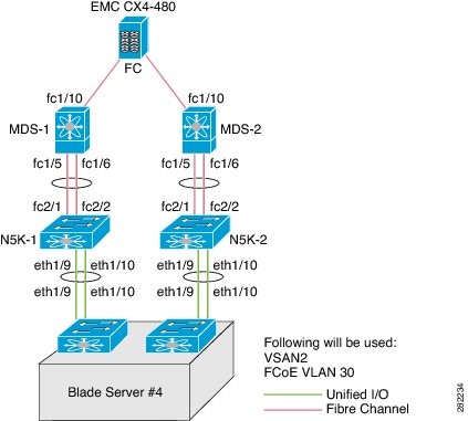
The following hardware was used:
- IBM Blade Chassis model BCH
- IBM HS22 blade server running Windows 2003 using the Qlogic QMI8142
- Cisco Nexus 4000 Series switch running Cisco NX-OS Release 4.1(2)E1(1)
- Cisco Nexus 5010 switch running Cisco NX-OS Release 4.1(3)N1(1)
- Cisco MDS 9124 Director switch running Cisco SAN-OS Release 4.1(3a)
- EMC CX4-480
This appendix includes the following sections:
- Cisco Nexus 5000 Series Switch in Switching Mode
- Configuring a SAN Port Channel on the Cisco Nexus 5000 Series Switch to the Cisco MDS Directory Series
- Configuring a Port Channel on a Cisco Nexus 5000 Series Switch to a Cisco Nexus 4000 Series Switch
- Configuring a Virtual Fibre Channel Interface on a Cisco Nexus 4000 Series Switch
- Configuring a VSAN on the Cisco Nexus 5000 Series Switch
Cisco Nexus 5000 Series Switch in Switching Mode
Before following the steps in this example, be sure to complete a basic configuration on the Cisco Nexus 5000 Series switch (for example, IP Address (mgmt0), switch name, and password for the administrator) and FCoE has not been enabled.
To use this configuration example in production, you must have the FC Features Package license installed otherwise there will be a temporary license that expires after 90 days. When the license expires, the feature is disabled.
On the Cisco Nexus 5000 Series switch, by default FCoE is not enabled.
This example shows how to enable FCoE:

Note![]() There are no FC interfaces, even though there is a 4x4 GEM card installed in the Cisco Nexus 5010 switch.
There are no FC interfaces, even though there is a 4x4 GEM card installed in the Cisco Nexus 5010 switch.
Note![]() Beginning with Cisco NX-OS Release 4.1(3)N1(1), the switch does not need to be reboot when you enable FCoE. The Cisco Nexus 5000 Series switch is in switching mode by default when FCoE is enabled.
Beginning with Cisco NX-OS Release 4.1(3)N1(1), the switch does not need to be reboot when you enable FCoE. The Cisco Nexus 5000 Series switch is in switching mode by default when FCoE is enabled.
Note![]() Use the show interface brief command to show the FC interfaces.
Use the show interface brief command to show the FC interfaces.
Configuring a SAN Port Channel on the Cisco Nexus 5000 Series Switch to the Cisco MDS Directory Series
This example shows how to configure a SAN port channel on the Cisco Nexus 5000 Series switch that is connected to a Cisco MDS 9000 Director. For redundancy, Cisco recommends that you create a SAN port channel from the FC interfaces.
Step 1![]() Configure a SAN port channel on the Cisco Nexus 5000 Series switch.
Configure a SAN port channel on the Cisco Nexus 5000 Series switch.
Note![]() After you add fc2/1 fc2/2 to san-port-channel 1 you need to disable the port channel. This must also be done on the switch at the other end of the port channel. Then, shut the interfaces at both ends to bring them up.
After you add fc2/1 fc2/2 to san-port-channel 1 you need to disable the port channel. This must also be done on the switch at the other end of the port channel. Then, shut the interfaces at both ends to bring them up.
Note![]() The SAN port channel is currently down because the Cisco MDS 9000 Series Director has not been configured.
The SAN port channel is currently down because the Cisco MDS 9000 Series Director has not been configured.
Step 2![]() Configure the Cisco MDS 9124 switch to create a port channel between the Cisco Nexus 5000 Series switch and the Cisco MDS 9124 switch.
Configure the Cisco MDS 9124 switch to create a port channel between the Cisco Nexus 5000 Series switch and the Cisco MDS 9124 switch.
Note![]() With the SAN port channel on the Cisco Nexus 5000 configured to the MDS, you will need to perform the same configuration on the Cisco MDS 9000 Series switch. A SAN port channel configuration on the Cisco MDS 9000 Series switch is called a port channel.
With the SAN port channel on the Cisco Nexus 5000 configured to the MDS, you will need to perform the same configuration on the Cisco MDS 9000 Series switch. A SAN port channel configuration on the Cisco MDS 9000 Series switch is called a port channel.
Note![]() After you add fc1/5 fc1/6 to port-channel 1 you need to disable the port channel. This must also be done on the switch at the other end of the port channel. Then, shut the interfaces at both ends to bring them up.
After you add fc1/5 fc1/6 to port-channel 1 you need to disable the port channel. This must also be done on the switch at the other end of the port channel. Then, shut the interfaces at both ends to bring them up.
Step 3![]() Verify that the SAN port channel on the Cisco Nexus 5000 Series switch is up and running. Use the show san-port-channel database command to show the SAN port channel configuration.
Verify that the SAN port channel on the Cisco Nexus 5000 Series switch is up and running. Use the show san-port-channel database command to show the SAN port channel configuration.
Configuring a Port Channel on a Cisco Nexus 5000 Series Switch to a Cisco Nexus 4000 Series Switch
This example shows how to configure a port channel on the Cisco Nexus 5000 Series switch that is connected to the Cisco Nexus 4000 Series switch.
Step 1![]() Configure the port channel on the Cisco Nexus 5000 Series switch.
Configure the port channel on the Cisco Nexus 5000 Series switch.
The port channel is configured to provide redundancy for traffic coming from the Cisco Nexus 4000 Series switch to the Cisco Nexus 5000 Series switch. In this example, all VLANs can traverse the port channel. The FCoE VLAN and the native VLAN must be allowed to traverse the port channel.In production environments, Network Administrators may designate other VLANs to traverse this network.
Step 2![]() Configure the port channel on the Cisco Nexus 4000 Series switch.
Configure the port channel on the Cisco Nexus 4000 Series switch.
Configuring a Virtual Fibre Channel Interface on a Cisco Nexus 4000 Series Switch
This example shows how to configure a vFC interface on a Cisco Nexus 4000 Series switch.
Step 1![]() On the Cisco Nexus 5000 Series switch, configure a VSAN to match the production VSAN on the Cisco MDS 9000 Series switch. This is a one-time configuration.
On the Cisco Nexus 5000 Series switch, configure a VSAN to match the production VSAN on the Cisco MDS 9000 Series switch. This is a one-time configuration.
Step 2![]() On the Cisco Nexus 5000 Series switch, configure an FCoE VLAN to map to the VSAN (VLAN-to-VSAN mapping). This is one-time configuration.
On the Cisco Nexus 5000 Series switch, configure an FCoE VLAN to map to the VSAN (VLAN-to-VSAN mapping). This is one-time configuration.
Step 3![]() On the Cisco Nexus 4000 Series switch, configure a FIP snooping VLAN that matches the FCoE VLAN on the Nexus 5000 Series switch. This is a one-time configuration.
On the Cisco Nexus 4000 Series switch, configure a FIP snooping VLAN that matches the FCoE VLAN on the Nexus 5000 Series switch. This is a one-time configuration.
Step 4![]() On the Cisco Nexus 4000 Series switch, configure the uplinks to allow FCoE traffic (FIP snooping).
On the Cisco Nexus 4000 Series switch, configure the uplinks to allow FCoE traffic (FIP snooping).
Step 5![]() On the Cisco Nexus 4000 Series switch blade server, configure the Ethernet interfaces for FCoE traffic.
On the Cisco Nexus 4000 Series switch blade server, configure the Ethernet interfaces for FCoE traffic.
Step 6![]() On the Cisco Nexus 5000 Series switch, configure the vFCs.
On the Cisco Nexus 5000 Series switch, configure the vFCs.
Step 7![]() On the Cisco Nexus 4000 Series switch blade server, bind the vFC to the MAC address of the blade server.
On the Cisco Nexus 4000 Series switch blade server, bind the vFC to the MAC address of the blade server.
Step 8![]() Verify that the vFC is in the correct VSAN.
Verify that the vFC is in the correct VSAN.
Note![]() Completing the above tasks ensure that the connection to an FCoE CNA on the blade server from the Nexus 4000 is successful.
Completing the above tasks ensure that the connection to an FCoE CNA on the blade server from the Nexus 4000 is successful.
Configuring a VSAN on the Cisco Nexus 5000 Series Switch
You can configure a VSAN on the Cisco Nexus 5000 Series switch using Fabric Manager, Device Manager, or the CLI. This example shows CLI configuration tasks and Fabric Manager or Device Manager GUI tasks.
This example shows the storage on the Cisco MDS 9000 Series resides on VSAN 2. Configure the VSAN to ensure that the vFCs configured on the Cisco Nexus 5000 Series switch can communicate with the storage device.
Configuring An FCoE VLAN on the Cisco Nexus 5000 Series Switch
You can configure a VLAN and then map the VLAN to a particular VSAN using the CLI. Fabric Manager and Device Manager can not be used for this configuration. Cisco recommends that you configure a separate VLAN for FCoE traffic and separate VLANs for standard Ethernet traffic.
This example shows how to create the FCoE VLAN:
Configuring a FIP Snooping VLAN on the Cisco Nexus 4000 Series Switch
On the Cisco Nexus 4000 Series switch, by default the FIP snooping feature is disabled. Cisco recommends that during the basic configuration, when prompted, you should enable FCoE and FIP snooping and configure, for example, the appropriate Class of Service (CoS) no drop, MTU, and QoS, without having to manually configure these features after the initial configuration.
The example shows how to verify that FIP snooping is enabled:
With the FCoE VLAN configured on the Cisco Nexus 5000 Series switch as VLAN 30, then the same VLAN number must be used to create the VLAN on the Cisco Nexus 4000 Series switch and the VLAN must be configured as a FIP snooping VLAN.
This example shows how to configure the VLAN on the Cisco Nexus 4000 Series switch:
Configuring the Cisco Nexus 4000 Series Switch Uplinks To Allow FCoE Traffic
In this example, we have already created the port channel that allows all VLANs to traverse the uplink between the Cisco Nexus 4000 Series switch and the Cisco Nexus 5000 Series switch from the previous section. The uplink (in this case a port channel) must be enabled to do FIP snooping with a port type mode of fcf.
This example shows how to configure the uplink:
Configuring Blade Server Ethernet Interfaces on the Cisco Nexus 4000 Series Switch For FCoE Traffic
You can configure the blade server using the CLI. Fabric Manager and Device Manager can not be used for this configuration.
Ensure that the FCoE VLAN (VLAN 30) can traverse the Ethernet interface on the blade server (Ethernet 1/4). In most cases, the CNA ports allow for both regular Ethernet traffic and FCoE traffic that resides on different VLANs. By default, all Ethernet interfaces on the Cisco Nexus 4000 Series switch is in access mode and resides on VLAN 1.
This example shows how to configure the Ethernet interface to allow multiple VLANs (trunk):
Note![]() The above command is not needed but if you want to specify the allowed VLANs, make sure the FCoE VLAN is on the allowed list as shown in the example.
The above command is not needed but if you want to specify the allowed VLANs, make sure the FCoE VLAN is on the allowed list as shown in the example.
When the trunk configuration is complete, create the vFC interface on the Cisco Nexus 5000 Series switch. You can use Device Manager or the CLI to configure the vFC interface.
Because the CNA is connected on Ethernet interface eth1/4 on the Cisco Nexus 4000 Series switch and is not physically connected to the Cisco Nexus 5000 Series switch, you must bind the vFC to the MAC address of the CNA that is doing FCoE. At this time, Qlogic is the only vendor that does FCoE on the blade server that is interoperable with the Cisco Nexus 4000 Series switch. Qlogic provides 2 separate MAC addresses, one for the standard Ethernet traffic and another specifically for FCoE.
This example shows how to identify the MAC address from the specific blade server in the IBM blade chassis.
Use the MAC address that has been identified on the blade server to create the vFC for this blade server on the Cisco Nexus 5000 series switch.
This example shows that the vFC is moved into VSAN 2. As a best practice in creating the vFC number to devices on the Cisco Nexus 4000 Series switch, you should create a numbering scheme that can easily identify where the vFCs are mapped to which blade server on which blade chassis. For this example, we are using the blade server in slot 4 on the first IBM blade chassis, which we have named BCH1. In this example, the vFC for this blade server is interface vfc104.
Bound MAC is 00:c0:dd:04:0c:df FCF priority is 128 Hardware is Virtual Fibre Channel Port WWN is 20:67:00:0d:ec:b2:b9:bf Admin port mode is F, trunk mode is on snmp link state traps are enabled Port mode is F, FCID is 0xcd0000 Port vsan is 2 [snip]
Configuring The vFC Interface Using Device Manager
This example shows how to use Device Manager to create the vFC interface.
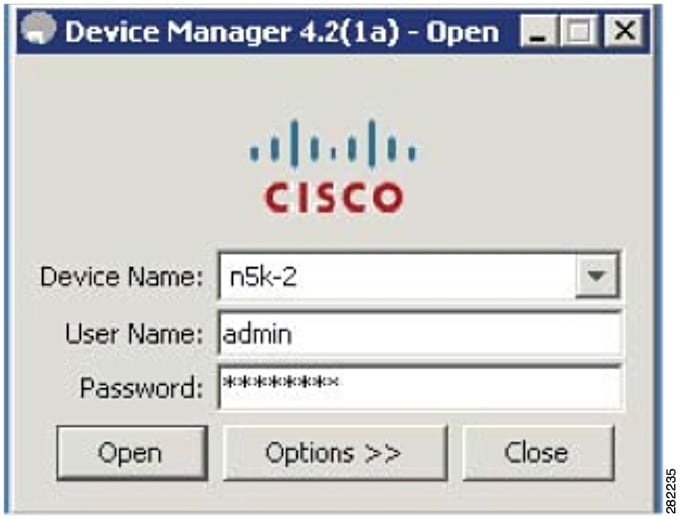
Step 1![]() Open Device Manager and login to the Cisco Nexus 5000 Series switch.
Open Device Manager and login to the Cisco Nexus 5000 Series switch.
Figure 5-2 Device Manager Login Window
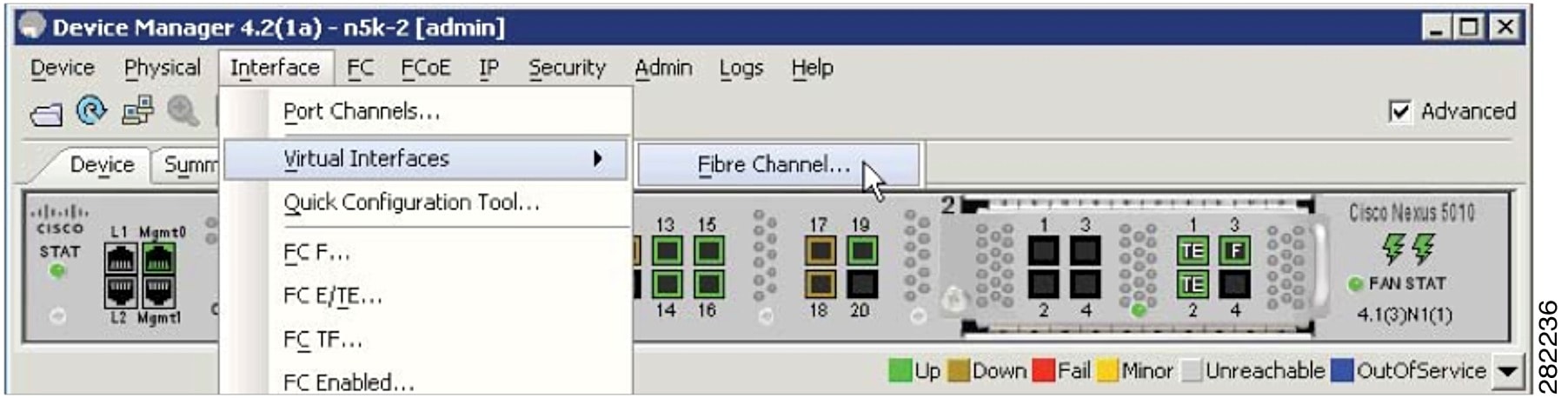
Step 2![]() From the Device Manager menu, choose Interface > Virtual Interfaces > Fibre Channel to configure one vFC. You can also use the Quick Configuration Tool to configure multiple vFCs and bind them to physical interfaces at one time.
From the Device Manager menu, choose Interface > Virtual Interfaces > Fibre Channel to configure one vFC. You can also use the Quick Configuration Tool to configure multiple vFCs and bind them to physical interfaces at one time.
Figure 5-3 Device Manager Menu
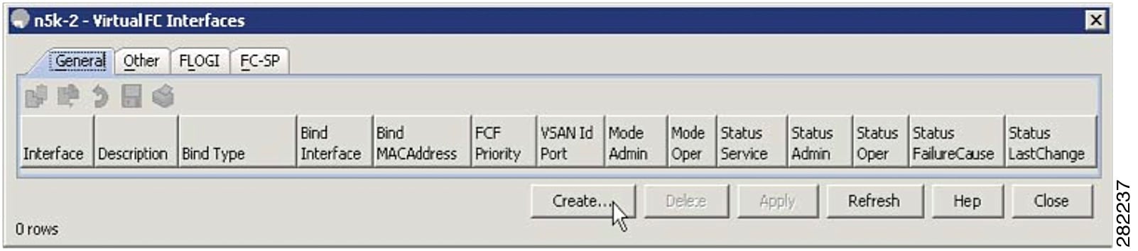
Step 3![]() From the Virtual FC Interfaces window, click Create to create the vFC.
From the Virtual FC Interfaces window, click Create to create the vFC.
Figure 5-4 Virtual FC Interfaces Window
Step 4![]() In the Create Virtual FC Interfaces General window, enter the VFC Id, Bind Type and the interface (physical or MAC address depending on the bind type) and click Create. The window is redisplayed showing the vFCs with the new vFC ID.
In the Create Virtual FC Interfaces General window, enter the VFC Id, Bind Type and the interface (physical or MAC address depending on the bind type) and click Create. The window is redisplayed showing the vFCs with the new vFC ID.
Figure 5-5 Create Virtual FC Interfaces General Window
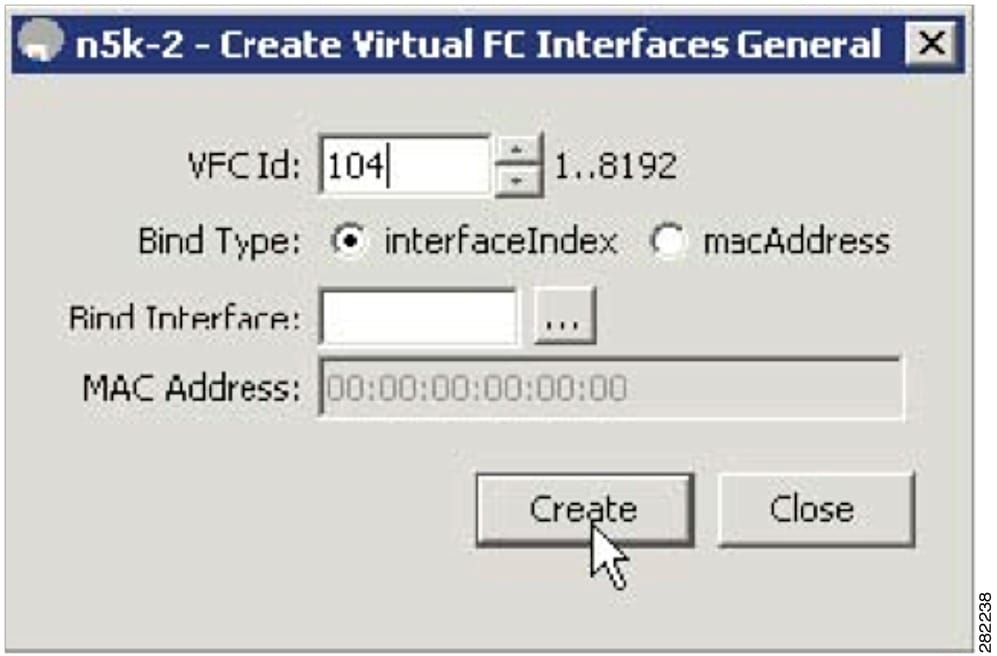
Note![]() As a best practice, create a vFC that is recognizable of the vFC back to the blade server. For example, 104 correlates to BCH1 on blade server 4.
As a best practice, create a vFC that is recognizable of the vFC back to the blade server. For example, 104 correlates to BCH1 on blade server 4.
Step 5![]() From the Virtual FC Interfaces window, choose Bind Type > macAddress.
From the Virtual FC Interfaces window, choose Bind Type > macAddress.
Figure 5-6 Changing The Bind Type From Interface to Mac Address
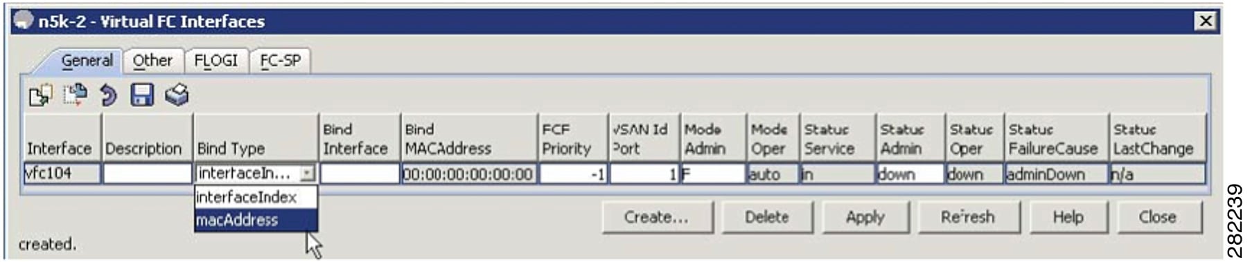
Once the Bind Type is set to macAddress, you can enter the MAC address for the blade server in the Bind MAC Address column. In this example, 00:c0:dd:04:0c:df is the MAC address. By default, the VSAN membership is set down and VSAN 1. You can edit these sections for example, VSAN 2 and up).
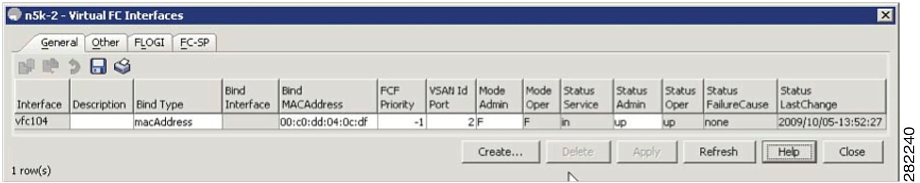
Step 6![]() Click on Apply to commit the changes and then click Refresh to validate the vFC is up.
Click on Apply to commit the changes and then click Refresh to validate the vFC is up.
Figure 5-7 The Configured vFC MAC Address in Device Manager
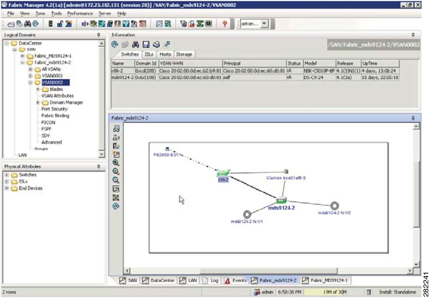
This completes the configuration of FCoE on the Cisco Nexus 4000 Series switch uplinked to the Cisco Nexus 5000 Series switch. The fabric management, for example, zoning and LUN masking, is managed with the existing SAN administrators tools. The vFC appear in Fabric Manager as a normal FC device but instead of a solid line to the host, a dash line is shown from the Cisco Nexus 5000 Series switch to the host.
Figure 5-8 Fabric Manager View With FCoE Devices
 Feedback