Technical Specifications
This appendix describes the technical specifications for the Nexus 7000 system and includes these sections:
Environmental Specifications for the Cisco Nexus 7000 Series Systems
Table A-1 lists the environmental specifications for the Cisco Nexus 7000 Series systems.
Table A-1 Environmental Specifications for the Cisco Nexus 7000 Series Switches
|
|
|
|
|
|
|
| Temperature |
Ambient operating |
32 to 104ºF (0 to 40ºC) |
| Ambient nonoperating |
–40 to 158ºF (–40 to 70ºC) |
| Relative humidity |
Ambient (noncondensing) operating |
5 to 90% (45 to 50% recommended) |
| Ambient (noncondensing) nonoperating and storage |
5 to 95% |
| Altitude |
Operating |
–500 to 13,000 feet (–150 to 4,000 meters) |
| Storage |
–1,000 to 30,000 feet (–305 to 9,144 meters) |
| Noise |
Sound pressure levels |
|
|
|
|
|
Without air filter |
70 dBA |
63.6 dBA |
67.2 dBA |
65.0 dBA |
|
With air filter |
— |
— |
70.2 dBA |
— |
| Sound power levels |
|
|
|
|
|
Without air filter |
83 dBA |
72.5 dBA |
78.9 dBA |
74.2 dBA |
|
With air filter |
— |
— |
81.7 dBA |
— |
Physical Specifications for the Cisco Nexus 7000 Series Chassis
The physical specifications differ for the Cisco Nexus 7000 Series chassis depending on the model that you are installing and the type of installation you are doing (you can front mount all models but you can optionally do a center mount of the Cisco Nexus 7004 and 7009 chassis). Table A-2 lists the physical specifications for each model and installation type.
Table A-2 Physical Specifications for Cisco Nexus 7000 Series Chassis
|
|
|
|
|
|
Cisco Nexus 7004 (all mounts) |
17.3 inches (43.9 cm) |
7 inches (17.8 cm) |
24.0 inches (61.0 cm) |
12.25 inches (31.1 cm) (7 RU) |
Cisco Nexus 7009
(front mount) |
17.3 inches (43.9 cm) |
7 inches (17.8 cm) |
24.0 inches (61.0 cm) |
24.5 inches (62.2 cm) (14 RU) |
Cisco Nexus 7009
(center mount) |
17.3 inches (43.9 cm) |
13 inches (33.0 cm) |
18.0 inches (45.8 cm) |
24.5 inches (62.2 cm) (14 RU) |
Cisco Nexus 7010
(all mounts) |
17.3 inches (43.9 cm) |
7 inches (17.8 cm) |
33.1 inches (84.1 cm) |
36.75 inches (93.3 cm) (21.0 RU) |
Cisco Nexus 7018
(all mounts |
17.3 inches (43.9 cm) |
7 inches (17.8 cm) |
33.1 inches (84.1 cm) |
43.75 inches (111.1 cm) (25.0 RU) |
The weights and quantities are listed in the following tables:
The weights in these tables do not include the rack or cabinet that holds the chassis or the interface and power cables. For those weights, see the documentation provided by the manufacturers of those components.
Table A-3 Weights and Quantities for the Cisco Nexus 7004 Switch Components
|
|
|
|
| Chassis |
45.0 lb (20.0 kg) |
1 |
| Supervisor modules |
— |
1 or 2
(must be same model) |
|
Supervisor 2 (N7K-SUP2) |
10.4 lb (4.7 kg) |
|
Supervisor 2 Enhanced (N7K-SUP2E) |
11.7 lb (5.3 kg) |
| F2 I/O Modules |
— |
1 or 2
(can mix I/O module types) |
|
48-port 1- and 10-Gigabit Ethernet I/O module (N7K-F248XP-25 and N7K-F248XP-25E) |
14.0 lb (6.4 kg) |
|
48-port 1- and 10-GBASE-T I/O module (N7K-F248XT-25E) |
14.0 lb (6.4 kg) |
| F3 I/O Modules |
— |
|
48-port 1- and 10-Gigabit Ethernet I/O module (N7K-F348XP-25) |
15.0 lb (6.8 kg) |
|
12-port, 40-Gigabit Ethernet I/O module (N7K-F312FQ-25) |
15.0 lb (6.8 kg) |
|
6-port, 100-Gigabit Ethernet I/O module (N7K-F306CK-25) |
16.0 lb (7.3 kg) |
| M1 I/O Modules |
— |
|
48-port 10/100/1000 Ethernet I/O module (N7K-M148GT-11L) |
14 lb (6.4 kg) |
|
48-port 1-Gigabit Ethernet I/O module with XL option (N7K-M148GS-11L) |
15.5 lb (7.0 kg) |
|
32-port 10-Gigabit Ethernet I/O module with XL option (N7K-M132XP-12L) |
17.0 lb (7.7 kg) |
|
8-port 10-Gigabit Ethernet I/O module with XL option (N7K-M108X2-12L) |
14.0 lb (6.4 kg) |
| M2 I/O Modules |
— |
|
24-port 10-Gigabit Ethernet I/O module with XL option (N7K-M224XP-23L) |
16.5 lb (7.5 kg) |
|
6-port 40-Gigabit Ethernet I/O module with XL option (N7K-M206FQ-23L) |
16.5 lb (7.5 kg) |
|
2-port 100-Gigabit Ethernet I/O module with XL option (N7K-M202CF-22L) |
17.0 lb (7.7 kg) |
| M3 I/O Modules |
— |
|
48-port 1- and 10-Gigabit Ethernet I/O module with XL option (N7K-M348XP-25L) |
12 lb (5.44 kg) |
|
24-port 40-Gigabit Ethernet I/O module with XL option (N7K-M324FQ-25L) |
12 lb (5.44 kg) |
| Service Modules |
— |
0 or 1 |
|
NAM (N7K-SM-NAM-K9) |
17.9 lbs. (8.1 kg) |
| Fan tray (N7K-C7004-FAN) |
25.0 lb (11.3 kg) |
1 |
| Power Supplies |
— |
1 to 4
(can mix power supply types) |
|
3-kW AC power supply (N7K-AC-3KW) |
11.0 lb (5.0 kg) |
|
3-kW DC power supply (N7K-DC-3KW) |
11.0 lb (5.0 kg) |
|
3.5-kW HVAC/HVDC power supply (N7K-HV-3.5KW |
11.0 lb (5.0 kg) |
| Optional Components |
— |
— |
|
Front door kit (N7K-C7004-FD-MB) |
— |
0 or 1 |
|
Air filter (N7K-C7004-AFLT) |
— |
0 or 1 |
Table A-4 Weights and Quantities for the Cisco Nexus 7009 Switch Components
|
|
|
|
| Chassis |
100 lb (45.0 kg) |
1 |
| Supervisor modules |
— |
1 or 2
(same type if using 2) |
|
Supervisor 1 (N7K-SUP1) |
9.9 lb (4.5 kg) |
|
Supervisor 2 (N7K-SUP2) |
10.4 lb (4.7 kg) |
|
Supervisor 2 Enhanced (N7K-SUP2E) |
11.7 lb (5.3 kg) |
| F1 I/O Modules |
— |
1 to 7
(can mix I/O module types) |
|
32-port 1- and 10-Gigabit Ethernet I/O module (N7K-F132XP-15) |
14.0 lb (6.4 kg) |
| F2 I/O Modules |
— |
|
48-port 1- and 10-Gigabit Ethernet I/O module (N7K-F248XP-25 and N7K-F248XP-25E) |
14.0 lb (6.4 kg) |
|
48-port 1- and 10-GBASE-T I/O module (N7K-F248XT-25E) |
14.0 lb (6.4 kg) |
| F3 I/O Modules |
— |
|
48-port 1- and 10-Gigabit Ethernet I/O module (N7K-F348XP-25) |
15.0 lb (6.8 kg) |
|
12-port, 40-Gigabit Ethernet I/O module (N7K-F312FQ-25) |
15.0 lb (6.8 kg) |
|
6-port, 100-Gigabit Ethernet I/O module (N7K-F306CK-25) |
16.0 lb (7.3 kg) |
| M1 I/O Modules |
— |
|
48-port 10/100/1000 Ethernet I/O module (N7K-M148GT-11) |
14 lb (6.4 kg) |
|
48-port 10/100/1000 Ethernet I/O module (N7K-M148GT-11L) |
14 lb (6.4 kg) |
|
48-port 1-Gigabit Ethernet I/O module (N7K-M148GS-11) |
15.5 lb (7.0 kg) |
|
48-port 1-Gigabit Ethernet I/O module with XL option (N7K-M148GS-11L) |
15.5 lb (7.0 kg) |
|
32-port 10-Gigabit Ethernet I/O module (N7K-M132XP-12) |
17.0 lb (7.7 kg) |
|
32-port 10-Gigabit Ethernet I/O module with XL option (N7K-M132XP-12L) |
17.0 lb (7.7 kg) |
|
8-port 10-Gigabit Ethernet I/O module with XL option (N7K-M108X2-12L) |
14.0 lb (6.4 kg) |
| M2 I/O Modules |
— |
|
24-port 10-Gigabit Ethernet I/O module with XL option (N7K-M224XP-23L) |
16.5 lb (7.5 kg) |
|
6-port 40-Gigabit Ethernet I/O module with XL option (N7K-M206FQ-23L) |
16.5 lb (7.5 kg) |
|
2-port 100-Gigabit Ethernet I/O module with XL option (N7K-M202CF-22L) |
17.0 lb (7.7 kg) |
| M3 I/O Modules |
— |
|
48-port 1- and 10-Gigabit Ethernet I/O module with XL option (N7K-M348XP-25L) |
12 lb (5.44 kg) |
|
24-port 40-Gigabit Ethernet I/O module with XL option (N7K-M324FQ-25L) |
12 lb (5.44 kg) |
| Service Modules |
— |
0 or 1 |
|
NAM (N7K-SM-NAM-K9) |
17.9 lbs. (8.1 kg) |
| Fabric Modules |
— |
For F2 I/O, use 5.
For F1, M1, and M2 I/O, use 3 to 5. |
|
Fabric-2 module (N7K-C7009-FAB-2) |
5 lb (2.27 kg) |
| Fan tray (N7K-C7009-FAN) |
25.0 lb (11.3 kg) |
1 |
| Power Supplies |
— |
1 or 2
(can mix power supply types) |
|
6-kW AC power supply unit (N7K-AC-6.0KW) |
18 lb (8.2 kg) |
|
7.5-kW AC power supply unit (N7K-AC-7.5KW-INT and N7K-AC-7.5KW-US) |
26 lb (11.8 kg) |
|
6-kW DC power supply unit (N7K-DC-6.0KW) |
21 lb (9.5 kg) |
|
DC Power Interface Unit |
5 lb (2.3 kg) |
0 to 2 |
| Optional Components |
— |
— |
|
Door and air frame (optional) |
— |
0 or 1 |
Table A-5 Weights and Quantities for the Cisco Nexus 7010 Components
|
|
|
|
| Chassis |
200 lb (90.9 kg) |
1 |
| Supervisor Modules |
— |
1 or 2
(same type if using 2) |
|
Supervisor 1 (N7K-SUP1) |
9.9 lb (4.5 kg) |
|
Supervisor 2 (N7K-SUP2) |
10.4 lb (4.7 kg) |
|
Supervisor 2 Enhanced (N7K-SUP2E) |
11.7 lb (5.3 kg) |
| F1 I/O Modules |
— |
1 to 8
(can mix I/O module types) |
|
32-port 1- and 10-Gigabit Ethernet I/O module (N7K-F132XP-15) |
14.0 lb (6.4 kg) |
| F2 I/O Modules |
— |
|
48-port 1- and 10-Gigabit Ethernet I/O module (N7K-F248XP-25 and N7K-F248XP-25E) |
14.0 lb (6.4 kg) |
|
48-port 1- and 10-GBASE-T I/O module (N7K-F248XT-25E) |
14.0 lb (6.4 kg) |
| F3 I/O Modules |
— |
|
48-port 1- and 10-Gigabit Ethernet I/O module (N7K-F348XP-25) |
15.0 lb (6.8 kg) |
|
12-port, 40-Gigabit Ethernet I/O module (N7K-F312FQ-25) |
15.0 lb (6.8 kg) |
|
6-port, 100-Gigabit Ethernet I/O module (N7K-F306CK-25) |
16.0 lb (7.3 kg) |
| M1 I/O Modules |
— |
|
48-port 10/100/1000 Ethernet I/O module (N7K-M148GT-11) |
14 lb (6.4 kg) |
|
48-port 10/100/1000 Ethernet I/O module (N7K-M148GT-11L) |
14 lb (6.4 kg) |
|
48-port 1-Gigabit Ethernet I/O module (N7K-M148GS-11) |
15.5 lb (7.0 kg) |
|
48-port 1-Gigabit Ethernet I/O module with XL option (N7K-M148GS-11L) |
15.5 lb (7.0 kg) |
|
32-port 10-Gigabit Ethernet I/O module (N7K-M132XP-12) |
17.0 lb (7.7 kg) |
|
32-port 10-Gigabit Ethernet I/O module with XL option (N7K-M132XP-12L) |
17.0 lb (7.7 kg) |
|
8-port 10-Gigabit Ethernet I/O module with XL option (N7K-M108X2-12L) |
14.0 lb (6.4 kg) |
| M2 I/O Modules |
— |
|
24-port 10-Gigabit Ethernet I/O module with XL option (N7K-M224XP-23L) |
16.5 lb (7.5 kg) |
|
6-port 40-Gigabit Ethernet I/O module with XL option (N7K-M206FQ-23L) |
16.5 lb (7.5 kg) |
|
2-port 100-Gigabit Ethernet I/O module with XL option (N7K-M202CF-22L) |
17.0 lb (7.7 kg) |
| M3 I/O Modules |
— |
|
48-port 1- and 10-Gigabit Ethernet I/O module with XL option (N7K-M348XP-25L) |
12 lb (5.44 kg) |
|
24-port 40-Gigabit Ethernet I/O module with XL option (N7K-M324FQ-25L) |
12 lb (5.44 kg) |
| Service Modules |
— |
0 or 1 |
|
NAM (N7K-SM-NAM-K9) |
17.9 lbs. (8.1 kg) |
| Fabric Modules |
— |
For F2 I/O, use 5.
For F1, M1, and M2 I/O, use 3 to 5. |
|
Fabric-1 module (N7K-C7010-FAB-1) |
4 lb (1.8 kg) |
|
Fabric-2 module (N7K-C7010-FAB-2) |
4 lb (1.8 kg) |
| Fan Trays |
— |
— |
|
System fan tray (N7K-C7010-FAN-S) |
20 lb (9.1 kg) |
2 |
|
Fabric fan tray (N7K-C7010-FAN-F) |
5 lb (2.3 kg) |
2 |
| Power Supplies |
— |
2 to 3
(can mix power supply types) |
|
6-kW AC power supply unit (N7K-AC-6.0KW) |
18 lb (8.2 kg) |
|
7.5-kW AC power supply unit (N7K-AC-7.5KW-INT and N7K-AC-7.5KW-US) |
26 lb (11.8 kg) |
|
6-kW DC power supply unit (N7K-DC-6.0KW) |
21 lb (9.5 kg) |
|
DC Power Interface Unit |
5 lb (2.3 kg) |
0 to 2 |
| Optional Components |
— |
— |
|
Mid-frame doors and frame |
— |
0 or 1 |
Table A-6 Weights and Quantities for the Cisco Nexus 7018 Components
| |
|
|
|
| Chassis |
187 lb (85.0 kg) |
1 |
| Supervisor Modules |
— |
1 or 2
(same type if using 2) |
|
Supervisor 1 (N7K-SUP1) |
9.9 lb (4.5 kg) |
|
Supervisor 2 (N7K-SUP2) |
10.4 lb (4.7 kg) |
|
Supervisor 2 Enhanced (N7K-SUP2E) |
11.7 lb (5.3 kg) |
| F1 I/O Modules |
— |
1 to 8
(can mix I/O module types) |
|
32-port 1- and 10-Gigabit Ethernet I/O module (N7K-F132XP-15) |
14.0 lb (6.4 kg) |
| F2 I/O Modules |
— |
|
48-port 1- and 10-Gigabit Ethernet I/O module (N7K-F248XP-25 and N7K-F248XP-25E) |
14.0 lb (6.4 kg) |
|
48-port 1- and 10-GBASE-T I/O module (N7K-F248XT-25E) |
14.0 lb (6.4 kg) |
| F3 I/O Modules |
— |
|
48-port 1- and 10-Gigabit Ethernet I/O module (N7K-F348XP-25) |
15.0 lb (6.8 kg) |
|
12-port, 40-Gigabit Ethernet I/O module (N7K-F312FQ-25) |
15.0 lb (6.8 kg) |
|
6-port, 100-Gigabit Ethernet I/O module (N7K-F306CK-25) |
16.0 lb (7.3 kg) |
| M1 I/O Modules |
— |
|
48-port 10/100/1000 Ethernet I/O module (N7K-M148GT-11) |
14 lb (6.4 kg) |
|
48-port 10/100/1000 Ethernet I/O module (N7K-M148GT-11L) |
14 lb (6.4 kg) |
|
48-port 1-Gigabit Ethernet I/O module (N7K-M148GS-11) |
15.5 lb (7.0 kg) |
|
48-port 1-Gigabit Ethernet I/O module with XL option (N7K-M148GS-11L) |
15.5 lb (7.0 kg) |
|
32-port 10-Gigabit Ethernet I/O module (N7K-M132XP-12) |
17.0 lb (7.7 kg) |
|
32-port 10-Gigabit Ethernet I/O module with XL option (N7K-M132XP-12L) |
17.0 lb (7.7 kg) |
|
8-port 10-Gigabit Ethernet I/O module with XL option (N7K-M108X2-12L) |
14.0 lb (6.4 kg) |
| M2 I/O Modules |
— |
|
24-port 10-Gigabit Ethernet I/O module with XL option (N7K-M224XP-23L) |
16.5 lb (7.5 kg) |
|
6-port 40-Gigabit Ethernet I/O module with XL option (N7K-M206FQ-23L) |
16.5 lb (7.5 kg) |
|
2-port 100-Gigabit Ethernet I/O module with XL option (N7K-M202CF-22L) |
17.0 lb (7.7 kg) |
| M3 I/O Modules |
— |
|
48-port 1- and 10-Gigabit Ethernet I/O module with XL option (N7K-M348XP-25L) |
12 lb (5.44 kg) |
|
24-port 40-Gigabit Ethernet I/O module with XL option (N7K-M324FQ-25L) |
12 lb (5.44 kg) |
| Service Modules |
— |
0 or 1 |
|
NAM (N7K-SM-NAM-K9) |
17.9 lbs. (8.1 kg) |
| Fabric Modules |
— |
For F2 I/O, use 5.
For F1, M1, and M2 I/O, use 3 to 5. |
|
Fabric-1 module (N7K-C7018-FAB-1) |
7.5 lb (3.4 kg) |
|
Fabric-2 module (N7K-C7018-FAB-2) |
7.5 lb (3.4 kg) |
| Fan tray (N7K-C7018-FAN) |
25.8 lb (11.7 kg) |
2 |
| Power Supplies |
— |
2 to 4
(can mix power supply types) |
|
6-kW AC power supply unit (N7K-AC-6.0KW) |
18 lb (8.2 kg) |
|
7.5-kW AC power supply unit (N7K-AC-7.5KW-INT and N7K-AC-7.5KW-US) |
26 lb (11.8 kg) |
|
6-kW DC power supply unit (N7K-DC-6.0KW) |
21 lb (9.5 kg) |
|
DC Power Interface Unit |
5 lb (2.3 kg) |
0 to 2 |
| Optional Components |
— |
— |
|
Front door (optional) |
25 lb (11.3 kg) |
0 or 1 |
Power Specifications for the Cisco Nexus 7000 Series Switches
The number of power supplies that a Cisco Nexus 7000 Series switch requires depends on the quantities and types of modules that you include in the switch chassis. the type of power supply unit that you are using, and the power redundancy mode that you are using.
The following topics explain how to calculate the switch power requirements and the amount of power available for each type of power supply configuration mode:
Power Requirements for Switch Components
To determine the power requirements of the Cisco Nexus 7000 Series switches, add the power requirements of each of its components. For each component, multiply the number of its modules by its maximum or typical power requirement. To find the quantities and power requirements for each Cisco Nexus 7000 Series switch, see the following tables:
Table A-7 Power Requirements for the Cisco Nexus 7004 Switch
|
|
|
|
|
| Supervisor Modules |
1 or 2
(same type if using 2) |
— |
— |
|
Supervisor 2 (N7K-SUP2) |
300 W |
109 W |
|
Supervisor 2 Enhanced (N7K-SUP2E) |
300 W |
147 W |
| F2 I/O Modules |
1 or 2 |
— |
— |
|
48-port 1- and 10-Gigabit Ethernet I/O module (N7K-F248XP-25 and N7K-F248XP-25E) |
450 W |
400 W |
|
48-port 1- and 10-GBASE-T I/O module (N7K-F248XT-25E) |
550 W |
420 W |
| F3 I/O Modules |
— |
— |
|
48-port 1- and 10-Gigabit Ethernet I/O module (N7K-F348XP-25) |
340 W |
325 W |
|
12-port, 40-Gigabit Ethernet I/O module (N7K-F312FQ-25) |
340 W |
310 W |
|
6-port, 100-Gigabit Ethernet I/O module (N7K-F306CK-25) |
400 W |
325 W |
| M1 I/O Modules |
— |
— |
|
48-port 10/100/1000 Ethernet I/O module with XL option (N7K-M148GT-11L) |
400 W |
358 W |
|
48-port 1-Gigabit Ethernet I/O module with XL option (N7K-M148GS-11L) |
400 W |
358 W |
|
32-port 10-Gigabit Ethernet I/O module with XL option (N7K-M132XP-12L) |
750 W |
611 W |
|
8-port 10-Gigabit Ethernet I/O module with XL option (N7K-M108X2-12L) |
650 W |
520 W |
| M2 I/O Modules |
— |
— |
|
24-port 10-Gigabit Ethernet I/O module with XL option (N7K-M224XP-23L) |
795 W |
720 W |
|
6-port 40-Gigabit Ethernet I/O module with XL option (N7K-M206FQ-23L) |
795 W |
720 W |
|
2-port 100-Gigabit Ethernet I/O module with XL option (N7K-M202CF-22L) |
795 W |
690 W |
| M3 I/O Modules |
|
— |
— |
|
48-port 1-/10-Gigabit Ethernet I/O modules with XL option(N7K-M348XP-25L) |
|
525 W |
400 W |
|
24-port 40-Gigabit Ethernet I/O modules with XL option(N7K-M324FQ-25L) |
|
750 W |
600 W |
| Fan Tray |
1 |
650 W |
185 W |
Table A-8 Power Requirements for the Cisco Nexus 7009 Switch
|
|
|
|
|
| Supervisor Modules |
1 or 2
(same type if using 2) |
— |
— |
|
Supervisor 1 (N7K-SUP1) |
210 W |
190 W |
|
Supervisor 2 (N7K-SUP2) |
300 W |
109 W |
|
Supervisor 2 Enhanced (N7K-SUP2E) |
300 W |
147 W |
| F1 I/O Modules |
1 to 7 |
— |
— |
|
32-port 1- and 10-Gigabit Ethernet I/O module (N7K-F132XP-15) |
385 W |
283 W |
| F2 I/O Modules |
— |
— |
|
48-port 1- and 10-Gigabit Ethernet I/O module (N7K-F248XP-25 and N7K-F248XP-25E) |
450 W |
400 W |
|
48-port 1- and 10-GBASE-T I/O module (N7K-F248XT-25E) |
550 W |
420 W |
| F3 I/O Modules |
— |
— |
|
48-port 1- and 10-Gigabit Ethernet I/O module (N7K-F348XP-25) |
340 W |
325 W |
|
12-port, 40-Gigabit Ethernet I/O module (N7K-F312FQ-25) |
340 W |
310 W |
|
6-port, 100-Gigabit Ethernet I/O module (N7K-F306CK-25) |
400 W |
325 W |
| M1 I/O Modules |
— |
— |
|
48-port 10/100/1000 Ethernet I/O module (N7K-M148GT-11) |
400 W |
358 W |
|
48-port 10/100/1000 Ethernet I/O module with XL option (N7K-M148GT-11L) |
400 W |
358 W |
|
48-port 1-Gigabit Ethernet I/O module (N7K-M1148GS-11) |
400 W |
358 W |
|
48-port 1-Gigabit Ethernet I/O module with XL option (N7K-M148GS-11L) |
400 W |
358 W |
|
32-port 10-Gigabit Ethernet I/O module (N7K-M132XP-12) |
750 W |
611 W |
|
32-port 10-Gigabit Ethernet I/O module with XL option (N7K-M132XP-12L) |
750 W |
611 W |
|
8-port 10-Gigabit Ethernet I/O module with XL option (N7K-M108X2-12L) |
650 W |
520 W |
| M2 I/O Modules |
— |
— |
|
24-port 10-Gigabit Ethernet I/O module with XL option (N7K-M224XP-23L) |
795 W |
720 W |
|
6-port 40-Gigabit Ethernet I/O module with XL option (N7K-M206FQ-23L) |
795 W |
720 W |
|
2-port 100-Gigabit Ethernet I/O module with XL option (N7K-M202CF-22L) |
795 W |
690 W |
| M3 I/O Modules |
|
— |
— |
|
48-port 1-/10-Gigabit Ethernet I/O modules with XL option(N7K-M348XP-25L) |
|
525 W |
400 W |
|
24-port 40-Gigabit Ethernet I/O modules with XL option(N7K-M324FQ-25L) |
|
750 W |
600 W |
| Fabric Modules |
3 to 5 |
— |
— |
|
Fabric-2 module (N7K-C7009-FAB-2) |
70 W |
55 W |
| Fan Trays |
— |
— |
— |
|
All fan trays (total) (N7K-C7009-FAN) |
650 W |
190 W |
Table A-9 Power Requirements for the Cisco Nexus 7010 System Components
|
|
|
|
|
| Supervisor Modules |
1 or 2 (same type if using 2) |
— |
— |
|
Supervisor 1 (N7K-SUP1) |
210 W |
190 W |
|
Supervisor 2 (N7K-SUP2) |
300 W |
109 W |
|
Supervisor 2 Enhanced (N7K-SUP2E) |
300 W |
147 W |
| F1 I/O Modules |
1 to 8 (can mix types) |
— |
— |
|
32-port 1- and 10-Gigabit Ethernet I/O module (N7K-F132XP-15) |
385 W |
283 W |
| F2 I/O Modules |
— |
— |
|
48-port 1- and 10-Gigabit Ethernet I/O module (N7K-F248XP-25 and N7K-F248XP-25E) |
450 W |
400 W |
|
48-port 1- and 10-GBASE-T I/O module (N7K-F248XT-25E) |
550 W |
420 W |
| F3 I/O Modules |
— |
— |
|
48-port 1- and 10-Gigabit Ethernet I/O module (N7K-F348XP-25) |
340 W |
325 W |
|
12-port, 40-Gigabit Ethernet I/O module (N7K-F312FQ-25) |
340 W |
310 W |
|
6-port, 100-Gigabit Ethernet I/O module (N7K-F306CK-25) |
400 W |
325 W |
| M1 I/O Modules |
— |
— |
|
48-port 10/100/1000 Ethernet I/O module (N7K-M148GT-11) |
400 W |
358 W |
|
48-port 10/100/1000 Ethernet I/O module with XL option (N7K-M148GT-11L) |
400 W |
358 W |
|
48-port 1-Gigabit Ethernet I/O module (N7K-M1148GS-11) |
400 W |
358 W |
|
48-port 1-Gigabit Ethernet I/O module with XL option (N7K-M148GS-11L) |
400 W |
358 W |
|
32-port 10-Gigabit Ethernet I/O module (N7K-M132XP-12) |
750 W |
611 W |
|
32-port 10-Gigabit Ethernet I/O module with XL option (N7K-M132XP-12L) |
750 W |
611 W |
|
8-port 10-Gigabit Ethernet I/O module with XL option (N7K-M108X2-12L) |
650 W |
520 W |
| M2 I/O Modules |
— |
— |
|
24-port 10-Gigabit Ethernet I/O module with XL option (N7K-M224XP-23L) |
795 W |
720 W |
|
6-port 40-Gigabit Ethernet I/O module with XL option (N7K-M206FQ-23L) |
795 W |
720 W |
|
2-port 100-Gigabit Ethernet I/O module with XL option (N7K-M202CF-22L) |
795 W |
690 W |
| M3 I/O Modules |
|
— |
— |
|
48-port 1-/10-Gigabit Ethernet I/O modules with XL option(N7K-M348XP-25L) |
|
525 W |
400 W |
|
24-port 40-Gigabit Ethernet I/O modules with XL option(N7K-M324FQ-25L) |
|
750 W |
600 W |
| Fabric Modules |
3 to 5 (same type) |
— |
— |
|
Fabric-1 module (N7K-C7010-FAB-1) |
60 W |
55 W |
|
Fabric-2 module (N7K-C7010-FAB-2) |
80 W |
60W |
| Fan Trays (N7K-C7010-FAN-F and N7K-C7010-FAN-S) |
— |
— |
— |
|
All fan trays (total) |
2184 W |
300 W |
Table A-10 Power Requirements for the Cisco Nexus 7018 System Components
|
|
|
|
|
| Supervisor Modules |
1 or 2
(same type if using 2) |
— |
— |
|
Supervisor 1 (N7K-SUP1) |
210 W |
190 W |
|
Supervisor 2 (N7K-SUP2) |
300 W |
109 W |
|
Supervisor 2 Enhanced (N7K-SUP2E) |
300 W |
147 W |
| F1 I/O Modules |
1 to 16 (can mix types) |
— |
— |
|
32-port 1- and 10-Gigabit Ethernet I/O module (N7K-F132XP-15) |
385 W |
283 W |
| F2 I/O Modules |
— |
— |
|
48-port 1- and 10-Gigabit Ethernet I/O module (N7K-F248XP-25 and N7K-F248XP-25E) |
450 W |
400 W |
|
48-port 1- and 10-GBASE-T I/O module (N7K-F248XT-25E) |
550 W |
420 W |
| F3 I/O Modules |
— |
— |
|
48-port 1- and 10-Gigabit Ethernet I/O module (N7K-F348XP-25) |
340 W |
325 W |
|
12-port, 40-Gigabit Ethernet I/O module (N7K-F312FQ-25) |
340 W |
310 W |
|
6-port, 100-Gigabit Ethernet I/O module (N7K-F306CK-25) |
400 W |
325 W |
| M1 I/O Modules |
— |
— |
|
48-port 10/100/1000 Ethernet I/O module (N7K-M148GT-11) |
400 W |
358 W |
|
48-port 10/100/1000 Ethernet I/O module with XL option (N7K-M148GT-11L) |
400 W |
358 W |
|
48-port 1-Gigabit Ethernet I/O module (N7K-M1148GS-11) |
400 W |
358 W |
|
48-port 1-Gigabit Ethernet I/O module with XL option (N7K-M148GS-11L) |
400 W |
358 W |
|
32-port 10-Gigabit Ethernet I/O module (N7K-M132XP-12) |
750 W |
611 W |
|
32-port 10-Gigabit Ethernet I/O module with XL option (N7K-M132XP-12L) |
750 W |
611 W |
|
8-port 10-Gigabit Ethernet I/O module with XL option (N7K-M108X2-12L) |
650 W |
520 W |
| M2 I/O Modules |
— |
— |
|
2-port 100-Gigabit Ethernet I/O module with XL option (N7K-M202CF-22L) |
795 W |
690 W |
|
6-port 40-Gigabit Ethernet I/O module with XL option (N7K-M206FQ-23L) |
795 W |
720 W |
|
24-port 10-Gigabit Ethernet I/O module with XL option (N7K-M224XP-23L) |
795 W |
720 W |
| M3 I/O Modules |
|
— |
— |
|
48-port 1-/10-Gigabit Ethernet I/O modules with XL option(N7K-M348XP-25L) |
|
525 W |
400 W |
|
24-port 40-Gigabit Ethernet I/O modules with XL option(N7K-M324FQ-25L) |
|
750 W |
600 W |
| Fabric Modules |
3 to 5 (same type) |
— |
— |
|
Fabric-1 module (N7K-C7018-FAB-1) |
100 W |
90 W |
|
Fabric-2 module (N7K-C7018-FAB-2) |
150 W |
110 W |
| Fan Trays (N7K-C7018-FAN) |
2 |
— |
— |
|
All fan trays (total) |
1000 W |
569 W |
Power Supply Configuration Modes
You can configure one of the following power modes to either use the combined power provided by the installed power supplies or to provide power redundancy when there is a power loss:
- Combined mode—Provides the maximum amount of available power by utilizing the combined power output from all installed power supplies for switch operations. This mode does not provide redundancy.
- Power-supply redundancy mode—Allows you to replace a power supply during switch operations. All power supplies are active. The available power is calculated as the least amount of power available from all but one of the power supplies (N+1). The reserve power is the amount of power output by the power supply that can output the most power. For example, if three power supplies output 3 kW, 6 kW, and 6 kW, the available power is 9 kW (3 kW + 6 kW) and the reserve power is 6 kW.
- Input source redundancy mode—Takes power from two electrical grids so that if one grid goes down, the other grid can provide the power needed by the switch. For the Cisco Nexus 7004 chassis, each grid powers half of the power supplies. For the Cisco Nexus 7009, 7010, and 7018 chassis, each grid powers half of each power supply (grid A is connected to the Input 1 receptacle on each power supply and grid B is connected to the Input 2 receptacle on each power supply). The available power is the amount of power output by the portions of the power supplyies that are connected to the same grid. For example, if three power supplies are connected to a 110-V grid and a 220-V grid, each power supply outputs 1.2 kW for the 110-V grid and 3.0 kW for the 220-V grid. The available power would be 3.6 kW (1.2 kW + 1.2 kW + 1.2 kW) and the reserve power would be 9.0 kW (3.0 kW + 3.0 kW + 3.0 kW).
- Full redundancy mode—Provides both power-supply redundancy and input-source redundancy. This mode allows you to replace a power supply without interrupting switch operations or continue powering the switch if one of two grids goes down. The available power is the lesser amount of output power for power supply redundancy or input source redundancy.
The amount of power available for use with your Cisco Nexus 7000 Series switch depends on the number of power supplies, input voltage used, and the power mode used. To determine the amount of available power for the power supplies, see the following tables:
Table A-11 Power Availability for 3-kW AC Power Supplies
|
|
|
Power Supply Redundancy Mode
|
Input Source Redundancy Mode
|
|
Single input per power supply |
|
|
|
|
220-V input |
|
|
|
|
1 power supply |
3000 W |
— |
— |
— |
2 power supplies |
6000 W |
3000 W |
3000 W |
3000 W |
3 power supplies |
9000 W |
6000 W |
— |
— |
4 power supplies |
12,000 W |
9000 W |
6000 W |
6000 W |
110-V input |
|
|
|
|
1 power supply |
1450 W |
— |
— |
— |
2 power supplies |
2900 W |
1450 W |
1450 W |
1450 W |
3 power supplies |
4350 W |
2900 W |
— |
— |
4 power supplies |
5800 W |
4350 W |
2900 W |
2900 W |
Table A-12 Power Availability for 3.5-kW Inputs (AC)
|
|
|
Power Supply Redundancy Mode
|
Input Source Redundancy Mode
|
|
Single input per power supply |
|
|
|
|
277-V input |
|
|
|
|
1 power supply |
3500 W |
— |
— |
— |
2 power supplies |
7000 W |
3500 W |
3500 W |
3500 W |
3 power supplies |
10,500 W |
7000 W |
— |
— |
4 power supplies |
14,000 W |
10,500 W |
7000 W |
7000 W |
220/230-V input |
|
|
|
|
1 power supply |
3500 W |
— |
— |
— |
2 power supplies |
7000 W |
3500 W |
3500 W |
3500 W |
3 power supplies |
10,500 W |
7000 W |
— |
— |
4 power supplies |
14,000 W |
10,500 W |
7000 W |
7000 W |
210-V input |
|
|
|
|
1 power supply |
3100 W |
— |
— |
— |
2 power supplies |
6200 W |
3100 W |
3100 W |
3100 W |
3 power supplies |
9300 W |
6200 W |
— |
— |
4 power supplies |
12,400 W |
9300 W |
6200 W |
6200 W |
110-V input |
|
|
|
|
1 power supply |
1500 W |
— |
— |
— |
2 power supplies |
3000 W |
1500 W |
1500 W |
1500 W |
3 power supplies |
4500 W |
3000 W |
— |
— |
4 power supplies |
6000 W |
4500 W |
3000 W |
3000 W |
Table A-13 Power Availability for 6-kW AC Power Supply Units
| |
|
Power Supply Redundancy Mode
|
Input Source Redundancy Mode
|
|
Dual inputs per power supply |
|
|
|
|
220-V and 220-V inputs |
|
|
|
|
1 power supply |
6000 W |
— |
3000 W |
— |
2 power supplies 1 |
12,000 W |
6000 W |
6000 W |
6000 W |
3 power supplies 1 |
18,000 W |
12,000 W |
9000 W |
9000 W |
4 power supplies |
24,000 W |
18,000 W |
12,000 W |
12,000 W |
220-V and 110-V inputs |
|
|
|
|
1 power supply |
4200 W |
— |
1200 W |
— |
2 power supplies 1 |
8400 W |
4200 W |
2400 W |
2400 W |
3 power supplies 1 |
12,600 W |
8400 W |
3600 W |
3600 W |
4 power supplies 1 |
16,800 W |
12,600 W |
4800 S |
4800 W |
110-V and 110-V inputs |
|
|
|
|
1 power supply |
2400 W |
— |
1200 W |
— |
2 power supplies 1 |
4800 W |
2400 W |
2400 W |
2400 W |
3 power supplies 1 |
7200 W |
4800 W |
3600 W |
3600 W |
4 power supplies 1 |
9600 W |
7200 W |
4800 W |
4800 W |
Single input per power supply |
|
|
|
|
220-V input |
|
|
|
|
1 power supply |
3000 W |
— |
— |
— |
2 power supplies 1 |
6000 W |
3000 W |
— |
— |
3 power supplies 1 |
9000 W |
6000 W |
— |
— |
4 power supplies 1 |
12,000 W |
9000 W |
— |
— |
110-V input |
|
|
|
|
1 power supply |
1200 W |
— |
— |
— |
2 power supplies 1 |
2400 W |
1200 W |
— |
— |
3 power supplies 1 |
3600 W |
2400 W |
— |
— |
4 power supplies 1 |
4800 W |
3600 W |
— |
— |
Table A-14 Power Availability for 7.5-kW AC Power Supplies
| |
|
Power
Supply
Redundancy
Mode
|
Input Source
Redundancy
Mode
|
|
Dual inputs per power supply |
|
|
|
|
220-V and 220-V inputs |
|
|
|
|
1 power supply |
7500 W |
— |
3750 W |
— |
2 power supplies 1 |
15,000 W |
7500 W |
7500 W |
7500 W |
3 power supplies 1 |
22,500 W |
15,000 W |
11,250 W |
11,250 W |
4 power supplies |
30,000 W |
22,500 W |
15,000 W |
15,000 W |
Single input per power supply |
|
|
|
|
220-V input |
|
|
|
|
1 power supply |
3750 W |
— |
— |
— |
2 power supplies 1 |
7500 W |
3750 W |
— |
— |
3 power supplies 1 |
11,250 W |
7500 W |
— |
— |
4 power supplies 1 |
15,000 W |
11,250 W |
— |
— |
Table A-15 Power Availability for 3.0-kW DC Power Supplies
|
|
|
Power
Supply
Redundancy
Mode
|
Input Source
Redundancy
Mode
|
|
| Dual inputs per power supply 1 power supply 2 power supplies 3 power supplies 4 power supplies |
3,000 W 6,000 W 9,000 W 12,000 W |
— 3,000 W 6,000 W 9,000 W |
— 3,000 W 3,000 W 6,000 W |
— 3,000 W 3,000 W 6,000 W |
Table A-16 Power Availability for 3.5-kW Inputs (DC)
|
|
|
Power
Supply
Redundancy
Mode
|
Input Source
Redundancy
Mode
|
|
Dual inputs per power supply 380-V input 1 power supply 2 power supplies 3 power supplies 4 power supplies |
3,500 W 7,000 W 10,500 W 14,000 W |
— 3,500 W 7,000 W 10,500 |
— 3,500 W 3,500 W 7,000 W |
— 3,500 W 3,500 W 7,000 W |
220/240-V input 1 power supply 2 power supplies 3 power supplies 4 power supplies |
3,500 W 7,000 W 10,500 W 14,000 W |
— 3,500 W 7,000 W 10,500 |
— 3,500 W 3,500 W 7,000 W |
— 3,500 W 3,500 W 7,000 W |
210-V input 1 power supply 2 power supplies 3 power supplies 4 power supplies |
3,100 W 6,200 W 9,300 W 12,400 W |
— 3,100 W 6,200 W 9,300 W |
— 3,100 W 3,100 W 6,200 W |
— 3,100 W 3,100 W 6,200 W |
Table A-17 Power Availability for 6.0-kW DC Power Supply Units
|
|
|
Power
Supply
Redundancy
Mode
|
Input Source
Redundancy
Mode
|
|
| Dual inputs per power supply 1 power supply 2 power supplies 1 3 power supplies 1 4 power supplies 1 |
6,000 W 12,000 W 18,000 W 24,000 W |
— 6,000 W 12,000 W 18,000 W |
3,000 W 6,000 W 9,000 W 12,000 W |
— 6,000 W 9,000 W 12,000 W |
| Single input per power supply 1 power supply 2 power supplies 1 3 power supplies 1 4 power supplies |
3,000 W 6,000 W 9,000 W 12,000 W |
— 3,000 W 6,000 W 9,000 W |
— — — — |
— — — — |
Power Supply Cable Specifications
For power supply cable specifications, see the following tables:
Note If you do not order the optional power cord with the system, you are responsible for selecting the appropriate power cord for the product. Using a non-compatible power cord with this product may result in electrical safety hazard. Orders delivered to Argentina, Brazil, and Japan must have the appropriate power cord ordered with the system.
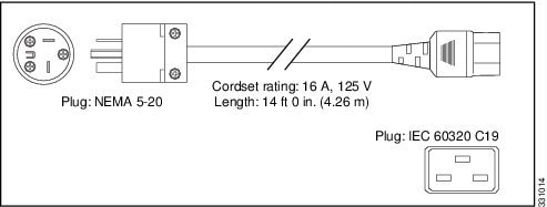
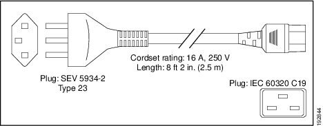
Table A-18 3-kW and 6-kW AC Power Supply Power Cords
|
|
|
|
Power Cord Reference Illustration
|
Australia and New Zealand |
CAB-AC-16A-AUS |
16A, 250 VAC |
Figure A-1 |
Peoples Republic of China |
CAB-AC-16A-CH |
16A, 250 VAC |
Figure A-2 |
Continental Europe |
CAB-AC-2500W-EU |
16A, 250 VAC |
Figure A-3 |
International |
CAB-AC-2500W-INT |
16A, 250 VAC |
Figure A-4 |
Israel |
CAB-AC-2500W-ISRL |
16A, 250 VAC |
Figure A-5 |
Japan and North America (non locking) 200-240 VAC operation |
CAB-9K16A-US1 |
16A, 250 VAC |
Figure A-6 |
Japan and North America (locking) 200-240 VAC operation |
CAB-AC-C6K-TWLK |
16A, 250 VAC |
Figure A-7 |
Japan and North America 100-120 VAC operation |
CAB-7513AC |
16A, 250 VAC |
Figure A-8 |
Korea |
CAB-9K16A-KOR |
16A, 250 VAC |
Figure A-9 |
Power distribution unit (PDU) |
CAB-C19-CBN |
16A, 250 VAC |
Figure A-10 |
Switzerland |
CAB-ACS-16 |
16A, 250 VAC |
Figure A-11 |
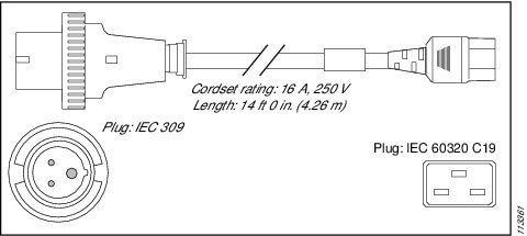
Figure A-1 CAB-AC-16A-AUS Power Cord and Plugs for the 3-kW and 6-kW AC Power Supply Unit
Figure A-2 CAB-AC-16A-CH Power Cord and Plugs for the 3-kW and 6-kW AC Power Supply Unit
Figure A-3 CAB-AC-2500W-EU Power Cord and Plugs for the 3-kW and 6-kW AC Power Supply Unit
Figure A-4 CAB-AC-2500W-INT Power Cord and Plugs for the 3-kW and 6-kW AC Power Supply Unit
Figure A-5 CAB-AC-2500W-ISRL Power Cord and Plugs for the 3-kW and 6-kW AC Power Supply Unit
Figure A-6 CAB-9K16A-US1 Power Cord and Plugs for the 3-kW and 6-kW AC Power Supply Unit
Figure A-7 CAB-AC-C6K-TWLK Power Cord and Plugs for the 3-kW and 6-kW AC Power Supply Unit
Figure A-8 CAB-7513AC Power Cord and Plugs for the 3-kW and 6-kW AC Power Supply Unit
Figure A-9 CAB-9K16A-KOR Power Cord and Plugs for the 3-kW and 6-kW AC Power Supply Unit
Figure A-10 CAB-C19-CBN Power Cord and Plugs for the 3-kW and 6-kW AC Power Supply Unit
Figure A-11 CAB-ACS-16 Power Cord and Plugs for the 3-kW and 6-kW AC Power Supply Unit
Figure A-12 CAB-AC-16A-AUS Power Cord and Plugs for the 3-kW and 6-kW AC Power Supply Unit
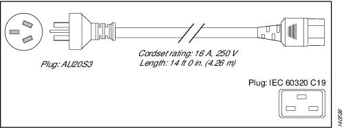
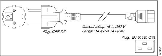
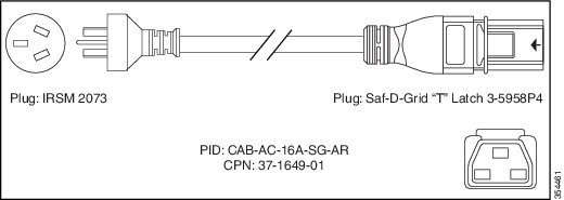
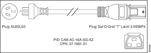
Table A-19 3.5-kW HVAC/HVDC Power Supply AC Power Cords
|
|
|
|
|
|
Power cord reference illustration
|
Argentina |
CAB-AC-16A-SG-AR |
37-1649-01 |
14' 0" (4.26 m) |
16A, 250 VAC |
Figure A-13 |
Australia and New Zealand |
CAB-AC-16A-SG-AZ |
37-1661-01 |
14' 0" (4.26 m) |
16A, 250 VAC |
Figure A-14 |
Brazil |
CAB-AC-16A-SG-BR |
37-1650-01 |
14' 0" (4.26 m) |
16A, 250 VAC |
Figure A-15 |
Peoples Republic of China |
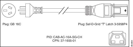
CAB-AC-16A-SG-CH |
37-1655-01 |
14' 0" (4.26 m) |
16A, 250 VAC |
Figure A-16 |
Continental Europe |
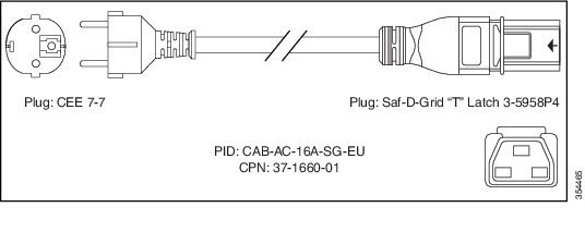
CAB-AC-16A-SG-EU |
37-1660-01 |
14' 0" (4.26 m) |
16A, 250 VAC |
Figure A-17 |
India |
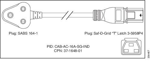
CAB-AC-16A-SG-IND |
37-1648-01 |
14' 0" (4.26 m) |
16A, 250 VAC |
Figure A-18 |
International |
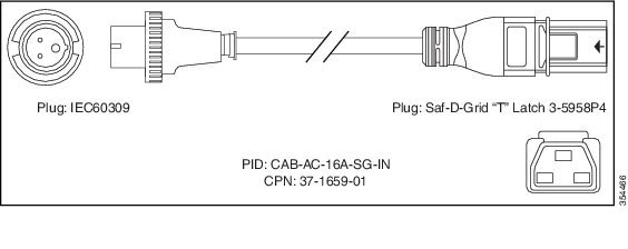
CAB-AC-16A-SG-IN |
37-1659-01 |
14' 0" (4.26 m) |
16A, 250 VAC |
Figure A-19 |
Israel |
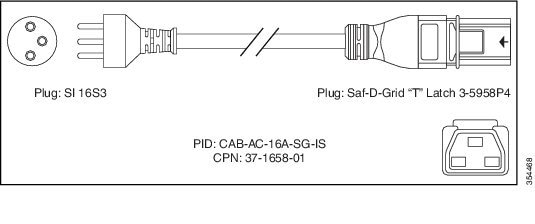
CAB-AC-16A-SG-IS |
37-1658-01 |
14' 0" (4.26 m) |
16A, 250 VAC |
Figure A-20 |
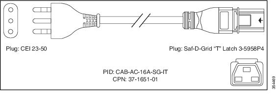
Italy |
CAB-AC-16A-SG-IT |
37-1651-01 |
14' 0" (4.26 m) |
16A, 250 VAC |
Figure A-21 |
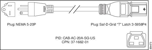
North America (non locking) 110 VAC operation |
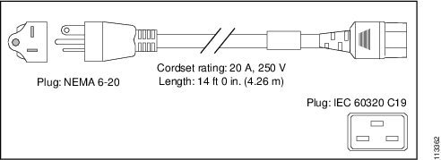
CAB-AC-20A-SG-US |
37-1662-01 |
14' 0" (4.26 m) |
20A, 110 VAC |
Figure A-22 |
North America (locking) 125 VAC operation |
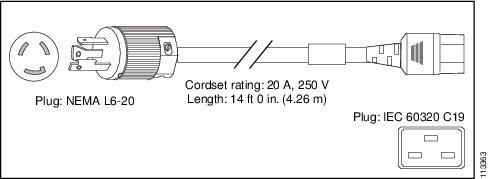
CAB-AC-20A-SG-US1 |
37-1652-01 |
14' 0" (4.26 m) |
20A, 125 VAC |
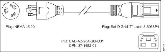
Figure A-23 |
North America (non locking) 200-240 VAC operation |
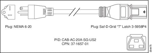
CAB-AC-20A-SG-US2 |
37-1657-01 |
14' 0" (4.26 m) |
20A, 250 VAC |
Figure A-24 |
North America (locking) 200-240 VAC operation |
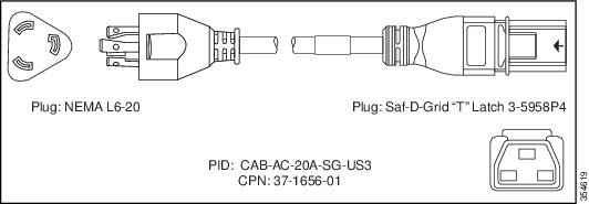
CAB-AC-20A-SG-US3 |
37-1656-01 |
14' 0" (4.26 m) |
20A, 250 VAC |
Figure A-25 |
North America 277 VAC operation |
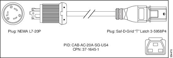
CAB-AC-20A-SG-US4 |
37-1645-01 |
14' 0" (4.26 m) |
20A, 277 VAC |
Figure A-26 |
North America Cabinet Jumper Power distribution unit (PDU) |
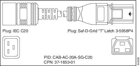
CAB-AC-20A-SG-C20 |
37-1653-01 |
14' 0" (4.26 m) |
20A, 250 VAC |
Figure A-27 |
South Africa |
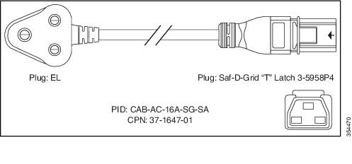
CAB-AC-16A-SG-SA |
37-1647-01 |
14' 0" (4.26 m) |
16A, 250 VAC |
Figure A-28 |
Korea |
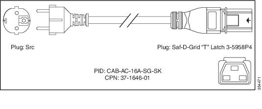
CAB-AC-16A-SG-SK |
37-1646-01 |
14' 0" (4.26 m) |
16A, 250 VAC |
Figure A-29 |
Switzerland |
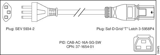
CAB-AC-16A-SG-SW |
37-1654-01 |
14' 0" (4.26 m) |
16A, 250 VAC |
Figure A-30 |
International, IEC/EU, Ring Terminal source plug |
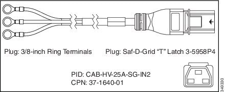
CAB-HV-25A-SG-IN2 |
37-1640-01 |
14' 0" (4.26 m) |
20A, 300 VAC/500 VDC |
Figure A-31 |
International, IEC/EU |
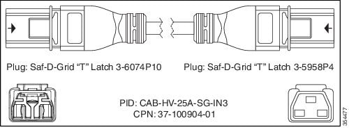
CAB-HV-25A-SG-IN3 |
37-100904-01 |
14' 0" (4.26 m) |
20A, 300 VAC |
Figure A-32 |
North America, Ring Terminal source plug |
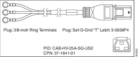
CAB-HV-25A-SG-US2 |
37-1641-01 |
14' 0" (4.26 m) |
20A, 300 VAC/500 VDC |
Figure A-33 |
North America |
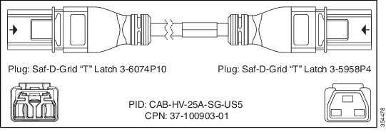
CAB-HV-25A-SG-US5 |
37-100903-01 |
14' 0" (4.26 m) |
20A, 300 VAC |
Figure A-34 |

Note All cables will not be orderable at first customer shipment (FCS).
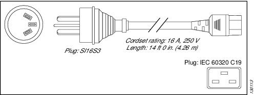
Figure A-13 CAB-AC-16A-SG-AR Power Cord and Plugs for the 3.5-kW HVAC/HVDC Power Supply Unit
Figure A-14 CAB-AC-16A-SG-AZ Power Cord and Plugs for the 3.5-kW HVAC/HVDC Power Supply Unit
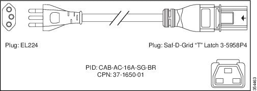
Figure A-15 CAB-AC-16A-SG-BR Power Cord and Plugs for the 3.5-kW HVAC/HVDC Power Supply Unit
Figure A-16 CAB-AC-16A-SG-CH Power Cord and Plugs for the 3.5-kW HVAC/HVDC Power Supply Unit
Figure A-17 CAB-AC-16A-SG-EU Power Cord and Plugs for the 3.5-kW HVAC/HVDC Power Supply Unit
Figure A-18 CAB-AC-16A-SG-IND Power Cord and Plugs for the 3.5-kW HVAC/HVDC Power Supply Unit
Figure A-19 CAB-AC-16A-SG-IN Power Cord and Plugs for the 3.5-kW HVAC/HVDC Power Supply Unit
Figure A-20 CAB-AC-16A-SG-IS Power Cord and Plugs for the 3.5-kW HVAC/HVDC Power Supply Unit
Figure A-21 CAB-AC-16A-SG-IT Power Cord and Plugs for the 3.5-kW HVAC/HVDC Power Supply Unit
Figure A-22 CAB-AC-20A-SG-US Power Cord and Plugs for the 3.5-kW HVAC/HVDC Power Supply Unit
Figure A-23 CAB-AC-20A-SG-US1 Power Cord and Plugs for the 3.5-kW HVAC/HVDC Power Supply Unit
Figure A-24 CAB-AC-20A-SG-US2 Power Cord and Plugs for the 3.5-kW HVAC/HVDC Power Supply Unit
Figure A-25 CAB-AC-20A-SG-US3 Power Cord and Plugs for the 3.5-kW HVAC/HVDC Power Supply Unit
Figure A-26 CAB-AC-20A-SG-US4 Power Cord and Plugs for the 3.5-kW HVAC/HVDC Power Supply Unit
Figure A-27 CAB-AC-20A-SG-C20 Power Cord and Plugs for the 3.5-kW HVAC/HVDC Power Supply Unit
Figure A-28 CAB-AC-16A-SG-SA Power Cord and Plugs for the 3.5-kW HVAC/HVDC Power Supply Unit
Figure A-29 CAB-AC-16A-SG-SK Power Cord and Plugs for the 3.5-kW HVAC/HVDC Power Supply Unit
Figure A-30 CAB-AC-16A-SG-SW Power Cord and Plugs for the 3.5-kW HVAC/HVDC Power Supply Unit
Figure A-31 CAB-HV-25A-SG-IN2 Power Cord and Plugs for the 3.5-kW HVAC/HVDC Power Supply Unit
Figure A-32 CAB-HV-25A-SG-IN3 Power Cord and Plugs for the 3.5-kW HVAC/HVDC Power Supply Unit
Figure A-33 CAB-HV-25A-SG-US2 Power Cord and Plugs for the 3.5-kW HVAC/HVDC Power Supply Unit
Figure A-34 CAB-HV-25A-SG-US5 Power Cord and Plugs for the 3.5-kW HVAC/HVDC Power Supply Unit
Table A-20 7.5-kW AC Power Supply Power Cord
|
|
|
|
Power cord reference illustration
|
Japan and North America |
N7K-AC-7.5KW-US |
30 A, 250 VAC |
Figure A-35 |
International |
N7K-AC-7.5KW-INT |
32 A, 250 VAC |
Figure A-36 |
Figure A-35 NEMA L6-30 Power Connector for the 7.5-kW AC Power Supply Unit
Figure A-36 IEC 603090 Power Connector for the 7.5-kW AC Power Supply Unit
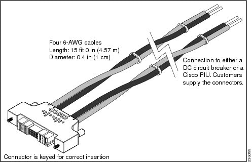
Table A-21 3-kW DC Power Supply Power Cord
|
|
|
|
|
All |
— |
45 A |
6 AWG |
Table A-22 3.5-kW HVAC/HVDC Power Supply DC Power Cords
|
|
|
|
|
|
Power Cord Reference Illustration
|
North America |
CAB-HV-25A-SG-US1 |
37-1643-01 |
14' 0" (4.26 m) |
20 A, 400 VDC |
Figure A-37 |
North America, Ring Terminal source plug |
CAB-HV-25A-SG-US2 |
37-1641-01 |
14' 0" (4.26 m) |
20 A, 300 VAC/500 VDC |
Figure A-38 |
International |
CAB-HV-25A-SG-IN1 |
37-1642-01 |
14' 0" (4.26 m) |
20 A, 400 VDC |
Figure A-39 |
International, Ring Terminal source plug |
CAB-HV-25A-SG-IN2 |
37-1640-01 |
14' 0" (4.26 m) |
20 A, 300 VAC/500 VDC |
Figure A-40 |
Note All cables will not be orderable at first customer shipment (FCS).
Figure A-37 CAB-HV-25A-SG-US1 Power Cord and Plugs for the 3.5-kW HVAC/HVDC Power Supply
Figure A-38 CAB-HV-25A-SG-US2 Power Cord and Plugs for the 3.5-kW HVAC/HVDC Power Supply
Figure A-39 CAB-HV-25A-SG-IN1 Power Cord and Plugs for the 3.5-kW HVAC/HVDC Power Supply Unit
Figure A-40 CAB-HV-25A-SG-IN2 Power Cord and Plugs for the 3.5-kW HVAC/HVDC Power Supply
Table A-23 6-kW DC Power Supply Power Cord
|
|
|
|
Power Cord Reference Illustration
|
All |
N7K-DC-CAB |
40 A, 48V-48V |
Figure A-41 |
Figure A-41 Power Connector for the 6.0-kW DC Power Supply Unit
Chassis Clearances
You must provide each Cisco Nexus 7000 Series switch with adequate clearance for installation, maintenance, cabling, and airflow. Installation clearance includes the cold aisle spacing required in front of the rack or cabinet to allow you to move the switch with a mechanical lift to its rack or cabinet. Maintenance clearance is the hot or cold aisle spacing required to replace supervisor, I/O, fabric, fan, and power supply modules. Cabling clearance provides the required space in front of the chassis (often within a cabinet) for cables to bend and connect to the chassis. Airflow clearance is typically the spacing on the left or right of the chassis for side-to-side airflow into and out of the chassis. If a chassis has front-to-back airflow, it uses the maintenance clearance for airflow instead of airflow clearance on the sides of the chassis.
This section includes the following topics:
Cisco Nexus 7004 Chassis Clearances
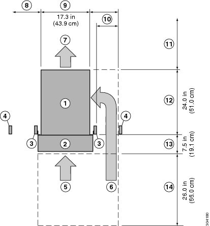
The Cisco Nexus 7004 chassis requires front clearance for cable management and maintenance, right side clearance for cooling air intake, and an unobstructed rear for exhausing air to the hot aisle behind the chassis. For the front, the cable management frames require 7.5 inches (19.1 cm) of clearance in front of the mounting rails and an additional 26 inches (66.0 cm) in front of the cable management frames or the cabinet door for maintenance. If you install the chassis with the optional center-mount bracket in place of the standard front-mount bracket, you must add 5.7 inches (14.4 cm) to the front clearance in front of the mounting rails on the rack. For cabinet installations, we recommend a right-side clearance of 11 inches (27.9 cm) between the switch and the inside of the cabinet. For rack installations, we recommend a right-side clearance of either 6 inches (15.2 cm) between racks or 11 inches (27.9 cm) between the chassis and a wall. The rear of the chassis must be unobstructed and open to the hot aisle in back of the switch for airflow exhaust. Figure A-42 shows the required clearances for a chassis in a four-post rack with a front-mount installation. Figure A-43 shows the required clearances for a chassis in a two-post rack with a front-mount installation. Figure A-44 shows the required clearances for chassis in a two-post rack with a center-mount installation.
Figure A-42 Clearances Required for the Cisco Nexus 7004 in a Four-Post Rack with Front-Mount Brackets
|
|
Chassis |
|
Chassis width |
|
|
Cable management frames |
|
Right side clearance recommended for cabinet installations:
|
|
|
Vertical rack-mount posts |
|
Right side clearance recommended for open rack installations:
- If next to another open rack, use 6 inches (15.2 cm) between racks.
- If next to a wall, use 11 inches (27.9 cm) between the chassis and the wall.
|
|
|
Vertical rack-mount posts for neighboring rack |
|
No rear clearance required but the rear must be open to the hot aisle to exhaust air |
|
|
Inside of cabinet (no left side clearance required) |
|
Airflow clearance required between the chassis and inside of cabinet (if a cabinet is used) |
|
|
Air intake from cold aisle for power supplies |
|
Chassis depth |
|
|
Air intake from cold aisle for the supervisor and I/O modules |
|
Clearance required between the front of the chassis and the inside of the cabinet (if used) or the edge of the cold aisle (if no cabinet) for the cable management frames and the optional front doors |
|
|
Air exhaust to hot aisle for all modules and power supplies |
|
Front service clearance required for installing the chassis and replacing the modules |
|
|
No left side clearance required (no airflow on left side) |
|
|
Figure A-43 Clearances Required for the Cisco Nexus 7004 in a Two-Post Rack with Front-Mount Brackets
|
|
Cisco Nexus 7004 chassis |
|
No left side clearance required (no airflow on left side) |
|
|
Cable management frames |
|
Chassis width. |
|
|
Vertical rack-mount posts |
|
Right side clearance recommended for open rack installations:
- If next to another open rack, use 6 inches (15.2 cm) between racks.
- If next to a wall, use 11 inches (27.9 cm) between the chassis and the wall.
|
|
|
Vertical rack-mount posts for neighboring racks |
|
No rear clearance required but the rear must be open to the hot aisle to exhaust air |
|
|
Air intake from cold aisle for power supplies |
|
Chassis depth |
|
|
Air intake from cold aisle for the supervisor and I/O modules |
|
Clearance required between the front of the chassis and the inside of the cabinet for the cable management frames and the optional front door |
|
|
Air exhaust to hot aisle for all modules and power supplies |
|
Front clearance required for installing the chassis and replacing the modules |
Figure A-44 Clearances Required for the Cisco Nexus 7004 in a Two-Post Rack with Center-Mount Brackets
|
|
Cisco Nexus 7004 chassis |
|
No left side clearance required (no airflow on left side) |
|
|
Cable management frames |
|
Chassis width |
|
|
Vertical rack-mount posts |
|
Right side clearance recommended for open rack installations:
- If next to another open rack, use 6 inches (15.2 cm) between racks.
- If next to a wall, use 11 inches (27.9 cm) between chassis and wall.
|
|
|
Vertical rack-mount posts for neighboring rack |
|
No rear clearance required but the rear must be open to the hot aisle to exhaust air |
|
|
Air intake from cold aisle for power supplies |
|
Distance from front of vertical rack-mount posts to rear of chassis |
|
|
Air intake from cold aisle for the supervisor and I/O modules |
|
Clearance required between the front of the chassis and the inside of the chassis for the cable management frames and the optional front doors |
|
|
Air exhaust to hot aisle for all modules and power supplies |
|
Front service clearance required for installing the chassis and replacing the modules |
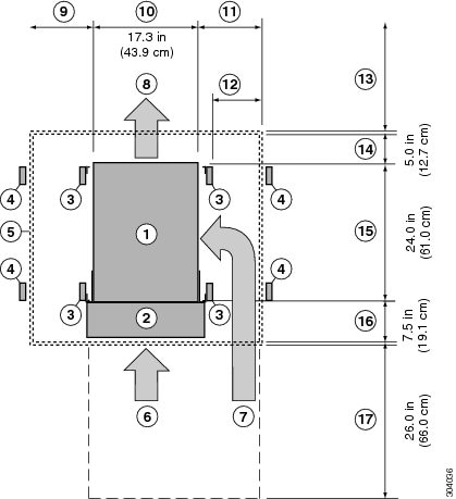
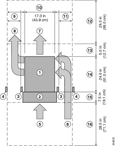
Cisco Nexus 7009 Chassis Clearances
The Cisco Nexus 7009 chassis has different clearance requirements for installations with four-post racks or cabinets, two-post racks with front-mount brackets, and two-post racks with center-mount brackets.
For four-post rack or cabinet installations, the chassis requires the following clearances (see Figure A-45):
- Front clearance requires both of the following:
– Cabling area of 7.5 inches (19.1 cm) between the front of the chassis and the inside surface of the cabinet or rack (this area can include the optional cable management frames)
– Maintenance area of 24 inches (61.1 cm) between the front of the rack or cabinet and the next object in the cold aisle.
Note You might need to increase the maintenance area to accommodate a wide mechanical lift used to move the chassis to or from the rack.
- Rear clearance includes both of the following:
– Cabling area of 7 inches (17.8 cm) between the rear of the chassis and the inside surface of the cabinet or rack
– Maintenance area of 24 inches (61.1 cm) between the rear of the rack or cabinet and the next object in the hot aisle
- Side clearance of 11 inches (27.9 cm) for air flow on each side of the chassis.
Figure A-45 Clearances Required for a Front-Mounted Cisco Nexus 7009 Chassis in a Four-Post Rack
|
|
Cisco Nexus 7009 chassis |
|
Left side clearance required with an unobstructed opening to the hot aisle to exhaust air |
|
|
Cable management frames |
|
Chassis width |
|
|
Vertical rack-mount post |
|
Side clearance recommended for cabinet installations:
|
|
|
Vertical rack-mount post for neighboring rack |
|
Side clearance recommended for open rack installations:
- If next to another open rack, use 6 inches (15.2 cm).
- If next to a wall, use 11 inches (27.9 cm).
|
|
|
Nearest object or inside of cabinet |
|
Rear service clearance required to replace fan trays and fabric modules |
|
|
Air intake from cold aisle for the power supplies |
|
Airflow clearance required between the chassis rear and inside of cabinet (if used) |
|
|
Air intake from cold aisle for the supervisor, fabric, and I/O modules |
|
Chassis depth |
|
|
Air exhaust to hot aisle for power supplies |
|
Clearance required between the front of the chassis and the inside of the cabinet (if used) or edge of cold aisle (if no cabinet) for the cable management frames and the optional front doors |
|
|
Air exhaust to hot aisle for the supervisor, fabric, and I/O modules |
|
Front clearance required for installing the chassis and replacing the modules |
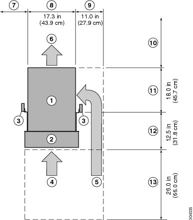
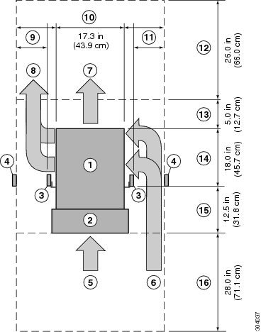
For two-post rack installations with front-mount brackets, the chassis requires the following clearances (see Figure A-46):
- Front clearance requires both of the following:
– Cabling area of 7.5 inches (19.1 cm) between the front of the chassis and the cold aisle (this area can include the optional cable management frames)
– Maintenance area of 28 inches (71.1 cm) in front of the cabling area for installing the chassis and replacing modules
Note You might need to increase the maintenance area to accommodate a wide mechanical lift used to move the chassis to or from the rack.
- Rear clearance requires 26 inches (66.0 cm) behind the chassis for cable management and for replacing modules and power supplies
- Side clearance recommendation depends on whether you use a rack or cabinet for the installation as follows:
– For cabinet installations, we recommend that you use 11 inches (27.9 cm) for airflow on each side of the chassis.
– For rack installations, we recommend 11 inches (27.9 cm) between the chassis and a wall or 6 inches (15.2 cm) between racks.
Figure A-46 Clearances Required for a Front-Mounted Cisco Nexus 7009 Chassis in a Two-Post Rack
|
|
Cisco Nexus 7009 chassis |
|
Side clearance required for open rack installations:
- If next to another open rack, use 6 inches (15.2 cm).
- If next to a wall, use 11 inches (27.9 cm).
|
|
|
Cable management frames |
|
Chassis width |
|
|
Vertical rack-mount post |
|
Side clearance required for open rack installations:
- If next to another open rack, use 6 inches (15.2 cm).
- If next to a wall, use 11 inches (27.9 cm).
|
|
|
Vertical rack-mount post for neighboring rack |
|
Rear service clearance required to replace fan trays and fabric modules |
|
|
Air intake from cold aisle for the power supplies |
|
Airflow clearance required between the chassis and inside of cabinet (if used) |
|
|
Air intake from cold aisle for the supervisor, fabric, and I/O modules |
|
Chassis depth |
|
|
Air exhaust to hot aisle for power supplies |
|
Clearance required between the front of the chassis and edge of cold aisle for the cable management frames and the optional front doors |
|
|
Air exhaust to hot aisle for the supervisor, fabric, and I/O modules |
|
Front clearance required for installing the chassis and replacing the modules |
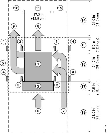
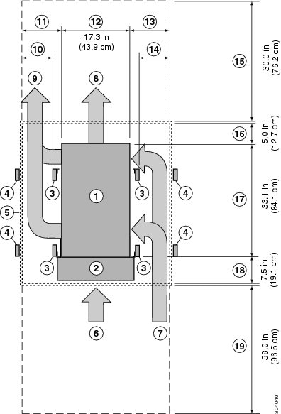
For two-post rack installations with center-mount brackets, the chassis requires the following clearances (see Figure A-47):
- Front clearance of 37 inches (94.0 cm) for both of the following:
– Cabling area of 13.5 inches (34.3 cm) between the front of the posts (posts are 6 inches (15.2 cm) behind the front of the chassis)
– Maintenance area of 26 inches (66.0 cm) in front of the cabling area for installing the chassis and replacing modules.
Note You might need to increase the maintenance area to accommodate a wide mechanical lift used to move the chassis to or from the rack.
- Rear clearance of 26 inches (66.0 cm) behind the chassis for cable management and for replacing the fan modules and power supplies.
- Side clearance of 11 inches (27.9 cm) for airflow on each side of the chassis.
Figure A-47 Clearances Required for a Center-Mounted Cisco Nexus 7009 Chassis in a Two-Post Rack
|
|
Cisco Nexus 7009 chassis |
|
Right side clearance (for rack installations) recommended to input air from the cold aisle:
- If next to another open rack, use 6 inches (15.2 cm).
- If next to a wall, use 11 inches (27.9 cm).
|
|
|
Cable management frames |
|
Chassis width |
|
|
Vertical rack-mount posts |
|
Right side clearance (for rack installations) recommended to input air from the cold aisle:
- If next to another open rack, use 6 inches (15.2 cm).
If next to a wall, use 11 inches (27.9 cm). |
|
|
Vertical rack-mount post for neighboring rack |
|
Rear service clearance required to replace fan trays and fabric modules |
|
|
Air intake from cold aisle for power supplies |
|
Airflow clearance required between the chassis and inside of cabinet (if used) |
|
|
Air intake from cold aisle for the supervisor, fabric, and I/O modules |
|
Chassis depth |
|
|
Air exhaust to hot aisle for the power supplies |
|
Clearance required between the front of the chassis and the front of the cable management frames and the optional front doors |
|
|
Air exhaust to hot aisle for the supervisor, fabric, and I/O modules |
|
Front service clearance required for installing the chassis and replacing the modules |
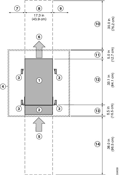
Cisco Nexus 7010 Chassis Clearances
The Cisco Nexus 7010 chassis requires the following clearances (see Figure A-48):
- Front clearance of 45.5 inches (115.6 cm) for both of the following:
– Cabling area of 7.5 inches (19.1 cm) between the front of the chassis and the inside of the cabinet or front of the rack
– Maintenance area of 38 inches (96.5 cm) of cold-aisle passageway in front of the rack or cabinet
Note You might need to increase the maintenance area to accommodate a wide mechanical lift used to move the chassis to or from the rack.
- Rear clearance of 35 inches (88.9 cm) for both of the following:
– Airflow area of 5 inches (12.7 cm) inside of the cabinet or rack
– Maintenance area of 30 inches (76.2 cm) of hot-aisle passageway behind the rack or cabinet
Figure A-48 Clearances Required for the Cisco Nexus 7010 Switch
Cisco Nexus 7018 Chassis Clearances
|
|
Cisco Nexus 7010 chassis |
|
Chassis width |
|
|
Cable management system |
|
No right side clearance required (no airflow on right side) |
|
|
Vertical rack-mount posts |
|
Rear service clearance required to replace fan trays and fabric modules |
|
|
Inside of cabinet (no side clearance required) |
|
Airflow clearance required between the chassis and inside of cabinet (if used) |
|
|
Air intake from cold aisle for all modules and power supplies |
|
Chassis depth, which includes the fan tray handles at the rear of the chassis |
|
|
Air exhaust to hot aisle for all modules and power supplies |
|
Clearance required between the front of the chassis and the inside of the cabinet (if used) or edge of the cold aisle (if no cabinet) for the cable management frames and the optional front doors |
|
|
No left side clearance required (no airflow on left side) |
|
Front service clearance required for installing the chassis and replacing the modules |
The Cisco Nexus 7018 chassis requires the following clearances (see Figure A-49):
- Front clearance of 45 inches (114.3 cm) for both of the following:
– Cabling area of 7.5 inches (19.1 cm) between the front of the chassis and the inside of the cabinet or front of the rack
– Maintenance area of 38 inches (96.5 cm) between the front of the rack or cabinet and the next rack, cabinet, or wall in the cold aisle (additional area might be needed for a larger mechanical lift used to move the chassis)
- Rear clearance of 35 inches (88.9 cm) for both of the following:
– Airflow area of 5 inches (12.7 cm) inside a cabinet (if used)
– Maintenance area of 30 inches (76.2 cm) of hot-aisle passageway behind the rack or cabinet
- Side clearance recommendation depends on whether a cabinet or rack is used:
– For cabinet installations, use 11 inches (27.9 cm) between the chassis and inside of the cabinet.
– For rack installations, use either 11” (27.9 cm) between the chassis and a wall or 6” (15.2 cm) between racks.
Figure A-49 Clearances Required for the Cisco Nexus 7018 Switch
|
|
Cisco Nexus 7018 chassis |
|
Side clearance recommended for cabinet installations::
|
|
|
Cable management frames |
|
Chassis width |
|
|
Vertical rack-mount post |
|
Side clearance recommended for cabinet installations::
|
|
|
Vertical rack-mount post for neighboring rack |
|
Side clearance recommended for open rack installations:
- If next to another open rack, use 6 inches (15.2 cm).
If next to a wall, use 11 inches (27.9 cm) |
|
|
Nearest object or inside of cabinet (side clearance required for airflow) |
|
Rear service clearance required to replace fan trays and fabric modules |
|
|
Air intake from cold aisle for the power supplies |
|
Airflow clearance required between the chassis and inside of cabinet (cabinet installations only) |
|
|
Air intake from cold aisle for the supervisor, fabric, and I/O modules |
|
Chassis depth |
|
|
Air exhaust to hot aisle for the power supplies |
|
Clearance required between the front of the chassis and the inside of the cabinet (cabinet installations) or edge of the cold aisle (rack installations) for the cable management frames and the optional front door |
|
|
Air exhaust to hot aisle for the supervisor, fabric, and I/O modules |
|
Front service clearance required for installing the chassis and replacing the modules |
|
|
Side clearance recommended for open rack installations:
- If next to another open rack, use 6 inches (15.2 cm).
- If next to a wall, use 11 inches (27.9 cm).
|
|
|
Facility Cooling Requirements
The Cisco Nexus 7000 Series switches dissipate considerable power that generates much heat. The following is the heat dissipation requirement for these switches:
- Cisco Nexus 7004 dissipates up to 9737 BTUs per hour
- Cisco Nexus 7009 dissipates up to 28,101 BTUs per hour
- Cisco Nexus 7010 dissipates up to 35,162 BTUs per hour
- Cisco Nexus 7018 dissipates up to 51,195 BTUs per hour
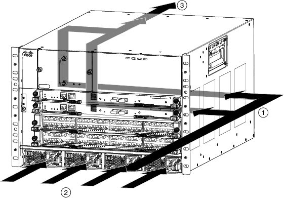
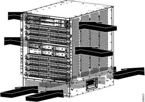
Chassis Airflow
The Cisco Nexus 7000 Series switches are designed to work in a hot-aisle/cold-aisle environment using front-to-back, side-to-side, or side-to-back airflow. Each of these switches uses one of the following airflow directions:
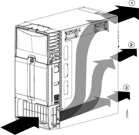
- The Cisco Nexus 7004 switch uses side-to-back airflow to cool its modules and front-to-back airflow to cool its power supplies as shown in Figure A-50. This switch requires right-side clearance for airflow into the chassis.
- The Cisco Nexus 7009 switch uses side-to-side airflow to cool its modules and front-to-back airflow to cool its power supplies as shown in Figure A-51. This switch requires right- and left-side clearance for airflow into and out of the chassis.
- The Cisco Nexus 7010 switch uses front-to-back airflow as shown in Figure A-52.
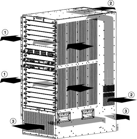
- The Cisco Nexus 7018 switch uses side-to-side airflow to cool its modules and front-to-back airflow to cool its power supply units as shown in Figure A-53. This switch requires right- and left-side clearance for airflow into and out of the chassis.
Figure A-50 Airflow for the Cisco Nexus 7004 Chassis
|
|
Right side-to-rear airflow for cooling supervisor and I/O modules |
|
Exhaust out the rear to the hot aisle |
|
|
Front-to-rear airflow for cooling power supplies |
|
|
Figure A-51 Airflow for the Cisco Nexus 7009 Chassis
|
|
Airflow for cooling the supervisor modules, I/O modules, and fabric modules |
|
Airflow for cooling the power supply units |
Figure A-52 Airflow for the Cisco Nexus 7010 Chassis
|
|
Airflow for cooling the supervisor and I/O modules |
|
Airflow for cooling the power supply units |
|
|
Airflow for cooling the fabric modules |
|
|
Figure A-53 Airflow for the Cisco Nexus 7018 Chassis
|
|
Airflow for cooling the supervisor and I/O modules |
|
Airflow for cooling the power supply units |
|
|
Airflow for cooling the fabric modules |
|
|
For the Cisco Nexus 7004 switch, you can route cables on the left or right side without interferring with coolant airflow, which goes in on the right side. Be sure to otherwise leave the right side unblocked so that cool air can flow from the cold aisle in the front to the chassis.
To allow for the Cisco Nexus 7009 and 7018 switches to take in air from the cold aisle and floor on the right side, you should route cables on the left front side of the switch. If necessary, you can route cables on the upper right front side of the chassis, which leaves the lower right side open to cooling air from the cold aisle in front of the chassis. By having the cables on the left side and leaving the left rear side unobstructed, the exhaust is directed to the hot aisle in back.
For the clearances required on each side of the switch, see the “Chassis Clearances” section.


 Feedback