- Preface
- Overview
- Installing a Cisco Nexus 7004 Switch
- Installing a Cisco Nexus 7009 Chassis
- Installing a Cisco Nexus 7010 Chassis
- Installing a Cisco Nexus 7018 Chassis
- Installing Power Supply Units
- Connecting the Cisco Nexus 7000 Switch to the Network
- Managing system hardware
- Troubleshooting
- Replacement Procedures
- Technical Specifications
- Transceiver and Module Connectors
- Cisco Nexus 7000 Series Accessory Kit Contents
- Chassis and Module LEDs
- Repacking the Nexus 7000 Series Switch for Shipment
- Site Preparation and Maintenance Records
- Replacing an AC Power Supply Unit During Operations
- Replacing a DC Power Supply Unit During Operations
- Replacing an HVAC/HVDC Power Supply Unit During Operations
- Replacing a Supervisor Module
- Required Tools
- Replacing a Redundant Supervisor Module During System Operations
- Replacing a Supervisor Module in a Single-Supervisor System
- Replacing Supervisor 1 Modules with Supervisor 2 or Supervisor 2E Modules
- Replacing Supervisor 2 Modules with Supervisor 2E Modules
- Upgrading Memory for Supervisor 1 Modules
Installing or Replacing Components
This chapter describes the replacement and other maintenance procedures for the Cisco Nexus 7000 Series switch components. You can also use these procedures for installing modules and other features purchased after you receive the switch.
A Cisco Nexus 7000 Series switch is designed for redundancy, which means that you can replace its modules, fan trays, and power supply units if there is at least one other of the same type operating during the replacement process.
This chapter includes the following sections:
- Replacing an AC Power Supply Unit During Operations
- Replacing a DC Power Supply Unit During Operations
- Replacing an HVAC/HVDC Power Supply Unit During Operations
- Replacing a Supervisor Module
- Installing an I/O Module
- Installing a NAM Module
- Replacing a Cisco Nexus 7009 Fabric Module During Operations
- Replacing or Upgrading a Cisco Nexus 7010 or 7018 Fabric Module During Operations
- Replacing the Cisco Nexus 7004 Fan Tray During Operations
- Replacing a Cisco Nexus 7009 Fan Tray During Operations
- Replacing a Cisco Nexus 7010 System Fan Tray During Operations
- Replacing a Cisco Nexus 7010 Fabric Fan Tray During System Operations
- Replacing a Cisco Nexus 7018 Fan Tray During System Operations
- Replacing Storage Media for a Supervisor Module
- Replacing the Cable Management Frames on the Cisco Nexus 7004 Chassis
- Replacing the Front Doors and Frame Assembly on the Cisco Nexus 7010 Chassis
- Replacing the Cable Management Frame on the Cisco Nexus 7018 Chassis
- Replacing the Front Door and Air Intake Assemblies on the Cisco Nexus 7018 Chassis
- Replacing the Air Filter on the Cisco Nexus 7004 Chassis
- Cleaning or Replacing the Air Filter for the Cisco Nexus 7010 Chassis
Replacing an AC Power Supply Unit During Operations
The Cisco Nexus 7000 Series switches use a load-balanced power supply that uses up to four AC, DC or HVAC/HVDC power supply units. The AC power supply units convert up to 1.2 kW, 1.4 kW, 3 kW, 3.5 kW, 6 kW, or 7.5 kW of AC power to DC power for system operations. If you can set one power supply unit in standby mode and have the required power load balanced by the remaining online power supply units, you can replace the standby power supply unit with another power supply unit without interrupting system operations.

Warning![]() Blank faceplates and cover panels serve three important functions: they prevent exposure to hazardous voltages and currents inside the chassis; they contain electromagnetic interference (EMI) that might disrupt other equipment; and they direct the flow of cooling air through the chassis. Do not operate the system unless all cards, faceplates, front covers, and rear covers are in place. Statement 1029
Blank faceplates and cover panels serve three important functions: they prevent exposure to hazardous voltages and currents inside the chassis; they contain electromagnetic interference (EMI) that might disrupt other equipment; and they direct the flow of cooling air through the chassis. Do not operate the system unless all cards, faceplates, front covers, and rear covers are in place. Statement 1029

Note![]() If a replacement power supply unit is not available and you do not have a blank plate to cover the empty power supply bay, you should leave the original power supply in the bay until you have the replacement unit.
If a replacement power supply unit is not available and you do not have a blank plate to cover the empty power supply bay, you should leave the original power supply in the bay until you have the replacement unit.
This section describes how to replace an AC power supply unit and includes the following topics:
- Removing a 3-kW AC Power Supply Unit During Operations
- Installing a 3-kW AC Power Supply Unit During Operations
- Removing a 6-kW or 7.5-kW AC Power Supply Unit During Operations
- Installing a 6-kW or 7.5-kW AC Power Supply Unit During Operations
Required Tools
Before you replace an AC power supply unit, make sure that you have the following tools and equipment:
- Number 1 Phillips screwdriver with torque capability
- Shipping materials
- Antistatic mat
- Replacement AC power supply unit

Removing a 3-kW AC Power Supply Unit During Operations
Warning![]() Hazardous voltage or energy is present on the backplane when the system is operating. Use caution when servicing. Statement 1034
Hazardous voltage or energy is present on the backplane when the system is operating. Use caution when servicing. Statement 1034
To replace an AC power supply unit while a Cisco Nexus 7000 Series switch is operating, follow these steps:
Step 1![]() Make sure that the power supply units not being replaced have their power turned on (labelled as 1 on the power switch).
Make sure that the power supply units not being replaced have their power turned on (labelled as 1 on the power switch).
Step 2![]() Turn the power switch on the power supply that you are removing to standby (labelled as 0).
Turn the power switch on the power supply that you are removing to standby (labelled as 0).
Step 3![]() Unplug the power cord from the AC power source. Release the retention clip over the plug.
Unplug the power cord from the AC power source. Release the retention clip over the plug.
Step 4![]() Press the release latch on the front right side of the power supply to the left and pull the power supply part way out of the chassis.
Press the release latch on the front right side of the power supply to the left and pull the power supply part way out of the chassis.
Step 5![]() Release the latch, place your other hand under the power supply, pull the module fully out of the chassis, and set it on the antistatic mat or pack it in a box for shipping.
Release the latch, place your other hand under the power supply, pull the module fully out of the chassis, and set it on the antistatic mat or pack it in a box for shipping.
Step 6![]() Either replace the power supply unit or cover the empty power supply bay as follows:
Either replace the power supply unit or cover the empty power supply bay as follows:
- If you are ready to replace the power supply unit, see the “Installing a 3-kW AC Power Supply Unit During Operations” section.
- If the power supply bay is to remain empty, install a blank power supply filler plate (Cisco part number 800-28658-01) over the opening, and secure it with the captive screws.
Installing a 3-kW AC Power Supply Unit During Operations
After you remove an AC power supply, you can replace it with another power supply or replace it with a blank plate until another power supply is available.
Warning![]() Hazardous voltage or energy is present on the backplane when the system is operating. Use caution when servicing. Statement 1034
Hazardous voltage or energy is present on the backplane when the system is operating. Use caution when servicing. Statement 1034
To install an AC power supply unit while a Cisco Nexus 7000 Series switch is operating, follow these steps:
Step 1![]() Unpack the replacement power supply unit and place it on an antistatic mat. You must also unpack a power cord to be used with the power supply.
Unpack the replacement power supply unit and place it on an antistatic mat. You must also unpack a power cord to be used with the power supply.
Step 2![]() Ensure that the power switch on the power supply unit is set to standby (labelled as 0) and that the AC and power cords are not plugged into the AC power supply.
Ensure that the power switch on the power supply unit is set to standby (labelled as 0) and that the AC and power cords are not plugged into the AC power supply.
Step 3![]() Holding the AC power supply unit with one hand on its handle and the other hand under the bottom (longest side), align the back of the power supply unit with the power supply bay and slide the power supply fully into the power supply bay until the release latch clicks.
Holding the AC power supply unit with one hand on its handle and the other hand under the bottom (longest side), align the back of the power supply unit with the power supply bay and slide the power supply fully into the power supply bay until the release latch clicks.
Step 4![]() Plug the power cable into the power jack on the front of the power supply unit. Pull down the retention clip over the plug on the power cable.
Plug the power cable into the power jack on the front of the power supply unit. Pull down the retention clip over the plug on the power cable.
Step 5![]() Plug the other end of the power cable into the AC power source. The Input LEDs light up.
Plug the other end of the power cable into the AC power source. The Input LEDs light up.
Step 6![]() Turn the Power switch from standby to on (from 0 to 1 as labelled on the power switch). The Output LED lights up.
Turn the Power switch from standby to on (from 0 to 1 as labelled on the power switch). The Output LED lights up.
If one or more of these LEDs is red, turn the power switch to standby (0), check the AC power connection, and then turn the power switch back on (1). The Input and Output LEDs for the connected power supply units should be green.
For more information about the power supply unit LED states, see Appendix D, “Chassis and Module LEDs.”
Removing a 6-kW or 7.5-kW AC Power Supply Unit During Operations
Warning![]() Hazardous voltage or energy is present on the backplane when the system is operating. Use caution when servicing. Statement 1034
Hazardous voltage or energy is present on the backplane when the system is operating. Use caution when servicing. Statement 1034
To replace an AC power supply unit while a Cisco Nexus 7000 Series switch is operating, follow these steps:
Step 1![]() Make sure that the power supply units not being replaced have their power switches turned to ON.
Make sure that the power supply units not being replaced have their power switches turned to ON.
Step 2![]() Turn the power switch on the power supply that you are removing to standby (STBY).
Turn the power switch on the power supply that you are removing to standby (STBY).
Step 3![]() Unplug the power cords from the AC power source. If the power supply unit has only one AC power cable, unplug just that cable. Otherwise, unplug both AC power cables.
Unplug the power cords from the AC power source. If the power supply unit has only one AC power cable, unplug just that cable. Otherwise, unplug both AC power cables.
Step 4![]() Unscrew the four captive screws on the power supply unit so that they are no longer in contact with the chassis.
Unscrew the four captive screws on the power supply unit so that they are no longer in contact with the chassis.
Step 5![]() With one hand on the handle of the power supply unit, pull the unit part way out of the chassis.
With one hand on the handle of the power supply unit, pull the unit part way out of the chassis.
Step 6![]() Place your other hand underneath the power supply unit to support its weight and then pull the unit fully out of the chassis.
Place your other hand underneath the power supply unit to support its weight and then pull the unit fully out of the chassis.
Step 7![]() Place the power supply unit on an antistatic mat or repack it in its original shipping materials. To repack a 6-kW AC power supply unit, see Figure 10-1. To repack a 7.5 kW AC power supply unit, see Figure 10-2.
Place the power supply unit on an antistatic mat or repack it in its original shipping materials. To repack a 6-kW AC power supply unit, see Figure 10-1. To repack a 7.5 kW AC power supply unit, see Figure 10-2.
Figure 10-1 Repacking a 6-kW AC Power Supply Unit
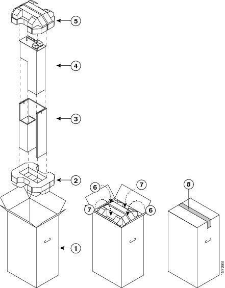
Figure 10-2 Repacking a 7.5 kW Power Supply Unit
Step 8![]() Either replace the power supply unit or cover the empty power supply bay as follows:
Either replace the power supply unit or cover the empty power supply bay as follows:
- If you are ready to replace the power supply unit, see the “Installing a 6-kW or 7.5-kW AC Power Supply Unit During Operations” section.
- If the power supply bay is to remain empty, install a blank power supply filler plate (Cisco part number 800-28658-01) over the opening, and secure it with the captive screws.
Installing a 6-kW or 7.5-kW AC Power Supply Unit During Operations
After you remove an AC power supply, you can replace it with another power supply or replace it with a blank plate until another power supply is available. If you need to install a DC power supply unit, see the “Installing a 6-kW DC Power Supply Unit During Operations” section.
Warning![]() Hazardous voltage or energy is present on the backplane when the system is operating. Use caution when servicing. Statement 1034
Hazardous voltage or energy is present on the backplane when the system is operating. Use caution when servicing. Statement 1034
To install an AC power supply unit while a Cisco Nexus 7000 Series switch is operating, follow these steps:
Step 1![]() Unpack the replacement power supply unit and place it on an antistatic mat. If you are unpacking a 6-kW power supply unit, you must also unpack one or two power cords. If you are unpacking a 7.5-kW power supply unit, two power cords are already attached to the power supply unit.
Unpack the replacement power supply unit and place it on an antistatic mat. If you are unpacking a 6-kW power supply unit, you must also unpack one or two power cords. If you are unpacking a 7.5-kW power supply unit, two power cords are already attached to the power supply unit.
Step 2![]() Ensure that the power switch on the power supply unit is in the standby (STBY) position and that the AC power cords are not plugged into the AC power supply.
Ensure that the power switch on the power supply unit is in the standby (STBY) position and that the AC power cords are not plugged into the AC power supply.
Step 3![]() Holding the AC power supply unit with one hand on its handle and the other hand under the bottom (longest side), align the back of the power supply unit with the power supply bay and slide the power supply into the power supply bay. Make sure the power supply unit is fully seated in the power supply bay and that its four captive screws are aligned with their holes in the chassis.
Holding the AC power supply unit with one hand on its handle and the other hand under the bottom (longest side), align the back of the power supply unit with the power supply bay and slide the power supply into the power supply bay. Make sure the power supply unit is fully seated in the power supply bay and that its four captive screws are aligned with their holes in the chassis.
Note![]() The 6-kW AC power supply unit weighs 22 pounds (10 kg), and the 7.5-kW AC power supply unit weighs 26.4 pounds (12 kg). Use two hands to safely hold and move a power supply unit.
The 6-kW AC power supply unit weighs 22 pounds (10 kg), and the 7.5-kW AC power supply unit weighs 26.4 pounds (12 kg). Use two hands to safely hold and move a power supply unit.
If you cannot push the power supply unit all the way into its bay, make sure that the power switch is turned to STBY before pushing the power supply unit all of the way into the bay.
Step 4![]() Screw in the four captive screws and tighten to 8 in-lb (0.9 N·m).
Screw in the four captive screws and tighten to 8 in-lb (0.9 N·m).
Step 5![]() Plug the power cables into the power jacks on the front of the power supply unit.
Plug the power cables into the power jacks on the front of the power supply unit.
- For 6-kW of power, plug two power cables into the two power jacks.
- For 3-kW of power, plug one power cable into one of the two power jacks.
Note![]() The 6-kW AC power supply unit does not ship with power cables attached to it, so you must attach one or two of those cables. If necessary, you can remove the cables from the AC power supply unit that you removed. The 7.5-kW AC power supply ships with permanently attached power cables, so you do not need to attach power cables to that power supply unit.
The 6-kW AC power supply unit does not ship with power cables attached to it, so you must attach one or two of those cables. If necessary, you can remove the cables from the AC power supply unit that you removed. The 7.5-kW AC power supply ships with permanently attached power cables, so you do not need to attach power cables to that power supply unit.
Step 6![]() Plug the power cables that are already attached to the power supply unit into the AC power source.
Plug the power cables that are already attached to the power supply unit into the AC power source.

Tip![]() For power redundancy, plug each power cable into a separate AC power supply circuit.
For power redundancy, plug each power cable into a separate AC power supply circuit.
Step 7![]() Turn the Power switch from STBY to ON.
Turn the Power switch from STBY to ON.
Step 8![]() Verify the power supply operation by checking that the power supply LEDs are in the following states:
Verify the power supply operation by checking that the power supply LEDs are in the following states:
- Input 1 LED is green.
- If a second AC power cord was connected, the Input 2 LED is green.
- Output LED is green.
- Fault LED is not on or flashing.
If one or more of these LEDs is red, turn the power switch to standby (STBY), check the AC power connections for the line in standby (STBY), and then turn the power switch back to ON. The Input and Output LEDs for the connected power supply units should be green.
For more information on the power supply unit LED states, see Appendix D, “Chassis and Module LEDs.”
Replacing a DC Power Supply Unit During Operations
The Cisco Nexus 7000 Series switches use a load-balanced power supply that uses up to three or four AC or DC power supply units. If you can set one power supply unit in standby mode and have the required power load balanced by the remaining online power supply units, then you can replace the standby power supply unit with another power supply unit without interrupting system operations.
Note![]() If a replacement power supply unit is not available and you do not have a blank plate to cover the empty power supply bay, you should leave the original power supply in the bay until you have the replacement unit.
If a replacement power supply unit is not available and you do not have a blank plate to cover the empty power supply bay, you should leave the original power supply in the bay until you have the replacement unit.
Warning![]() Blank faceplates and cover panels serve three important functions: they prevent exposure to hazardous voltages and currents inside the chassis; they contain electromagnetic interference (EMI) that might disrupt other equipment; and they direct the flow of cooling air through the chassis. Do not operate the system unless all cards, faceplates, front covers, and rear covers are in place. Statement 1029
Blank faceplates and cover panels serve three important functions: they prevent exposure to hazardous voltages and currents inside the chassis; they contain electromagnetic interference (EMI) that might disrupt other equipment; and they direct the flow of cooling air through the chassis. Do not operate the system unless all cards, faceplates, front covers, and rear covers are in place. Statement 1029
This section describes how to replace a DC power supply unit and includes the following topics:
- Removing a 3-kW DC Power Supply Unit During Operations
- Installing a 3-kW DC Power Supply Unit During Operations
- Removing a 6-kW DC Power Supply Unit During Operations
- Installing a 6-kW DC Power Supply Unit During Operations
Removing a 3-kW DC Power Supply Unit During Operations
You can remove a DC power supply during operations if the power supply is redundant and you can shut off the power from the grid without shutting off power to the other needed power supplies.
Warning![]() Hazardous voltage or energy is present on the backplane when the system is operating. Use caution when servicing. Statement 1034
Hazardous voltage or energy is present on the backplane when the system is operating. Use caution when servicing. Statement 1034
To replace a DC power supply unit while a Cisco Nexus 7000 Series switch is operating, follow these steps:
Step 1![]() Unpack the new power supply and keep its shipping materials so that you can use them to pack the old power supply.
Unpack the new power supply and keep its shipping materials so that you can use them to pack the old power supply.
Step 2![]() Make sure that the power supply units not being replaced have their power switches turned on (labelled as 1).
Make sure that the power supply units not being replaced have their power switches turned on (labelled as 1).
Step 3![]() For the power supply unit that you are replacing, turn its power switch to standby (labelled as 0). The Output LED turns off.
For the power supply unit that you are replacing, turn its power switch to standby (labelled as 0). The Output LED turns off.
Step 4![]() Turn off the DC input power by manually turning off the input circuit at the circuit breaker for this power supply.
Turn off the DC input power by manually turning off the input circuit at the circuit breaker for this power supply.
Step 5![]() Verify that the input power is completely off by making sure that all of the LEDs on the DC power supply unit are off.
Verify that the input power is completely off by making sure that all of the LEDs on the DC power supply unit are off.
Warning![]() Before performing any of the following procedures, ensure that power is removed from the DC circuit. Statement 1003
Before performing any of the following procedures, ensure that power is removed from the DC circuit. Statement 1003
Step 6![]() Detach each set of four DC power cables from the DC power source or DC power interface unit (PIU) as follows:
Detach each set of four DC power cables from the DC power source or DC power interface unit (PIU) as follows:
Warning![]() Hazardous voltage or energy may be present on DC power terminals. Always replace cover when terminals are not in service. Be sure uninsulated conductors are not accessible when cover is in place. Statement 1075
Hazardous voltage or energy may be present on DC power terminals. Always replace cover when terminals are not in service. Be sure uninsulated conductors are not accessible when cover is in place. Statement 1075
a.![]() Unscrew the three screws on top of the terminal box located on the front of the power supply, and remove the safety cover.
Unscrew the three screws on top of the terminal box located on the front of the power supply, and remove the safety cover.
b.![]() Unscrew the two nuts holding each cable lug, remove the lug, and refasten the two nuts. This action releases four cables from the power supply.
Unscrew the two nuts holding each cable lug, remove the lug, and refasten the two nuts. This action releases four cables from the power supply.
c.![]() Place the safety cover on the terminal box and fasten with three screws.
Place the safety cover on the terminal box and fasten with three screws.
Step 7![]() Press and hold the release latch on the front of the power supply and then pull the power supply part way out of the chassis by its handle.
Press and hold the release latch on the front of the power supply and then pull the power supply part way out of the chassis by its handle.
Step 8![]() Place your other hand under the power supply, fully pull it out of the chassis, and place it in its shipping materials.
Place your other hand under the power supply, fully pull it out of the chassis, and place it in its shipping materials.
Step 9![]() Either replace the power supply unit or cover the empty power supply bay as follows:
Either replace the power supply unit or cover the empty power supply bay as follows:
- If you are ready to replace the power supply unit, see the “Installing a 3-kW DC Power Supply Unit During Operations” section.
- If the power supply bay is to remain empty, install a blank power supply filler plate (Cisco part number 800-37248-01) over the opening, and secure it with its captive screws.
Installing a 3-kW DC Power Supply Unit During Operations
After you remove a 3-kW DC power supply, you can replace it with another AC or DC power supply or replace it with a blank plate until another power supply is available. To install an AC power supply unit, see the “Installing a 3-kW AC Power Supply Unit During Operations” section.
Warning![]() Hazardous voltage or energy is present on the backplane when the system is operating. Use caution when servicing. Statement 1034
Hazardous voltage or energy is present on the backplane when the system is operating. Use caution when servicing. Statement 1034
To install a 3-kW DC power supply unit while a Cisco Nexus 7000 Series switch is operating, follow these steps:
Step 1![]() If you have not already done so, unpack the replacement DC power supply unit and place it on an antistatic mat.
If you have not already done so, unpack the replacement DC power supply unit and place it on an antistatic mat.
Step 2![]() Ensure that the power switch on the replacement DC power supply unit is in the standby (0) position.
Ensure that the power switch on the replacement DC power supply unit is in the standby (0) position.
Step 3![]() Ensure that the DC power source for the new power supply unit is turned off at the circuit breaker.
Ensure that the DC power source for the new power supply unit is turned off at the circuit breaker.
Warning![]() Before performing any of the following procedures, ensure that power is removed from the DC circuit. Statement 1003
Before performing any of the following procedures, ensure that power is removed from the DC circuit. Statement 1003
Step 4![]() Grasp the power supply unit handle with one hand, and place your other hand underneath the power supply unit to support its weight. Align the back of the power supply unit with the power supply bay and slide the power supply all the way into the power supply bay until the release lever clicks. Make sure that the power supply unit does not pull out of the power supply bay without pressing the release lever.
Grasp the power supply unit handle with one hand, and place your other hand underneath the power supply unit to support its weight. Align the back of the power supply unit with the power supply bay and slide the power supply all the way into the power supply bay until the release lever clicks. Make sure that the power supply unit does not pull out of the power supply bay without pressing the release lever.
Step 5![]() If the power cables are not already connected to the DC power source, connect them as follows:
If the power cables are not already connected to the DC power source, connect them as follows:
a.![]() Unscrew the three screws on top of the terminal box located in front of the power supply, and remove the safety cover.
Unscrew the three screws on top of the terminal box located in front of the power supply, and remove the safety cover.
b.![]() Unscrew two nuts from each of the four terminal slots in the terminal box.
Unscrew two nuts from each of the four terminal slots in the terminal box.
c.![]() In each of two negative slots (labelled as -), place the lug on the end of a negative power cable, and fasten with two nuts. Tighten the nuts to 40 in-lb (4.5 N·m).
In each of two negative slots (labelled as -), place the lug on the end of a negative power cable, and fasten with two nuts. Tighten the nuts to 40 in-lb (4.5 N·m).
d.![]() In each of two positive slots (labelled as +), place the lug on the end of a positive power cable, and fasten with two nuts. Tighten the nuts to 40 in-lb (4.5 N·m).
In each of two positive slots (labelled as +), place the lug on the end of a positive power cable, and fasten with two nuts. Tighten the nuts to 40 in-lb (4.5 N·m).
e.![]() Place the safety cover on the terminal box and fasten with three screws.
Place the safety cover on the terminal box and fasten with three screws.
Step 6![]() Turn on the power at the DC power source circuit breaker. The input LEDs turn on when the circuit turns on.
Turn on the power at the DC power source circuit breaker. The input LEDs turn on when the circuit turns on.
Step 7![]() Turn the power switch on the DC power supply from standby (0) to on (1). The output LED turns on when power is being output to the switch.
Turn the power switch on the DC power supply from standby (0) to on (1). The output LED turns on when power is being output to the switch.
For information about how to connect the power supply unit to DC power sources for input source redundancy, see the “Connecting a DC Power Supply Directly to DC Power Sources” section).
Note![]() If the power source is not within reach of the power cables, connect the power cables to a DC power interface unit (PIU). To connect the PIU, see the “Connecting a Power Supply to DC Power Sources through a Power Interface Unit” section.
If the power source is not within reach of the power cables, connect the power cables to a DC power interface unit (PIU). To connect the PIU, see the “Connecting a Power Supply to DC Power Sources through a Power Interface Unit” section.
Warning![]() Hazardous voltage or energy may be present on DC power terminals. Always replace cover when terminals are not in service. Be sure uninsulated conductors are not accessible when cover is in place. Statement 1075
Hazardous voltage or energy may be present on DC power terminals. Always replace cover when terminals are not in service. Be sure uninsulated conductors are not accessible when cover is in place. Statement 1075
If one or more of the Input or Output LEDs is not green or the Fault LED is lit or flashing, see the “Troubleshooting a DC Power Supply Unit” section.
For more information on the power supply unit LED states, see Appendix D, “Chassis and Module LEDs.”
Removing a 6-kW DC Power Supply Unit During Operations
Warning![]() Hazardous voltage or energy is present on the backplane when the system is operating. Use caution when servicing. Statement 1034
Hazardous voltage or energy is present on the backplane when the system is operating. Use caution when servicing. Statement 1034
To replace a DC power supply unit while a Cisco Nexus 7000 Series switch is operating, follow these steps:
Step 1![]() Make sure that the power supply units not being replaced have their power switches turned to ON.
Make sure that the power supply units not being replaced have their power switches turned to ON.
Step 2![]() For the power supply unit that you are replacing, turn its power switch to STBY. The Output LED turns off.
For the power supply unit that you are replacing, turn its power switch to STBY. The Output LED turns off.
Step 3![]() Turn off the DC input power by manually turning off each input circuit at its circuit breaker.
Turn off the DC input power by manually turning off each input circuit at its circuit breaker.
Step 4![]() Verify that the input power is completely off by making sure that all of the LEDs on the DC power supply unit are off.
Verify that the input power is completely off by making sure that all of the LEDs on the DC power supply unit are off.
Warning![]() Before performing any of the following procedures, ensure that power is removed from the DC circuit. Statement 1003
Before performing any of the following procedures, ensure that power is removed from the DC circuit. Statement 1003
Step 5![]() Detach each set of four DC power cables from the DC power source or DC power interface unit (PIU) as follows:
Detach each set of four DC power cables from the DC power source or DC power interface unit (PIU) as follows:
Warning![]() Hazardous voltage or energy may be present on DC power terminals. Always replace cover when terminals are not in service. Be sure uninsulated conductors are not accessible when cover is in place. Statement 1075
Hazardous voltage or energy may be present on DC power terminals. Always replace cover when terminals are not in service. Be sure uninsulated conductors are not accessible when cover is in place. Statement 1075
Step 6![]() For each of the power plugs attached to the DC power supply unit, completely unscrew the two screws that hold it to the power supply unit, and then remove the plug from the power supply unit.
For each of the power plugs attached to the DC power supply unit, completely unscrew the two screws that hold it to the power supply unit, and then remove the plug from the power supply unit.
Step 7![]() Disconnect the grounding lug from the lower front side of the power supply unit by unscrewing the two M6 nuts and removing the lug from the power supply unit. For the location of the grounding pad on the DC power supply unit, see Figure 6-2.
Disconnect the grounding lug from the lower front side of the power supply unit by unscrewing the two M6 nuts and removing the lug from the power supply unit. For the location of the grounding pad on the DC power supply unit, see Figure 6-2.
Warning![]() When installing or replacing the unit, the ground connection must always be made first and disconnected last. Statement 1046
When installing or replacing the unit, the ground connection must always be made first and disconnected last. Statement 1046
Step 8![]() Holding the power supply handle with one hand, slide the power supply part of the way out of the chassis. Place your other hand underneath the power supply unit to support its weight and slide the power supply unit completely out of the chassis.
Holding the power supply handle with one hand, slide the power supply part of the way out of the chassis. Place your other hand underneath the power supply unit to support its weight and slide the power supply unit completely out of the chassis.
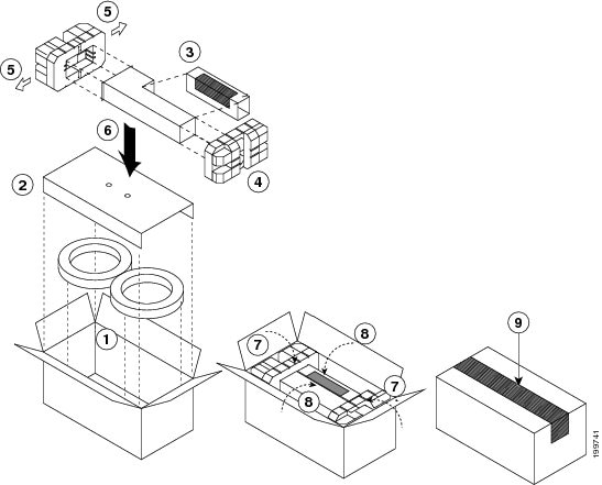
Step 9![]() Place the power supply unit on an antistatic mat or repack it in the box for its replacement unit as shown in Figure 10-3.
Place the power supply unit on an antistatic mat or repack it in the box for its replacement unit as shown in Figure 10-3.
Figure 10-3 Packing a DC Power Supply Unit
Step 10![]() Either replace the power supply unit or cover the empty power supply bay as follows:
Either replace the power supply unit or cover the empty power supply bay as follows:
- If you are ready to replace the power supply unit, see the “Installing a 6-kW DC Power Supply Unit During Operations” section.
- If the power supply bay is to remain empty, install a blank power supply filler plate (Cisco part number 800-28658-01) over the opening, and secure it with its captive screws.
Installing a 6-kW DC Power Supply Unit During Operations
After you remove a 6-kW DC power supply, you can replace it with another AC or DC power supply or replace it with a blank plate until another power supply is available. To install an AC power supply unit, see the “Installing a 6-kW or 7.5-kW AC Power Supply Unit During Operations” section.
Warning![]() Hazardous voltage or energy is present on the backplane when the system is operating. Use caution when servicing. Statement 1034
Hazardous voltage or energy is present on the backplane when the system is operating. Use caution when servicing. Statement 1034
To install a 6-kW DC power supply unit while a Cisco Nexus 7000 Series switch is operating, follow these steps:
Step 1![]() Unpack the replacement DC power supply unit and place it on an antistatic mat. Also, unpack the power cables.
Unpack the replacement DC power supply unit and place it on an antistatic mat. Also, unpack the power cables.
Step 2![]() Ensure that the power switch on the replacement DC power supply unit is in the standby (STBY) position.
Ensure that the power switch on the replacement DC power supply unit is in the standby (STBY) position.
Step 3![]() Ensure that the DC power source for the new power supply unit is turned off at the circuit breaker.
Ensure that the DC power source for the new power supply unit is turned off at the circuit breaker.
Warning![]() Before performing any of the following procedures, ensure that power is removed from the DC circuit. Statement 1003
Before performing any of the following procedures, ensure that power is removed from the DC circuit. Statement 1003
Step 4![]() Grasp the power supply unit handle with one hand, and place your other hand underneath the power supply unit to support its weight. Align the back of the power supply unit with the power supply bay and slide the power supply into the power supply bay. Make sure the power supply unit is fully seated in the power supply bay and that its four captive screws are aligned with their holes in the chassis.
Grasp the power supply unit handle with one hand, and place your other hand underneath the power supply unit to support its weight. Align the back of the power supply unit with the power supply bay and slide the power supply into the power supply bay. Make sure the power supply unit is fully seated in the power supply bay and that its four captive screws are aligned with their holes in the chassis.
Note![]() The 6-kW power supply unit weighs 21 lb (9.5 kg). Use two hands to safely hold and move a power supply unit.
The 6-kW power supply unit weighs 21 lb (9.5 kg). Use two hands to safely hold and move a power supply unit.
Step 5![]() Screw in each of the four captive screws and tighten to 8 in-lb (0.9 N·m).
Screw in each of the four captive screws and tighten to 8 in-lb (0.9 N·m).
Step 6![]() Attach the Earth ground to the power supply unit (see the “Grounding a 6-kW DC Power Supply” section).
Attach the Earth ground to the power supply unit (see the “Grounding a 6-kW DC Power Supply” section).
Warning![]() When installing or replacing the unit, the ground connection must always be made first and disconnected last. Statement 1046
When installing or replacing the unit, the ground connection must always be made first and disconnected last. Statement 1046
Step 7![]() If the power cables are not already connected to the DC power source, connect them as follows:
If the power cables are not already connected to the DC power source, connect them as follows:
- For 3 kW of power, connect one set of power cables (two sets of positive and negative cables attached to one plug) to the DC power circuit.
- For 6 kW of power, connect two sets of power cables (four sets of positive and negative cables attached to two plugs) to the DC power circuit.
For information on how to connect the power supply unit to DC power sources for input source redundancy, see the “Connecting a DC Power Supply Directly to DC Power Sources” section).
Note![]() If the power source is not within reach of the power cables, connect the power cables to a DC power interface unit (PIU). To connect the PIU, see the “Connecting a Power Supply to DC Power Sources through a Power Interface Unit” section.
If the power source is not within reach of the power cables, connect the power cables to a DC power interface unit (PIU). To connect the PIU, see the “Connecting a Power Supply to DC Power Sources through a Power Interface Unit” section.
Warning![]() Hazardous voltage or energy may be present on DC power terminals. Always replace cover when terminals are not in service. Be sure uninsulated conductors are not accessible when cover is in place. Statement 1075
Hazardous voltage or energy may be present on DC power terminals. Always replace cover when terminals are not in service. Be sure uninsulated conductors are not accessible when cover is in place. Statement 1075
Tip![]() For power redundancy, connect each set of power cables (each set with a common plug for the power supply unit) to a separate DC power circuit.
For power redundancy, connect each set of power cables (each set with a common plug for the power supply unit) to a separate DC power circuit.
Step 8![]() Attach the DC power cable plugs to the power supply unit and fasten them by tightening the captive screw on each end of the plug to 8 to 11 in-lb (0.9 to 1.2 N·m).
Attach the DC power cable plugs to the power supply unit and fasten them by tightening the captive screw on each end of the plug to 8 to 11 in-lb (0.9 to 1.2 N·m).
Step 9![]() Turn on the circuit breaker for the DC circuits that you connected.
Turn on the circuit breaker for the DC circuits that you connected.
Step 10![]() Turn the Power switch on the power supply unit from STBY to ON.
Turn the Power switch on the power supply unit from STBY to ON.
Step 11![]() Verify the power supply operation by checking that the power supply LEDs are in the following states:
Verify the power supply operation by checking that the power supply LEDs are in the following states:
- For 3 kW of output power, make sure that two Input LEDs are green.
- For 6 kW of output power, make sure that four Input LEDs are green.
- Output LED is green.
- Fault LED is not on or flashing.
If one or more of the Input or Output LEDs is not green or the Fault LED is lit or flashing, see the “Troubleshooting a DC Power Supply Unit” section.
For more information on the power supply unit LED states, see Appendix D, “Chassis and Module LEDs.”
Replacing an HVAC/HVDC Power Supply Unit During Operations
The Cisco Nexus 7000 Series switches use a load-balanced power supply that uses up to four AC, DC or HVAC/HVDC power supply units. If you can set one power supply unit in standby mode and have the required power load balanced by the remaining online power supply units, you can replace the standby power supply unit with another power supply unit without interrupting system operations.
Warning![]() Blank faceplates and cover panels serve three important functions: they prevent exposure to hazardous voltages and currents inside the chassis; they contain electromagnetic interference (EMI) that might disrupt other equipment; and they direct the flow of cooling air through the chassis. Do not operate the system unless all cards, faceplates, front covers, and rear covers are in place. Statement 1029
Blank faceplates and cover panels serve three important functions: they prevent exposure to hazardous voltages and currents inside the chassis; they contain electromagnetic interference (EMI) that might disrupt other equipment; and they direct the flow of cooling air through the chassis. Do not operate the system unless all cards, faceplates, front covers, and rear covers are in place. Statement 1029
Note![]() If a replacement power supply unit is not available and you do not have a blank plate to cover the empty power supply bay, you should leave the original power supply in the bay until you have the replacement unit.
If a replacement power supply unit is not available and you do not have a blank plate to cover the empty power supply bay, you should leave the original power supply in the bay until you have the replacement unit.
This section describes how to replace an AC power supply unit and includes the following topics:
- Removing a 3.5-kW HVAC/HVDC Power Supply Unit During Operations
- Installing a 3.5-kW HVAC/HVDC Power Supply Unit During Operations
Required Tools
Before you replace an HVAC/HVDC power supply unit, make sure that you have the following tools and equipment:
- Number 1 Phillips screwdriver with torque capability
- Shipping materials
- Antistatic mat
- Replacement power supply unit
Removing a 3.5-kW HVAC/HVDC Power Supply Unit During Operations
Warning![]() Hazardous voltage or energy is present on the backplane when the system is operating. Use caution when servicing. Statement 1034
Hazardous voltage or energy is present on the backplane when the system is operating. Use caution when servicing. Statement 1034
To replace an HVAC/HVDC power supply unit while a Cisco Nexus 7000 Series switch is operating, follow these steps:
Step 1![]() Make sure that the power supply units not being replaced have their power turned on (labelled as 1 on the power switch).
Make sure that the power supply units not being replaced have their power turned on (labelled as 1 on the power switch).
Step 2![]() Turn the power switch on the power supply that you are removing to standby (labelled as 0).
Turn the power switch on the power supply that you are removing to standby (labelled as 0).
Step 3![]() Unplug the power cord from the power source. Release the built-in latch on the plug.
Unplug the power cord from the power source. Release the built-in latch on the plug.
Step 4![]() Press the release latch on the front right side of the power supply to the left and pull the power supply part way out of the chassis.
Press the release latch on the front right side of the power supply to the left and pull the power supply part way out of the chassis.
Step 5![]() Release the latch, place your other hand under the power supply, pull the module fully out of the chassis, and set it on the antistatic mat or pack it in a box for shipping.
Release the latch, place your other hand under the power supply, pull the module fully out of the chassis, and set it on the antistatic mat or pack it in a box for shipping.
Step 6![]() Either replace the power supply unit or cover the empty power supply bay as follows:
Either replace the power supply unit or cover the empty power supply bay as follows:
- If you are ready to replace the power supply unit, see the “Installing a 3.5-kW HVAC/HVDC Power Supply Unit During Operations” section.
- If the power supply bay is to remain empty, install a blank power supply filler plate (Cisco part number 800-28658-01) over the opening, and secure it with the captive screws.
Installing a 3.5-kW HVAC/HVDC Power Supply Unit During Operations
After you remove a 3.5-kW HVAC/HVDC power supply, you can replace it with another power supply or replace it with a blank plate until another power supply is available.
Warning![]() Hazardous voltage or energy is present on the backplane when the system is operating. Use caution when servicing. Statement 1034
Hazardous voltage or energy is present on the backplane when the system is operating. Use caution when servicing. Statement 1034
To install an HVAC/HVDC power supply unit while a Cisco Nexus 7000 Series switch is operating, follow these steps:
Step 1![]() Unpack the replacement power supply unit and place it on an antistatic mat. You must also unpack a power cord to be used with the power supply.
Unpack the replacement power supply unit and place it on an antistatic mat. You must also unpack a power cord to be used with the power supply.
Step 2![]() Ensure that the power switch on the power supply unit is set to standby (labelled as 0) and that the HVAC/HVDC power cords are not plugged into the HVAC/HVDC power supply.
Ensure that the power switch on the power supply unit is set to standby (labelled as 0) and that the HVAC/HVDC power cords are not plugged into the HVAC/HVDC power supply.
Step 3![]() Holding the HVAC/HVDC power supply unit with one hand on its handle and the other hand under the bottom (longest side), align the back of the power supply unit with the power supply bay and slide the power supply fully into the power supply bay until the release latch clicks.
Holding the HVAC/HVDC power supply unit with one hand on its handle and the other hand under the bottom (longest side), align the back of the power supply unit with the power supply bay and slide the power supply fully into the power supply bay until the release latch clicks.
Step 4![]() Plug the power cable into the power jack on the front of the power supply unit. The built-in latch secures the power cable to the power supply.
Plug the power cable into the power jack on the front of the power supply unit. The built-in latch secures the power cable to the power supply.
Step 5![]() Plug the other end of the power cable into the HVAC/HVDC power source. The Input LEDs light up.
Plug the other end of the power cable into the HVAC/HVDC power source. The Input LEDs light up.
Step 6![]() Turn the Power switch from standby to on (from 0 to 1 as labelled on the power switch). The Output LED lights up.
Turn the Power switch from standby to on (from 0 to 1 as labelled on the power switch). The Output LED lights up.
If one or more of these LEDs is red, turn the power switch to standby (0), check the HVAC/HVDC power connection, and then turn the power switch back on (1). The Input and Output LEDs for the connected power supply units should be green.
For more information about the power supply unit LED states, see Appendix D, “Chassis and Module LEDs.”
Replacing a Supervisor Module
The Cisco Nexus 7000 Series switches can be configured with one or two supervisor modules. If the system has two supervisor modules, you can replace one of the supervisors while the other one manages system operations. If the system has only one supervisor, you must bring the system down to replace the supervisor module because the supervisor module is required for managing operations.
Note![]() If you need to bring down the switch to change supervisors, you must also copy the running configuration, system messages, VDC configurations, and licenses onto a USB drive before removing the supervisor module as explained in the “Replacing a Supervisor Module” section.
If you need to bring down the switch to change supervisors, you must also copy the running configuration, system messages, VDC configurations, and licenses onto a USB drive before removing the supervisor module as explained in the “Replacing a Supervisor Module” section.
To minimize the chance of accidentally disconnecting a module with a released lever, press the lever back toward the module until it clicks. If both levers are released, the system has disconnected and powered down the module, and the STATUS LED will be unlit. To reconnect and power up the module, either remove and reinsert the module in the chassis or use system commands to power it on.
This section describes how to replace supervisor modules and includes the following topics:
- Required Tools
- Replacing a Redundant Supervisor Module During System Operations
- Replacing a Supervisor Module in a Single-Supervisor System
- Replacing Supervisor 1 Modules with Supervisor 2 or Supervisor 2E Modules
- Replacing Supervisor 2 Modules with Supervisor 2E Modules
- Upgrading Memory for Supervisor 1 Modules
Required Tools
You need a flat-blade or number 2 Phillips-head screwdriver to loosen or tighten the captive screws on the supervisor module.
Replacing a Redundant Supervisor Module During System Operations
During operations, one supervisor is active while the other (redundant) supervisor is in standby mode. You can replace either of these two supervisors. If you need to replace the active supervisor, it becomes the standby supervisor as soon as you press its ejector buttons.
Note![]() A replacement supervisor module comes with one DIMM (4 GB of memory) or, if your switch is running Cisco NX-OS 5.1 (or later release), two DIMMs (8 GB of memory). If the switch not running a version of Cisco NX-OS that is compatible with using 8 GB of memory, then you must use only one DIMM (do not install an additional DIMM).
A replacement supervisor module comes with one DIMM (4 GB of memory) or, if your switch is running Cisco NX-OS 5.1 (or later release), two DIMMs (8 GB of memory). If the switch not running a version of Cisco NX-OS that is compatible with using 8 GB of memory, then you must use only one DIMM (do not install an additional DIMM).
Warning![]() Hazardous voltage or energy is present on the backplane when the system is operating. Use caution when servicing. Statement 1034
Hazardous voltage or energy is present on the backplane when the system is operating. Use caution when servicing. Statement 1034
To replace a supervisor module, follow these steps:
Step 1![]() Place an antistatic mat or antistatic foam where you can place the new and old supervisor modules.
Place an antistatic mat or antistatic foam where you can place the new and old supervisor modules.
Step 2![]() If the replacement supervisor is in a shipping box, prepare the module for installation by following these steps:
If the replacement supervisor is in a shipping box, prepare the module for installation by following these steps:
a.![]() Open the shipping box for the module and remove the module from its antistatic wrapping.
Open the shipping box for the module and remove the module from its antistatic wrapping.
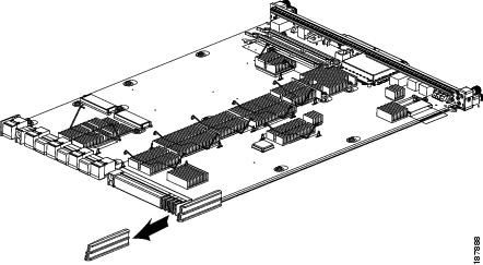
b.![]() If the plastic protector shown in Figure 10-4 is included with the module, remove it by pulling it past the back of the module. Keep the plastic protector and the other packing materials so that you can easily ship the module at a later time.
If the plastic protector shown in Figure 10-4 is included with the module, remove it by pulling it past the back of the module. Keep the plastic protector and the other packing materials so that you can easily ship the module at a later time.
Figure 10-4 Removing the Plastic Protector from the Supervisor Module
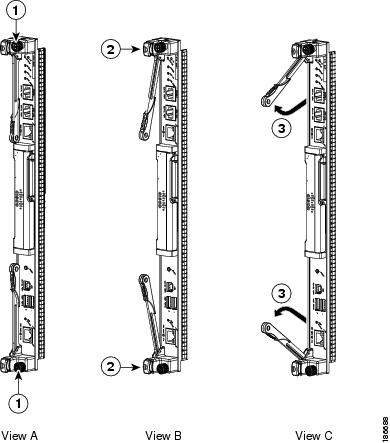
Step 3![]() On the currently installed supervisor module (the module that you are going to remove), loosen the two captive screws identified in View A of Figure 10-5.
On the currently installed supervisor module (the module that you are going to remove), loosen the two captive screws identified in View A of Figure 10-5.
Figure 10-5 Unseating a Supervisor Module
|
|
|
Simultaneously swing open both ejector levers to unseat the module. |
|
|
|
|
Step 4![]() Press the ejector release buttons on the ends of the module (see View B of Figure 10-5) to push out the ejector levers and to disconnect the module.
Press the ejector release buttons on the ends of the module (see View B of Figure 10-5) to push out the ejector levers and to disconnect the module.
If the chassis has two supervisor modules and you disconnect the active supervisor module, that supervisor goes into standby mode and the other supervisor automatically becomes the active supervisor.
Step 5![]() Disconnect the cables attached to the front of the module to be removed. Make sure that each cable is labelled for its port on the module.
Disconnect the cables attached to the front of the module to be removed. Make sure that each cable is labelled for its port on the module.
Step 6![]() Simultaneously rotate the two ejector levers outward to unseat the module from the midplane connector (see View C of Figure 10-5).
Simultaneously rotate the two ejector levers outward to unseat the module from the midplane connector (see View C of Figure 10-5).
Step 7![]() With a hand on each ejector, pull the module part way out of its slot in the chassis.
With a hand on each ejector, pull the module part way out of its slot in the chassis.
Step 8![]() Grasp the front edge of the module with your left hand and place your right hand under the lower side of the module to support its weight. Pull the module out of its slot.
Grasp the front edge of the module with your left hand and place your right hand under the lower side of the module to support its weight. Pull the module out of its slot.
Step 9![]() If you are removing the module from a Cisco Nexus 7010 chassis, rotate the module 90 degrees counterclockwise so that it is horizontal and you can see its circuitry from above.
If you are removing the module from a Cisco Nexus 7010 chassis, rotate the module 90 degrees counterclockwise so that it is horizontal and you can see its circuitry from above.
Step 10![]() Place the removed module in an antistatic bag.
Place the removed module in an antistatic bag.
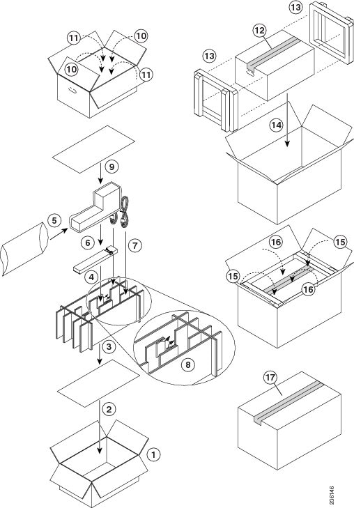
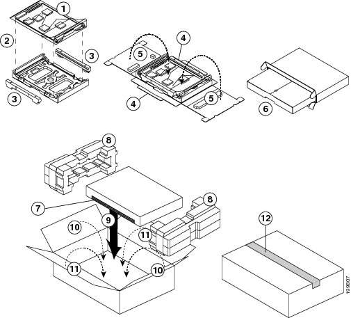
Step 11![]() Repack the bagged I/O module in its original packing materials as shown in Figure 10-6.
Repack the bagged I/O module in its original packing materials as shown in Figure 10-6.
Figure 10-6 Repacking a Supervisor Module
|
|
|
||
|
|
|
||
|
|
|
||
|
|
|
||
|
|
Fold the long flaps up along the ends of the module and then over the top of the module. Insert the two tabs on each flap into the side flaps. |
|
|
|
|
|
Step 12![]() On the replacement module, rotate both of the ejector levers away from the front of the module.
On the replacement module, rotate both of the ejector levers away from the front of the module.
Step 13![]() If you are inserting the module into a Cisco Nexus 7010 chassis, rotate the module 90 degrees clockwise.
If you are inserting the module into a Cisco Nexus 7010 chassis, rotate the module 90 degrees clockwise.
Step 14![]() Align the module to the chassis guides for the vacated slot (slot 5 or 6 on the Cisco Nexus 7010 chassis or slot 9 or 10 on the Cisco Nexus 7018 chassis), and slide the module part way into the slot.
Align the module to the chassis guides for the vacated slot (slot 5 or 6 on the Cisco Nexus 7010 chassis or slot 9 or 10 on the Cisco Nexus 7018 chassis), and slide the module part way into the slot.
Step 15![]() With one or both hands on the front of the module, push the module all the way into the slot until it seats on the midplane connector.
With one or both hands on the front of the module, push the module all the way into the slot until it seats on the midplane connector.
Step 16![]() Simultaneously push both ejector levers inward until they come in contact with the face of the module.
Simultaneously push both ejector levers inward until they come in contact with the face of the module.
The module should be fully seated in the slot and the captive screws should be aligned with their holes in the chassis. The EMI gasket should close the gap between the new module and the module in the next slot to the right.
Step 17![]() Screw in the two captive screws to the chassis and tighten them to 8 in-lb (0.9 N·m).
Screw in the two captive screws to the chassis and tighten them to 8 in-lb (0.9 N·m).
Step 18![]() Reconnect the console cable to the CONSOLE SERIAL PORT as explained in the “Connecting to the Console” section.
Reconnect the console cable to the CONSOLE SERIAL PORT as explained in the “Connecting to the Console” section.
Step 19![]() If the previous supervisor module was connected to an asynchronous device through a modem, connect the modem cable to the COM1/AUX SERIAL PORT as explained in the “Connecting to the Console” section.
If the previous supervisor module was connected to an asynchronous device through a modem, connect the modem cable to the COM1/AUX SERIAL PORT as explained in the “Connecting to the Console” section.
Step 20![]() Reconnect the network management cable to the MGMT ETH port as explained in “Setting Up the Management Interface” section.
Reconnect the network management cable to the MGMT ETH port as explained in “Setting Up the Management Interface” section.
Step 21![]() Reconnect the CMP cable to the CMP MGMT ETH port as explained in “Connecting the Supervisor CMP Port” section.
Reconnect the CMP cable to the CMP MGMT ETH port as explained in “Connecting the Supervisor CMP Port” section.
Step 22![]() Copy the license file from the active supervisor to the standby supervisor. Use the copy bootflash:license-filename.lic bootflash://supervisor-standby/license-filename.lic.lic command to copy the license file.
Copy the license file from the active supervisor to the standby supervisor. Use the copy bootflash:license-filename.lic bootflash://supervisor-standby/license-filename.lic.lic command to copy the license file.
Step 23![]() Verify that both supervisors have the same amount of memory by following these steps:
Verify that both supervisors have the same amount of memory by following these steps:
a.![]() Use the show system resources command to see how much memory is installed in the active supervisor.
Use the show system resources command to see how much memory is installed in the active supervisor.
b.![]() Use the system switchover command to make the other supervisor module active.
Use the system switchover command to make the other supervisor module active.
c.![]() Use the show system resources command to see how much memory is installed in the other supervisor.
Use the show system resources command to see how much memory is installed in the other supervisor.
If one of the supervisor modules has more memory than the other supervisor module, you must either remove 4 GB from the module with 8 GB (see the “Removing 4 GB of Memory from a Supervisor Module” section) or add 4 GB to the module with 4 GB (see the“Adding 4 GB of Memory to a Supervisor Module” section).
Replacing a Supervisor Module in a Single-Supervisor System
If you need to replace the supervisor in a single-supervisor Cisco Nexus 7000 Series system, you must shut down the system before replacing the supervisor.
Note![]() A replacement supervisor module comes with one DIMM (4 GB of memory) or, if your switch is running Cisco NX-OS 5.1 (or later release), two DIMMs (8 GB of memory). If the switch not running a version of Cisco NX-OS that is compatible with using 8 GB of memory, you must use only one DIMM (do not install an additional DIMM).
A replacement supervisor module comes with one DIMM (4 GB of memory) or, if your switch is running Cisco NX-OS 5.1 (or later release), two DIMMs (8 GB of memory). If the switch not running a version of Cisco NX-OS that is compatible with using 8 GB of memory, you must use only one DIMM (do not install an additional DIMM).
Warning![]() Hazardous voltage or energy is present on the backplane when the system is operating. Use caution when servicing. Statement 1034
Hazardous voltage or energy is present on the backplane when the system is operating. Use caution when servicing. Statement 1034
To replace a supervisor module in a single-supervisor system, follow these steps:
Step 1![]() Place an antistatic mat or antistatic foam where you can place the new and old supervisor modules.
Place an antistatic mat or antistatic foam where you can place the new and old supervisor modules.
Step 2![]() If the replacement supervisor is in a shipping box, prepare the module for installation by following these steps:
If the replacement supervisor is in a shipping box, prepare the module for installation by following these steps:
a.![]() Open the shipping box for the module and remove the module from its antistatic wrapping.
Open the shipping box for the module and remove the module from its antistatic wrapping.
b.![]() If the plastic protector shown in Figure 10-7 is included with the module, remove it by pulling it past the back of the module. Keep the plastic protector and the other packing materials so that you can easily ship the module at a later time.
If the plastic protector shown in Figure 10-7 is included with the module, remove it by pulling it past the back of the module. Keep the plastic protector and the other packing materials so that you can easily ship the module at a later time.
Figure 10-7 Removing the Plastic Protector from the Supervisor Module
Step 3![]() Turn off the power on each of the power supply unit by turning its power switch to standby (STBY).
Turn off the power on each of the power supply unit by turning its power switch to standby (STBY).
Step 4![]() Disconnect all of the cables attached to the front of the module to be removed.
Disconnect all of the cables attached to the front of the module to be removed.
Step 5![]() Loosen the two captive screws identified in View A of Figure 10-5.
Loosen the two captive screws identified in View A of Figure 10-5.
Step 6![]() Press the ejector release buttons on the top and bottom ends of the module (see View B of Figure 10-5) to push out the ejector levers and to disconnect the module.
Press the ejector release buttons on the top and bottom ends of the module (see View B of Figure 10-5) to push out the ejector levers and to disconnect the module.
Step 7![]() Simultaneously rotate the two ejector levers outward to unseat the module from the midplane connector (see View C of Figure 10-5).
Simultaneously rotate the two ejector levers outward to unseat the module from the midplane connector (see View C of Figure 10-5).
Step 8![]() With a hand on each ejector, pull the module part way out of its slot in the chassis.
With a hand on each ejector, pull the module part way out of its slot in the chassis.
Step 9![]() Grasp the front edge of the module with your left hand and place your right hand under the lower side of the module to support its weight. Pull the module out of its slot.
Grasp the front edge of the module with your left hand and place your right hand under the lower side of the module to support its weight. Pull the module out of its slot.
Step 10![]() If you are removing a module from a Cisco Nexus 7010 chassis, rotate the module 90 degrees counterclockwise so that it is horizontal and you can see its circuitry from above.
If you are removing a module from a Cisco Nexus 7010 chassis, rotate the module 90 degrees counterclockwise so that it is horizontal and you can see its circuitry from above.
Step 11![]() Place the removed module on the antistatic mat or repack it in its original packing materials as shown in Figure 10-6.
Place the removed module on the antistatic mat or repack it in its original packing materials as shown in Figure 10-6.
Step 12![]() On the replacement supervisor module, rotate both of the ejector levers away from the front of the module.
On the replacement supervisor module, rotate both of the ejector levers away from the front of the module.
Step 13![]() If you are inserting the module into a Cisco Nexus 7010 chassis, rotate the module 90 degrees clockwise.
If you are inserting the module into a Cisco Nexus 7010 chassis, rotate the module 90 degrees clockwise.
Step 14![]() Align the module to the chassis guides for the vacated slot (slot 5 or 6 on a Cisco Nexus 7010 chassis or slot 9 or 10 on a Cisco Nexus 7018 chassis), and slide the module part way into the slot.
Align the module to the chassis guides for the vacated slot (slot 5 or 6 on a Cisco Nexus 7010 chassis or slot 9 or 10 on a Cisco Nexus 7018 chassis), and slide the module part way into the slot.
Step 15![]() With one or both hands on the front of the module, push the module all the way into the slot until it seats on the midplane connector.
With one or both hands on the front of the module, push the module all the way into the slot until it seats on the midplane connector.
Step 16![]() Slide the module into the slot until it seats on the midplane.
Slide the module into the slot until it seats on the midplane.
Step 17![]() Simultaneously push both ejector levers inward until they come in contact with the face of the module.
Simultaneously push both ejector levers inward until they come in contact with the face of the module.
The module should be fully seated in the slot and the captive screws should be aligned with their holes in the chassis. The EMI gasket should close the gap between the replacement module and the module in the next slot.
Step 18![]() Screw in the two captive screws to the chassis and tighten them to 8 in-lb (0.9 N·m).
Screw in the two captive screws to the chassis and tighten them to 8 in-lb (0.9 N·m).
Step 19![]() Reconnect the console cable to the CONSOLE SERIAL PORT as explained in the “Connecting to the Console” section.
Reconnect the console cable to the CONSOLE SERIAL PORT as explained in the “Connecting to the Console” section.
Step 20![]() (For Supervisor 1 modules only) If the previous supervisor module was connected to an asynchronous device through a modem, connect the modem cable to the COM1/AUX SERIAL PORT as explained in the “Connecting to the Console” section.
(For Supervisor 1 modules only) If the previous supervisor module was connected to an asynchronous device through a modem, connect the modem cable to the COM1/AUX SERIAL PORT as explained in the “Connecting to the Console” section.
Step 21![]() Reconnect the network management cable to the MGMT ETH port as explained in the “Setting Up the Management Interface” section.
Reconnect the network management cable to the MGMT ETH port as explained in the “Setting Up the Management Interface” section.
Step 22![]() (For Supervisor 1 modules only) Reconnect the CMP cable to the CMP MGMT ETH port as explained in the “Connecting the Supervisor CMP Port” section.
(For Supervisor 1 modules only) Reconnect the CMP cable to the CMP MGMT ETH port as explained in the “Connecting the Supervisor CMP Port” section.
Replacing Supervisor 1 Modules with Supervisor 2 or Supervisor 2E Modules
Before migrating from Supervisor 1 modules to Supervisor 2 or Supervisor 2E modules, note the following guidelines:
- This migration process is disruptive for switches with one or two supervisor modules because the power must be turned off for the switch.
- Backward migration procedure (migrating from Supervisor 2 or Supervisor 2E modules to Supervisor 1 modules) is not provided.
- We recommend that you use Cisco NX-OS Release 5.2 (or later release) on the Supervisor 1 module while performing the migration.
- You cannot mix Supervisor 2 and Supervisor 2E modules in a production environment (this mix of modules is supported only while you are migrating from using Supervisor 2 modules to Supervisor 2E modules as explained in the “Replacing Supervisor 2 Modules with Supervisor 2E Modules” section). You must replace redundant Supervisor 1 modules with either two Supervisor 2 modules or two Supervisor 2E modules.
- If you plan to enable the admin VDC feature on the Supervisor 2 or Supervisor 2E modules, be sure to complete the entire migration procedure before enabling this feature (see the Cisco Nexus 7000 Series NX-OS Virtual Device Context Configuration Guide).
- The default-gateway command needs to be removed and replaced with ip route under the cmp-mgmt interface when SUP1 is upgraded to SUP-2/SUP-2E.
- If you are migrating Supervisor 1 Modules with Supervisor 2 or Supervisor 2E Modules, then replace ip default-gateway x.x.x.x' with ip route 0/0 x.x.x.x in the config.
To migrate from using Supervisor 1 modules to Supervisor 2 or Supervisor 2E modules, follow these steps:
Step 1![]() Insert a USB drive in the top USB port (usb1) in the active supervisor 1 module. If the Supervisor 2 or Supervisor 2E module shipped with an extra USB drive, you can insert that USB drive in the usb1 drive on the Supervisor 1 module.
Insert a USB drive in the top USB port (usb1) in the active supervisor 1 module. If the Supervisor 2 or Supervisor 2E module shipped with an extra USB drive, you can insert that USB drive in the usb1 drive on the Supervisor 1 module.
Note![]() Do not use the USB drive that is in the LOG FLASH port.
Do not use the USB drive that is in the LOG FLASH port.
Step 2![]() Format the drive by using the format command.
Format the drive by using the format command.
Step 3![]() Copy all of the VDC configurations for the switch to the USB drive by using the copy running-config command.
Copy all of the VDC configurations for the switch to the USB drive by using the copy running-config command.
Step 4![]() Backup the installed licenses for the switch to the USB drive by using the copy licenses command.
Backup the installed licenses for the switch to the USB drive by using the copy licenses command.
Note![]() You must use the tar extension for the archive file. This file will contain all of the license files that were installed on the Supervisor 1 module.
You must use the tar extension for the archive file. This file will contain all of the license files that were installed on the Supervisor 1 module.
Step 5![]() Determine the Cisco NX-OS software release to use on the Supervisor 2 or Supervisor 2E modules. We support Cisco NX-OS Release 6.1(1) (or later release) on those modules but another one might be recommended. Additionally, the most recommended maintenance release might not be the one that ships with the Supervisor 2 or Supervisor 2E modules. We recommend that you check with the following documents for the recommended software release:
Determine the Cisco NX-OS software release to use on the Supervisor 2 or Supervisor 2E modules. We support Cisco NX-OS Release 6.1(1) (or later release) on those modules but another one might be recommended. Additionally, the most recommended maintenance release might not be the one that ships with the Supervisor 2 or Supervisor 2E modules. We recommend that you check with the following documents for the recommended software release:
- Minimum Recommended Cisco NX-OS Releases for Cisco Nexus 7000 Series Switches
- Cisco Nexus 7000 Series NX-OS Release Notes, Release 6.1
Step 6![]() Copy the Supervisor 2 or Supervisor 2E version of the kickstart, system, and EPLD (optional) images to the USB drive by using the copy command.
Copy the Supervisor 2 or Supervisor 2E version of the kickstart, system, and EPLD (optional) images to the USB drive by using the copy command.
Note![]() This example specifies the NX-OS Release 6.1(1) images. For a later release, use the later release number in the.bin or.img file name.
This example specifies the NX-OS Release 6.1(1) images. For a later release, use the later release number in the.bin or.img file name.
Note![]() Although the Supervisor 2 and Supervisor 2E ship with updated EPLD images, you might need to update the EPLD images on the other modules on the switch. For example, migrating from Supervisor 1 modules to Supervisor 2 or Supervisor 2E modules on switches that use Fabric 2 modules requires EPLD updates for the fabric modules. For more information, see the Cisco Nexus 7000 Series FPGA/EPLD Upgrade Release Notes, Release 6.1 or later release.
Although the Supervisor 2 and Supervisor 2E ship with updated EPLD images, you might need to update the EPLD images on the other modules on the switch. For example, migrating from Supervisor 1 modules to Supervisor 2 or Supervisor 2E modules on switches that use Fabric 2 modules requires EPLD updates for the fabric modules. For more information, see the Cisco Nexus 7000 Series FPGA/EPLD Upgrade Release Notes, Release 6.1 or later release.
Step 7![]() Turn off the power to the switch by turning the power switch on each power supply from ON to STBY (Standby). The Output LED turns off on each power supply and the Status LEDs turn off on all of the supervisor and I/O modules.
Turn off the power to the switch by turning the power switch on each power supply from ON to STBY (Standby). The Output LED turns off on each power supply and the Status LEDs turn off on all of the supervisor and I/O modules.
Step 8![]() For each Supervisor 1 module installed in the switch, remove the module and replace it with a Supervisor 2 or Supervisor 2E module as explained one of the following sections:
For each Supervisor 1 module installed in the switch, remove the module and replace it with a Supervisor 2 or Supervisor 2E module as explained one of the following sections:
- If you are replacing both supervisors in a switch, see the “Replacing a Redundant Supervisor Module During System Operations” section.
- If you are replacing a supervisor module in a switch with one supervisor, see the “Replacing a Supervisor Module in a Single-Supervisor System” section.
Step 9![]() Power up the switch by turning the power switch on each of its power supplies from STBY (standby) to ON. The Output LED on each power supply turns on and eventually turns green when the power supply is sending power to the switch. The Status LED on each installed supervisor module also turns on when the module begins to turn on. The supervisor that becomes active has a green ACTIVE LED (the standby supervisor module has an amber ACTIVE LED).
Power up the switch by turning the power switch on each of its power supplies from STBY (standby) to ON. The Output LED on each power supply turns on and eventually turns green when the power supply is sending power to the switch. The Status LED on each installed supervisor module also turns on when the module begins to turn on. The supervisor that becomes active has a green ACTIVE LED (the standby supervisor module has an amber ACTIVE LED).
Step 10![]() Remove the USB drive from the Supervisor 1 module (this drive has copies of the Supervisor 1 configuration, license, and software images) and insert it in the Slot0: USB port on the active Supervisor 2 or Supervisor 2E module (ACTIVE LED is green).
Remove the USB drive from the Supervisor 1 module (this drive has copies of the Supervisor 1 configuration, license, and software images) and insert it in the Slot0: USB port on the active Supervisor 2 or Supervisor 2E module (ACTIVE LED is green).
Step 11![]() Connect a console to the active supervisor module as explained in “Connecting to the Console” section.
Connect a console to the active supervisor module as explained in “Connecting to the Console” section.
Step 12![]() If you are setting up the initial configuration for the supervisor module, the initial setup script will ask you if you want to enforce the secure password standard. Make your selection, enter your password, and then confirm the password by entering it again.
If you are setting up the initial configuration for the supervisor module, the initial setup script will ask you if you want to enforce the secure password standard. Make your selection, enter your password, and then confirm the password by entering it again.
Step 13![]() When you are asked to enable admin VDCs, enter no.
When you are asked to enable admin VDCs, enter no.
Step 14![]() When you are asked to enter the basic configuration, enter no.
When you are asked to enter the basic configuration, enter no.
the system. Setup configures only enough connectivity for management
of the system.
supplier. Failure to register may affect response times for initial
service calls. Nexus7000 devices must be registered to receive
entitled support services.
to skip the remaining dialogs.
Step 15![]() When asked to log in, enter the login and password that you specified in step 12.
When asked to log in, enter the login and password that you specified in step 12.
Step 16![]() Verify that the switch is running the required version of the NX-OS software by using the show version command.
Verify that the switch is running the required version of the NX-OS software by using the show version command.
Note![]() If the version of NX-OS is not the same as you intended to use, copy the previously saved images from the USB drive in SLOT 0 to bootflash: and perform an upgrade to the appropriate version. For more information, see the Cisco Nexus 7000 Series NX-OS Software Upgrade and Downgrade Guide.
If the version of NX-OS is not the same as you intended to use, copy the previously saved images from the USB drive in SLOT 0 to bootflash: and perform an upgrade to the appropriate version. For more information, see the Cisco Nexus 7000 Series NX-OS Software Upgrade and Downgrade Guide.
Step 17![]() Copy the TAR archive containing the license files from the USB SLOT 0 drive to bootflash:, extract the archive, and install the licenses by using the copy, tar extract, and install license commands. Repeat the install license command for each extracted license file.
Copy the TAR archive containing the license files from the USB SLOT 0 drive to bootflash:, extract the archive, and install the licenses by using the copy, tar extract, and install license commands. Repeat the install license command for each extracted license file.
switch(config)# install license bootflash:license_file_name.lic
Note![]() The tar extract command requires that the TAR file be located in bootflash: or volatile:.
The tar extract command requires that the TAR file be located in bootflash: or volatile:.
Step 18![]() Make sure that all I/O modules are online and that the standby supervisor is in ha-standby mode by using the show module command.
Make sure that all I/O modules are online and that the standby supervisor is in ha-standby mode by using the show module command.
Step 19![]() If there are Fabric 2 modules in the switch, upgrade the Fabric 2 EPLDs (see the “Configuring EPLDs” section).
If there are Fabric 2 modules in the switch, upgrade the Fabric 2 EPLDs (see the “Configuring EPLDs” section).
Step 20![]() Restore the previously saved configurations by using the copy command to copy the configuration file in the USB drive to the running configuration.
Restore the previously saved configurations by using the copy command to copy the configuration file in the USB drive to the running configuration.
Note![]() While the configuration is applied on the Supervisor 2 or Supervisor 2E module you will see an error that indicates a problem with the cmp-mgmt interface or AUX port. The Supervisor 2 and Supervisor 2E modules do not have the CMP utility nor the AUX port, so you can disregard this error message.
While the configuration is applied on the Supervisor 2 or Supervisor 2E module you will see an error that indicates a problem with the cmp-mgmt interface or AUX port. The Supervisor 2 and Supervisor 2E modules do not have the CMP utility nor the AUX port, so you can disregard this error message.switch(config)# interface cmp-mgmt module 5 ^
Invalid interface format at ‘^’ marker.
...
switch(config)# line com1
^
% Invalid command at ‘^’ marker.
Note![]() If the imported configuration file includes configurations for Fabric Extenders (FEXs) and those modules are not up yet, you will see error messages for that. If that happens, we recommend that you run the FEX configuration again after the FEX modules come online. You can verify the status of the FEX modules and for the associated server-facing interfaces by using the show fex and show interface brief commands.
If the imported configuration file includes configurations for Fabric Extenders (FEXs) and those modules are not up yet, you will see error messages for that. If that happens, we recommend that you run the FEX configuration again after the FEX modules come online. You can verify the status of the FEX modules and for the associated server-facing interfaces by using the show fex and show interface brief commands.
Note![]() If you have not inserted the standby supervisor module until now, do not insert it during this step. Instead, wait until you complete this procedure before installing the standby supervisor module.
If you have not inserted the standby supervisor module until now, do not insert it during this step. Instead, wait until you complete this procedure before installing the standby supervisor module.
Note![]() When upgrading from Supervisor 1 to Supervisor 2, any configuration that is a part of the CMP module may be erroneously applied to the interface above it.
When upgrading from Supervisor 1 to Supervisor 2, any configuration that is a part of the CMP module may be erroneously applied to the interface above it.
Step 21![]() Save the configuration in the startup configuration by using the copy running-config startup-config vdc-all command.
Save the configuration in the startup configuration by using the copy running-config startup-config vdc-all command.
Replacing Supervisor 2 Modules with Supervisor 2E Modules
Before migrating from Supervisor 2 modules to Supervisor 2E modules, note that non disruptive backward migration (migrating from Supervisor 2E modules to Supervisor 2 modules during switch operations) is not supported—in a switch with two supervisor modules and an active Supervisor 2E module, a Supervisor 2 will not boot up nor synchronize with the active Supervisor 2E module.
To migrate from using Supervisor 2 modules to Supervisor 2E modules, follow these steps:
Step 1![]() Replace one of the Supervisor 2 modules by following the steps in the “Replacing a Redundant Supervisor Module During System Operations” section.
Replace one of the Supervisor 2 modules by following the steps in the “Replacing a Redundant Supervisor Module During System Operations” section.
Step 2![]() Verify that the Supervisor 2E module has 2 CPUs and 32 GB of DRAM by looking at the bootup output (see the highlighted portions in the following example).
Verify that the Supervisor 2E module has 2 CPUs and 32 GB of DRAM by looking at the bootup output (see the highlighted portions in the following example).
Step 3![]() Monitor the console output for the active Supervisor 2. When the standby Supervisor 2E fully boots up, note that the console displays a SYSLOG message similar to the following:
Monitor the console output for the active Supervisor 2. When the standby Supervisor 2E fully boots up, note that the console displays a SYSLOG message similar to the following:
This message states that the Supervisor 2E module has more memory than the Supervisor 2 module (as expected).
Step 4![]() Verify that both supervisor modules have synchronized their states by using the show mod and show system redundancy ha status commands.
Verify that both supervisor modules have synchronized their states by using the show mod and show system redundancy ha status commands.
Step 5![]() Make the Supervisor 2E module active by using the system switchover command.
Make the Supervisor 2E module active by using the system switchover command.
When the Supervisor 2E becomes active, the Supervisor 2 powers down and will not come up as a standby supervisor.
Step 6![]() Verify that the Supervisor 2E module is active and that the Supervisor 2 is powered down by using the show module command.
Verify that the Supervisor 2E module is active and that the Supervisor 2 is powered down by using the show module command.
Step 7![]() Remove the Supervisor 2 module, which is powered down (LEDs are off).
Remove the Supervisor 2 module, which is powered down (LEDs are off).
Note![]() If you intend to use a single Supervisor 2e module, the procedure is complete. If you intend to use redundant Supervisor 2e modules, continue with the following steps.
If you intend to use a single Supervisor 2e module, the procedure is complete. If you intend to use redundant Supervisor 2e modules, continue with the following steps.
Step 8![]() Install a Supervisor 2E module in the open slot and connect it to the console (see the “Replacing a Redundant Supervisor Module During System Operations” section).
Install a Supervisor 2E module in the open slot and connect it to the console (see the “Replacing a Redundant Supervisor Module During System Operations” section).
Step 9![]() Verify that both supervisor modules have synchronized their states by using the show mod and show system redundancy ha status commands.
Verify that both supervisor modules have synchronized their states by using the show mod and show system redundancy ha status commands.
Upgrading Memory for Supervisor 1 Modules
The Cisco Nexus 7000 Series Supervisor 1 modules use either 4 GB or 8 GB of memory. For switches that have two supervisor modules, each module must have the same amount of memory so that it can provide redundant services for the other. In order to use 8 GB of memory, a switch must be running Cisco NX-OS Release 5.1 or later release. If the switch is running an earlier release of Cisco NX-OS, the supervisor modules must have only 4 GB of memory installed.
Note![]() The Cisco NX-OS software may require 8 GB of memory, depending on the software version you use and the software features that you enable. If your switch has Supervisor 1 modules with only 4 GB of memory, then you might need to upgrade the modules to 8 GB of memory by using the 8 GB supervisor upgrade kit (N7K-SUP1-8GBUPG=). This upgrade is not needed for switches that have at least 8 GB of memory (which includes Supervisor 1 modules with 8 GB and all Supervisor 2 and Supervisor 2E modules).
The Cisco NX-OS software may require 8 GB of memory, depending on the software version you use and the software features that you enable. If your switch has Supervisor 1 modules with only 4 GB of memory, then you might need to upgrade the modules to 8 GB of memory by using the 8 GB supervisor upgrade kit (N7K-SUP1-8GBUPG=). This upgrade is not needed for switches that have at least 8 GB of memory (which includes Supervisor 1 modules with 8 GB and all Supervisor 2 and Supervisor 2E modules).
To determine the amount of memory installed in the active supervisor, use the show system resources command as shown in Example 10-1. To determine the amount of memory used by the standby supervisor module, use the system switchover command to make that module active and then use the show system resources command. This example shows the output for the show system resources command, which shows 4115768K (4 GB) of memory usage.
Example 10-1 Determining the Amount of Memory used by the active supervisor module.
The following guidelines can help you determine whether or not to upgrade an existing Supervisor 1 module:
- When the switch memory usage exceeds 3 GB (75 percent of total memory), we recommend that you upgrade the memory to 8 GB.
- If you create more than one VDC with XL mode enabled, or if you have more than two VDCs, 8 GB is required.
For additional guidance about whether or not to upgrade a supervisor module to 8 GB of memory, see Figure 10-8.
Figure 10-8 Supervisor Memory Upgrade Decision Flowchart
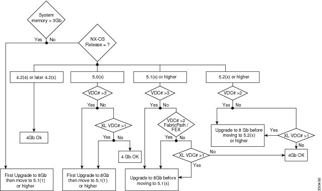
To determine which version of Cisco NX-OS that the switch is running, use the show version command.
Adding 4 GB of Memory to a Supervisor Module
If you need to add 4 GB of memory to the supervisor modules on your switch so that they have 8 GB of memory, the switch must be running NX-OS Release 5.1(1) or later release.
Note![]() If the switch has two supervisor modules, both must have the same amount of memory. If you upgrade the standby supervisor module to 8 GB of memory, you must then switch the active supervisor to standby and upgrade the new standby supervisor to 8 GB of memory.
If the switch has two supervisor modules, both must have the same amount of memory. If you upgrade the standby supervisor module to 8 GB of memory, you must then switch the active supervisor to standby and upgrade the new standby supervisor to 8 GB of memory.
Note![]() If you are using an earlier version of Cisco NX-OS, the supervisor modules can have only 4 GB of memory. If you need to remove 4 GB of memory to have only 4 GB of memory in a supervisor, see the “Removing 4 GB of Memory from a Supervisor Module” section.
If you are using an earlier version of Cisco NX-OS, the supervisor modules can have only 4 GB of memory. If you need to remove 4 GB of memory to have only 4 GB of memory in a supervisor, see the “Removing 4 GB of Memory from a Supervisor Module” section.
To add 4 GB of memory to the supervisor modules, follow these steps:
Step 1![]() Follow ESD procedures, which include wearing an ESD wrist strap and placing antistatic foam or antistatic padding where you will place the supervisor module while working with it.
Follow ESD procedures, which include wearing an ESD wrist strap and placing antistatic foam or antistatic padding where you will place the supervisor module while working with it.
Step 2![]() Disconnect the cables attached to the front of the module to be removed. If there are two supervisors in the switch, disconnect the cables from the standby supervisor.
Disconnect the cables attached to the front of the module to be removed. If there are two supervisors in the switch, disconnect the cables from the standby supervisor.
Note![]() If the chassis has two supervisor modules and you disconnect the active supervisor module, that supervisor goes into standby mode and the other supervisor becomes the active supervisor.
If the chassis has two supervisor modules and you disconnect the active supervisor module, that supervisor goes into standby mode and the other supervisor becomes the active supervisor.
Step 3![]() Loosen and fully unscrew both captive screws on the module.
Loosen and fully unscrew both captive screws on the module.
Step 4![]() Press both ejector release buttons on the ends of the module (see Callout 2 in Figure 10-5) to push out the ejector levers and to disconnect the module.
Press both ejector release buttons on the ends of the module (see Callout 2 in Figure 10-5) to push out the ejector levers and to disconnect the module.
Note![]() If you stop this procedure at this point without removing the module and need to power it up, simultaneously press both ejector levers back to the face of the module until they click, secure both of the module captive screws to the chassis, and then use the no poweroff module slot_number command to power up the module.
If you stop this procedure at this point without removing the module and need to power it up, simultaneously press both ejector levers back to the face of the module until they click, secure both of the module captive screws to the chassis, and then use the no poweroff module slot_number command to power up the module.
Step 5![]() Simultaneously rotate the two ejector levers outward to unseat the module from the midplane connector (see Callout 3 in Figure 10-5).
Simultaneously rotate the two ejector levers outward to unseat the module from the midplane connector (see Callout 3 in Figure 10-5).
Step 6![]() With a hand on each ejector lever, pull the module part way out of its slot in the chassis.
With a hand on each ejector lever, pull the module part way out of its slot in the chassis.
Step 7![]() Grasp the front edge of the module with one hand and place your other hand under the lower side of the module to support its weight. Pull the module out of its slot.
Grasp the front edge of the module with one hand and place your other hand under the lower side of the module to support its weight. Pull the module out of its slot.
Step 8![]() If you are removing the module from a Cisco 7010 chassis, rotate the module 90 degrees counterclockwise so that it is horizontal and you can see the circuitry from above.
If you are removing the module from a Cisco 7010 chassis, rotate the module 90 degrees counterclockwise so that it is horizontal and you can see the circuitry from above.
Step 9![]() On the second memory slot from the front of the module, rotate both spring clips away from the slot (see Callout 1 in Figure 10-9).
On the second memory slot from the front of the module, rotate both spring clips away from the slot (see Callout 1 in Figure 10-9).
Figure 10-9 Adding a 4-GB DIMM
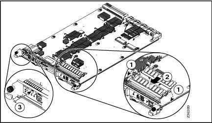
Step 10![]() Holding the edges of the 4-GB memory board with one hand, slide it into the second memory slot from the front of the module until the two spring clips click into the DIMM (see Callout 2 in Figure 10-9).
Holding the edges of the 4-GB memory board with one hand, slide it into the second memory slot from the front of the module until the two spring clips click into the DIMM (see Callout 2 in Figure 10-9).
Step 11![]() Place an 8-GB label on the front of the module and to the right of the N7K-SUP-1 identifier.
Place an 8-GB label on the front of the module and to the right of the N7K-SUP-1 identifier.
Step 12![]() Rotate both ejector levers away from the front of the supervisor module.
Rotate both ejector levers away from the front of the supervisor module.
Step 13![]() Grasp the front of the supervisor module with one hand and place your other hand under the module to support its weight.
Grasp the front of the supervisor module with one hand and place your other hand under the module to support its weight.
Step 14![]() Align the module to the open supervisor slot in the chassis and push the module into the slot until it makes contact with the midplane.
Align the module to the open supervisor slot in the chassis and push the module into the slot until it makes contact with the midplane.
Step 15![]() Simultaneously push both ejector levers inward until they come in contact with the face of the module.
Simultaneously push both ejector levers inward until they come in contact with the face of the module.
The module should be fully seated in the slot and the captive screws should be aligned with their holes in the chassis. The EMI gasket should close the gap between this module and the next module.
Step 16![]() Screw in the two captive screws to the chassis and tighten them to 8 in-lb (0.9 N·m).
Screw in the two captive screws to the chassis and tighten them to 8 in-lb (0.9 N·m).
Step 17![]() Reconnect the console cable to the CONSOLE SERIAL PORT as explained in the “Connecting to the Console” section.
Reconnect the console cable to the CONSOLE SERIAL PORT as explained in the “Connecting to the Console” section.
Step 18![]() If the previous supervisor module was connected to an asynchronous device through a modem, connect the modem cable to the COM1/AUX SERIAL PORT as explained in the “Connecting to the Console” section.
If the previous supervisor module was connected to an asynchronous device through a modem, connect the modem cable to the COM1/AUX SERIAL PORT as explained in the “Connecting to the Console” section.
Step 19![]() Reconnect the network management cable to the MGMT ETH port as explained in the “Setting Up the Management Interface” section.
Reconnect the network management cable to the MGMT ETH port as explained in the “Setting Up the Management Interface” section.
Step 20![]() Reconnect the CMP cable to the CMP MGMT ETH port as explained in the “Connecting the Supervisor CMP Port” section.
Reconnect the CMP cable to the CMP MGMT ETH port as explained in the “Connecting the Supervisor CMP Port” section.
Step 21![]() If you need to upgrade the other supervisor module to 8 GB (both modules must have the same amount of memory), repeat Steps 2 through 19.
If you need to upgrade the other supervisor module to 8 GB (both modules must have the same amount of memory), repeat Steps 2 through 19.
Step 22![]() Verify that the upgraded module has 8 GB of memory. If there are two supervisor modules installed in the switch, use the system switchover command to make that module active, and then use the show system resources command. If there is just one supervisor module installed in the switch, use the show system resources command.
Verify that the upgraded module has 8 GB of memory. If there are two supervisor modules installed in the switch, use the system switchover command to make that module active, and then use the show system resources command. If there is just one supervisor module installed in the switch, use the show system resources command.
Step 23![]() If you need to upgrade another supervisor module to 8 GB (both supervisor modules in a switch with two supervisors must have the same amount of memory), repeat Steps 2 through 22.
If you need to upgrade another supervisor module to 8 GB (both supervisor modules in a switch with two supervisors must have the same amount of memory), repeat Steps 2 through 22.
Removing 4 GB of Memory from a Supervisor Module
If you need to remove 4 GB of memory from the supervisor modules so that they each have only 4 GB of memory, you must remove the DIMM from the second memory slot from the front of each installed supervisor module.
Note![]() If the switch has two supervisor modules, both must have the same amount of memory. If you downgrade one supervisor module to 4 GB of memory, you must also downgrade the other supervisor module to 4 GB of memory.
If the switch has two supervisor modules, both must have the same amount of memory. If you downgrade one supervisor module to 4 GB of memory, you must also downgrade the other supervisor module to 4 GB of memory.
To remove 4 GB of memory from a supervisor module, follow these steps:
Step 1![]() Follow ESD procedures, which include wearing an ESD wrist strap and placing antistatic foam or antistatic padding where you will place the supervisor module while working with it.
Follow ESD procedures, which include wearing an ESD wrist strap and placing antistatic foam or antistatic padding where you will place the supervisor module while working with it.
Step 2![]() Disconnect the cables attached to the front of the module to be removed. If there are two supervisor modules installed in the switch, disconnect the cables from the standby supervisor.
Disconnect the cables attached to the front of the module to be removed. If there are two supervisor modules installed in the switch, disconnect the cables from the standby supervisor.
Note![]() If the chassis has two supervisor modules and you disconnect the active supervisor module, that supervisor goes into standby mode and the other supervisor becomes the active supervisor.
If the chassis has two supervisor modules and you disconnect the active supervisor module, that supervisor goes into standby mode and the other supervisor becomes the active supervisor.
Step 3![]() Loosen and fully unscrew both captive screws on the installed supervisor module that you need to upgrade.
Loosen and fully unscrew both captive screws on the installed supervisor module that you need to upgrade.
Step 4![]() Press both ejector release buttons on the ends of the module (see Callout 2 in Figure 10-5) to push out the ejector levers and to disconnect the module.
Press both ejector release buttons on the ends of the module (see Callout 2 in Figure 10-5) to push out the ejector levers and to disconnect the module.
Note![]() If you stop this procedure at this point without removing the module and need to power it up, simultaneously press both ejector levers back to the face of the module until they click, secure both of the module captive screws to the chassis, and then use the no poweroff module slot_number command to power up the module.
If you stop this procedure at this point without removing the module and need to power it up, simultaneously press both ejector levers back to the face of the module until they click, secure both of the module captive screws to the chassis, and then use the no poweroff module slot_number command to power up the module.
Step 5![]() Simultaneously rotate the two ejector levers outward to unseat the module from the midplane connector (see Callout 3 in Figure 10-5).
Simultaneously rotate the two ejector levers outward to unseat the module from the midplane connector (see Callout 3 in Figure 10-5).
Step 6![]() With a hand on each ejector lever, pull the module part way out of its slot in the chassis.
With a hand on each ejector lever, pull the module part way out of its slot in the chassis.
Step 7![]() Grasp the front edge of the module with one hand and place your other hand under the lower side of the module to support its weight. Pull the module out of its slot.
Grasp the front edge of the module with one hand and place your other hand under the lower side of the module to support its weight. Pull the module out of its slot.
Step 8![]() If you are removing the module from a Cisco 7010 chassis, rotate the module 90 degrees counterclockwise so that it is horizontal and you can see the circuitry from above.
If you are removing the module from a Cisco 7010 chassis, rotate the module 90 degrees counterclockwise so that it is horizontal and you can see the circuitry from above.
Step 9![]() For the DIMM in the second memory slot from the front of the supervisor module, rotate the two spring clips away from the DIMM (see Callout 1 in Figure 10-10).
For the DIMM in the second memory slot from the front of the supervisor module, rotate the two spring clips away from the DIMM (see Callout 1 in Figure 10-10).
Figure 10-10 Removing a 4-GB DIMM
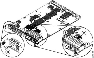
|
|
On the second socket from the front of the module, rotate both spring clips away from the DIMM. |
|
|
|
|
Hold the DIMM by its edges and pull it out of the memory slot. |
|
Step 10![]() Holding the edges of the 4-GB DIMM with your fingers, slide it out of its memory slot (see Callout 2 in Figure 10-10) and place it in an antistatic bag.
Holding the edges of the 4-GB DIMM with your fingers, slide it out of its memory slot (see Callout 2 in Figure 10-10) and place it in an antistatic bag.
Step 11![]() Remove the 8-GB label from the front of the module.
Remove the 8-GB label from the front of the module.
Step 12![]() Rotate both ejector levers away from the front of the supervisor module.
Rotate both ejector levers away from the front of the supervisor module.
Step 13![]() Grasp the front of the module with one hand and place your other hand under the module to support its weight.
Grasp the front of the module with one hand and place your other hand under the module to support its weight.
Step 14![]() Align the module to the open supervisor slot in the chassis and push the module into the slot until it makes contact with the midplane.
Align the module to the open supervisor slot in the chassis and push the module into the slot until it makes contact with the midplane.
Step 15![]() Simultaneously push both ejector levers inward until they come in contact with the face of the module.
Simultaneously push both ejector levers inward until they come in contact with the face of the module.
Step 16![]() The module should be fully seated in the slot and the captive screws should be aligned with their holes in the chassis. The EMI gasket should close the gap between this module and the next module.
The module should be fully seated in the slot and the captive screws should be aligned with their holes in the chassis. The EMI gasket should close the gap between this module and the next module.
Step 17![]() Screw in the two captive screws to the chassis and tighten them to 8 in-lb (0.9 N·m).
Screw in the two captive screws to the chassis and tighten them to 8 in-lb (0.9 N·m).
Step 18![]() Reconnect the console cable to the CONSOLE SERIAL PORT as explained in the “Connecting to the Console” section.
Reconnect the console cable to the CONSOLE SERIAL PORT as explained in the “Connecting to the Console” section.
Step 19![]() If the previous supervisor module was connected to an asynchronous device through a modem, connect the modem cable to the COM1/AUX SERIAL PORT as explained in the “Connecting to the Console” section.
If the previous supervisor module was connected to an asynchronous device through a modem, connect the modem cable to the COM1/AUX SERIAL PORT as explained in the “Connecting to the Console” section.
Step 20![]() Reconnect the network management cable to the MGMT ETH port as explained in the “Setting Up the Management Interface” section.
Reconnect the network management cable to the MGMT ETH port as explained in the “Setting Up the Management Interface” section.
Step 21![]() Reconnect the CMP cable to the CMP MGMT ETH port as explained in the “Connecting the Supervisor CMP Port” section.
Reconnect the CMP cable to the CMP MGMT ETH port as explained in the “Connecting the Supervisor CMP Port” section.
Step 22![]() Verify that the module has 4 GB of memory by using the system switchover command to make the downgraded module active and using the show system resources command.
Verify that the module has 4 GB of memory by using the system switchover command to make the downgraded module active and using the show system resources command.
Step 23![]() If you need to downgrade the other supervisor module to 4 GB (both modules must have the same amount of memory), repeat Steps 2 through 21.
If you need to downgrade the other supervisor module to 4 GB (both modules must have the same amount of memory), repeat Steps 2 through 21.
Step 24![]() Verify that the downgraded module has 4 GB of memory. If there are two supervisor modules installed in the switch, use the system switchover command to make the downgraded module active, and then use the show system resources command. If there is just one supervisor module installed in the switch, use the show system resources command.
Verify that the downgraded module has 4 GB of memory. If there are two supervisor modules installed in the switch, use the system switchover command to make the downgraded module active, and then use the show system resources command. If there is just one supervisor module installed in the switch, use the show system resources command.
Step 25![]() If you need to downgrade another supervisor module to 4 GB (both supervisor modules in a switch with two supervisors must have the same amount of memory), repeat Steps 2 through 24.
If you need to downgrade another supervisor module to 4 GB (both supervisor modules in a switch with two supervisors must have the same amount of memory), repeat Steps 2 through 24.
Installing an I/O Module
A Cisco Nexus 7004 switch has up to two I/O modules, a Cisco Nexus 7009 switch has up to seven I/O modules, a Cisco Nexus 7010 switch has up to eight I/O modules, and a Cisco Nexus 7018 has up to 16 I/O modules. These modules are located on the front of the chassis. You can replace one of these modules at a time while the switch is operating.
Note![]() If you are installing F2 I/O modules, all of the fabric modules in the switch must be Series 2 fabric modules.
If you are installing F2 I/O modules, all of the fabric modules in the switch must be Series 2 fabric modules.
This section describes how to replace I/O modules and includes the following topics:
Required Tools
You need a flat-blade or number 2 Phillips-head screwdriver to loosen or tighten the captive screws on the I/O module.
Installing a New I/O Module
A Cisco Nexus 7000 Series switch includes one or more of the following types of I/O modules:
- 48-port 10/100/1000 Ethernet module (N7K-M148GT-11)
- 48-port 10/100/1000 Ethernet module with XL option (N7K-M148GT-11L)
- 48-port 1-Gigabit Ethernet I/O module (N7K-M148GS-11)
- 48-port 1-Gigabit Ethernet I/O module with XL option (N7K-M148GS-11L)
- 48-port 1-/10-Gigabit Ethernet I/O modules with XL (N7K-F248XP-25 and N7K-F248XP-25E)
- 48-port 1-/10-Gigabit Ethernet I/O module (N7K-F348XP-25)
- 48-port 1-/10-Gigabit Ethernet I/O modules with XL option(N7K-M348XP-25L)
- 24-port 10-Gigabit Ethernet I/O modules with XL option (N7K-M224XP-23L)
- 24-port 40-Gigabit Ethernet I/O modules with XL option(N7K-M324FQ-25L)
- 32-port 10-Gigabit Ethernet I/O module (N7K-M132XP-12)
- 32-port 10-Gigabit Ethernet I/O module with XL option (N7K-M132XP-12L)
- 32-port 1- and 10-Gigabit Ethernet I/O module (N7K-F132XP-15)
- 8-port 10-Gigabit Ethernet I/O module with XL option (N7K-M108X2-12L)
- 12-port 40-Gigabit Ethernet I/O module (N7K-F312FQ-25)
- 6-port 100-Gigabit Ethernet I/O module (N7K-F306CK-25)
You can replace each of these I/O modules with another module of the same type while the Cisco Nexus 7000 Series switch is operational. To do this action, you must first remove an I/O module from the chassis, and then install a new or replacement I/O module in the newly vacated slot within a couple of minutes to maintain the designed airflow.
Note![]() M3-Series I/O modules are not supported on the Cisco Nexus 7004 switch.
M3-Series I/O modules are not supported on the Cisco Nexus 7004 switch.
Note![]() On a Cisco Nexus 7000 Series switch, when a transceiver is removed or inserted on an interface in a VDC (for example VDC-1), a trap is sent to all the VDCs in the switch (including the VDC-1). This behavior is applicable for module removal or insertion and to other physical entity events.
On a Cisco Nexus 7000 Series switch, when a transceiver is removed or inserted on an interface in a VDC (for example VDC-1), a trap is sent to all the VDCs in the switch (including the VDC-1). This behavior is applicable for module removal or insertion and to other physical entity events.
Warning![]() Hazardous voltage or energy is present on the backplane when the system is operating. Use caution when servicing. Statement 1034
Hazardous voltage or energy is present on the backplane when the system is operating. Use caution when servicing. Statement 1034
To replace an I/O module, follow these steps:
Step 1![]() Place antistatic mats or antistatic foam where you can place the old and new I/O modules. Choose a place that prevents damage to the module while it is outside the chassis.
Place antistatic mats or antistatic foam where you can place the old and new I/O modules. Choose a place that prevents damage to the module while it is outside the chassis.
Step 2![]() Unpack and place the replacement I/O module on an antistatic mat or antistatic foam.
Unpack and place the replacement I/O module on an antistatic mat or antistatic foam.
Step 3![]() Disconnect each I/O cable from the front of the module by doing the following:
Disconnect each I/O cable from the front of the module by doing the following:
- For the 48-port 10/100/1000 Ethernet I/O module (N7K-M148GT-11 and N7K-M148GT-11L), unplug each cable.
- For the 48-port 1-Gigabit Ethernet types of I/O modules (N7K-M148GS-11 and N7K-M148GS-11L) and the 48-port 1- and 10-Gigabit Ethernet I/O module (N7K-F248XP-25), remove the fiber-optic cables and then remove the SFP transceivers.
- For the 48-port 1- and 10-Gigabit Ethernet I/O module (N7K-F348XP-25), remove the fiber-optic cables and then remove the SFP/SFP+ transceivers.
- For the 48-port 1- and 10-Gigabit Ethernet types of I/O module (N7K-M348XP-25L), remove the fiber-optic cables and then remove the SFP+ transceivers.
- For the 32-port 10-Gigabit Ethernet types of I/O modules (N7K-M132XP-12, N7K-M132XP-12L, and N7K-F132XP-15), remove the fiber-optic cables and then remove the SFP+ transceivers.
- For the 24-port 40-Gigabit Ethernet types of I/O modules (N7K-M324FQ-25L), remove the fiber-optic cables and then remove the QSFP transceivers.
- For the 12-port 40-Gigabit Ethernet I/O modules (N7K-F312FQ-25), remove the fiber-optic cables and then remove the QSFP+ transceivers.
- For the 8-port 10-Gigabit Ethernet I/O module (N7K-M108X2-12L), remove the fiber-optic cables and then remove the X2 transceivers.
- For the 6-port 100-Gigabit Ethernet I/O module (N7K-F306CK-25), remove the fiber-optic cables and then remove the CPAK transceivers.
Note![]() To prevent contaminants from entering the fiber-optic lines or transceivers, cover the fiber-optic openings with a plug.
To prevent contaminants from entering the fiber-optic lines or transceivers, cover the fiber-optic openings with a plug.
Warning![]() Invisible laser radiation may be omitted from disconnected fibers or connectors. Do not stare into beams or view directly with optical instruments. Statement 1051
Invisible laser radiation may be omitted from disconnected fibers or connectors. Do not stare into beams or view directly with optical instruments. Statement 1051
Step 4![]() Loosen the two captive screws identified in View A of Figure 10-11.
Loosen the two captive screws identified in View A of Figure 10-11.
Figure 10-11 Unseating an I/O Module
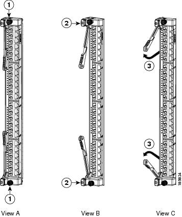
|
|
|
Simultaneously swing open both ejector levers to unseat the module. |
|
|
|
|
Step 5![]() Press ejector release buttons on the top and bottom ends of the module (see View B in Figure 10-11) to push out the ejector levers and to disconnect the module.
Press ejector release buttons on the top and bottom ends of the module (see View B in Figure 10-11) to push out the ejector levers and to disconnect the module.
Step 6![]() Simultaneously rotate the two ejector levers outward to unseat the module from the midplane connector (see View C in Figure 10-11).
Simultaneously rotate the two ejector levers outward to unseat the module from the midplane connector (see View C in Figure 10-11).
Step 7![]() With a hand on each ejector, pull the module part way out of its slot in the chassis.
With a hand on each ejector, pull the module part way out of its slot in the chassis.
Step 8![]() Grasp the front edge of the module and place your other hand under the module to support its weight. Pull the module out of its slot. Do not touch the module circuitry.
Grasp the front edge of the module and place your other hand under the module to support its weight. Pull the module out of its slot. Do not touch the module circuitry.
Step 9![]() If you are removing the module from a Cisco Nexus 7010 chassis, rotate the module 90 degrees counterclockwise so that it is horizontal (with the circuitry seen from above).
If you are removing the module from a Cisco Nexus 7010 chassis, rotate the module 90 degrees counterclockwise so that it is horizontal (with the circuitry seen from above).
Step 10![]() Place the module on an antistatic mat or repack it in its original packing materials as shown in Figure 10-12 (8- and 48-port types of I/O modules) or Figure 10-13 (32-port types of I/O modules).
Place the module on an antistatic mat or repack it in its original packing materials as shown in Figure 10-12 (8- and 48-port types of I/O modules) or Figure 10-13 (32-port types of I/O modules).
Figure 10-12 Repacking an 8- or 48-Port I/O Module (N7K-M108X2-12L, N7K-M148GT-11, N7K-M148GT-11L, N7K-M148GS-11, or N7K-M148GS-11L)
|
|
|
||
|
|
|
||
|
|
|
||
|
|
|
||
|
|
Fold the long flaps up along the ends of the module and then over the top of the module. Insert the two tabs on each flap into the side flaps. |
|
|
|
|
|
Figure 10-13 Repacking a 32-port Type of I/O Module (N7K-F132XP-15, N7K-M132XP-12, or N7K-M132XP-12L)
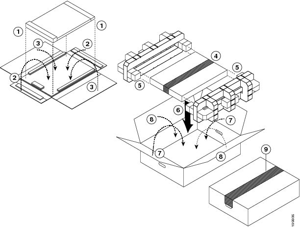
Step 11![]() On the replacement I/O module, rotate both ejector levers fully away from the front of the module.
On the replacement I/O module, rotate both ejector levers fully away from the front of the module.
Step 12![]() If you are inserting the module into a Cisco Nexus 7010 chassis, rotate the module 90 degrees clockwise.
If you are inserting the module into a Cisco Nexus 7010 chassis, rotate the module 90 degrees clockwise.
Step 13![]() Align the module to the chassis guides for the vacated slot, and slide the module part way into the slot.
Align the module to the chassis guides for the vacated slot, and slide the module part way into the slot.
Step 14![]() With one or both hands on the front of the module, push the module all the way into the slot until it seats on the midplane connector.
With one or both hands on the front of the module, push the module all the way into the slot until it seats on the midplane connector.
Step 15![]() Simultaneously push both ejector levers inward until they come in contact with the face of the module.
Simultaneously push both ejector levers inward until they come in contact with the face of the module.
Note![]() Verify that the ejector levers are fully closed before tightening the captive screws. Failure to fully seat the module in the backplane connector can result in error messages.
Verify that the ejector levers are fully closed before tightening the captive screws. Failure to fully seat the module in the backplane connector can result in error messages.
Step 16![]() Tighten the two captive screws on the I/O module to 8 in-lb (0.9 N·m).
Tighten the two captive screws on the I/O module to 8 in-lb (0.9 N·m).
Step 17![]() Reconnect the I/O cables to the ports or the transceivers on the fiber-optic cables to the ports on the module.
Reconnect the I/O cables to the ports or the transceivers on the fiber-optic cables to the ports on the module.
Installing a NAM Module
The Network Analysis Module (NAM) can be installed in an I/O module slot on the Cisco Nexus 7004, 7009, 7010, or 7018 switch chassis. You can either replace a NAM or install a new one in an empty I/O module slot. If you install a new module, you must also install and configure the latest NAM software on the module.
Note![]() If the switch shipped with one or more NAM modules already installed, then the modules are already configured with the Prime NAM software and are ready to be used. If you are installing a new NAM module and the module does not automatically boot up, then you must install and configure the Prime NAM software in order to use the module.
If the switch shipped with one or more NAM modules already installed, then the modules are already configured with the Prime NAM software and are ready to be used. If you are installing a new NAM module and the module does not automatically boot up, then you must install and configure the Prime NAM software in order to use the module.
This section describes how to install NAM modules and includes the following topics:
- Required Tools for Installing a NAM
- Installing or Replacing a NAM
- Installing the Cisco Prime NAM Software
- Configuring the NAM
- Upgrading the Cisco Prime NAM software
Required Tools for Installing a NAM
You need a flat-blade or number 2 Phillips-head screwdriver to loosen or tighten the captive screws on the I/O module.
Installing or Replacing a NAM
A Cisco Nexus 7004, 7009, 7010, or 7018 switch can have one or more NAMs installed in it. You can either install a new one in an empty I/O module slot or replace an existing NAM or I/O module. If you are replacing an existing NAM, you must first shut down the module with the out-of-service module command before removing the original module. If you are replacing an I/O module, you can either use the out-of-service module command to shut the module down or just remove the module and a graceful shutdown will automatically occur.
Warning![]() Hazardous voltage or energy is present on the backplane when the system is operating. Use caution when servicing. Statement 1034
Hazardous voltage or energy is present on the backplane when the system is operating. Use caution when servicing. Statement 1034
To install or replace a NAM, follow these steps:
Step 1![]() Place antistatic mats or antistatic foam where you can place the old and new I/O modules. Choose a place that prevents damage to the module while it is outside the chassis.
Place antistatic mats or antistatic foam where you can place the old and new I/O modules. Choose a place that prevents damage to the module while it is outside the chassis.
Step 2![]() Unpack and place the new I/O module on an antistatic mat or antistatic foam.
Unpack and place the new I/O module on an antistatic mat or antistatic foam.
Step 3![]() If you are installing a new NAM in an empty slot, remove the blank filler plate that is in the slot by unscrewing its captive screws and pulling the plate off the chassis. Go to Step 5 to continue the installation.
If you are installing a new NAM in an empty slot, remove the blank filler plate that is in the slot by unscrewing its captive screws and pulling the plate off the chassis. Go to Step 5 to continue the installation.
Step 4![]() To remove an existing NAM, follow these steps:
To remove an existing NAM, follow these steps:
a.![]() Shut down the module by using the out-of-service module command with the NX-OS CLI.
Shut down the module by using the out-of-service module command with the NX-OS CLI.
Note![]() Alternatively, you can use the poweroff module command, but that command requires that you use the no poweroff module command after reinstalling the module. If you use the out-of-service module command, you do not need to use another command to bring the module up when you install it.
Alternatively, you can use the poweroff module command, but that command requires that you use the no poweroff module command after reinstalling the module. If you use the out-of-service module command, you do not need to use another command to bring the module up when you install it.
b.![]() Disconnect any cables attached to the front of the module.
Disconnect any cables attached to the front of the module.
c.![]() Loosen the two captive screws (one on each end of the module) until they are no longer in contact with the chassis.
Loosen the two captive screws (one on each end of the module) until they are no longer in contact with the chassis.
d.![]() Press ejector release buttons on each end of the module to push out the ejector levers.
Press ejector release buttons on each end of the module to push out the ejector levers.
e.![]() Simultaneously rotate the two ejector levers outward to unseat the module from the midplane connector.
Simultaneously rotate the two ejector levers outward to unseat the module from the midplane connector.
f.![]() With a hand on each ejector, pull the module part way out of its slot in the chassis.
With a hand on each ejector, pull the module part way out of its slot in the chassis.
g.![]() Grasp the front edge of the module and place your other hand under the module to support its weight. Pull the module out of its slot. Do not touch the module circuitry.
Grasp the front edge of the module and place your other hand under the module to support its weight. Pull the module out of its slot. Do not touch the module circuitry.
h.![]() If you are removing the module from a Cisco Nexus 7010 chassis, rotate the module 90 degrees counterclockwise so that it is horizontal (with the electronics seen from above).
If you are removing the module from a Cisco Nexus 7010 chassis, rotate the module 90 degrees counterclockwise so that it is horizontal (with the electronics seen from above).
i.![]() Place the module on an antistatic mat or repack it in its original packing materials.
Place the module on an antistatic mat or repack it in its original packing materials.
Step 5![]() Install the new NAM as follows:
Install the new NAM as follows:
a.![]() On the replacement NAM, rotate both ejector levers fully away from the front of the module. If necessary, press the two ejector buttons to release the levers from the front of the module and then rotate the levers away from the front of the module.
On the replacement NAM, rotate both ejector levers fully away from the front of the module. If necessary, press the two ejector buttons to release the levers from the front of the module and then rotate the levers away from the front of the module.
b.![]() If you are inserting the module into a Cisco Nexus 7010 chassis, rotate the module 90 degrees clockwise so that the circuitry is seen from the right side.
If you are inserting the module into a Cisco Nexus 7010 chassis, rotate the module 90 degrees clockwise so that the circuitry is seen from the right side.
c.![]() Align the module to the chassis guides for the open slot, and slide the module into the slot until it stops with the front of the module being about 1/4 inch (0.6 cm) out from the front of the chassis.
Align the module to the chassis guides for the open slot, and slide the module into the slot until it stops with the front of the module being about 1/4 inch (0.6 cm) out from the front of the chassis.
d.![]() Simultaneously push both ejector levers inward until they come in contact with the face of the module. The module moves completely into the slot with the front of the module being at the front of the chassis.
Simultaneously push both ejector levers inward until they come in contact with the face of the module. The module moves completely into the slot with the front of the module being at the front of the chassis.
e.![]() Verify that the ejector levers are fully closed before tightening the captive screws. Failure to fully seat the module in the midplane connectors can result in error messages or damage to the module.
Verify that the ejector levers are fully closed before tightening the captive screws. Failure to fully seat the module in the midplane connectors can result in error messages or damage to the module.
f.![]() Tighten the two captive screws on the I/O module to 8 in-lb (0.9 N·m) of torque.
Tighten the two captive screws on the I/O module to 8 in-lb (0.9 N·m) of torque.
g.![]() If you disconnected any cables from the front of the module, reconnect those cables to the module.
If you disconnected any cables from the front of the module, reconnect those cables to the module.
h.![]() Verify that the STATUS LED eventurally turns green to show that the module is operational. For information on the other states indicated by this LED, see the “NAM-NX1 Module LEDs” section.
Verify that the STATUS LED eventurally turns green to show that the module is operational. For information on the other states indicated by this LED, see the “NAM-NX1 Module LEDs” section.
You are ready to install the Prime NAM software on the new module.
Installing the Cisco Prime NAM Software
To install the Cisco Prime NAM software, follow these steps:
Step 1![]() Use a browser to go to http://software.cisco.com/download/navigator.html.
Use a browser to go to http://software.cisco.com/download/navigator.html.
The Software Download page opens.
Step 2![]() Choose Cloud and Systems Management > Network Analysis Module (NAM) Products > Cisco Prime Network Analysis Module Software > Cisco Prime Network Analysis Module Software 6.2 (or later verssion). A list of software files appears.
Choose Cloud and Systems Management > Network Analysis Module (NAM) Products > Cisco Prime Network Analysis Module Software > Cisco Prime Network Analysis Module Software 6.2 (or later verssion). A list of software files appears.
Step 3![]() Click the Download button for the software file name beginning with nam-nx1. The filename is nam-nx1. x-x-x.bin.gz (where x-x-x is the NAM software release number).
Click the Download button for the software file name beginning with nam-nx1. The filename is nam-nx1. x-x-x.bin.gz (where x-x-x is the NAM software release number).
Step 4![]() Using the NAM CLI, enter the upgrade command to specify the user, password, server,path to the file, and installation file name. For example, for the admin user, “secret” password, server IP address 10.10.10.10, archive/nam_software path, and nam-nx1.6.0.1.bin.gz installation file, you would use the upgrade command as follows:
Using the NAM CLI, enter the upgrade command to specify the user, password, server,path to the file, and installation file name. For example, for the admin user, “secret” password, server IP address 10.10.10.10, archive/nam_software path, and nam-nx1.6.0.1.bin.gz installation file, you would use the upgrade command as follows:
Configuring the NAM
To configure the NAM software, you must do all of the following:
- Configure the VLAN management port from the switch (see the “Configuring a VLAN Management Port for the NAM” section).
- Configure the SPAN session from the switch (see the “Configuring a SPAN Session for a Data Port” section).
- Set up the NAM network configuration for the NAM (see the “Specifying the NAM IP Configuration and Enabling the Web Server” section).
Configuring a VLAN Management Port for the NAM
Using the virtual device context (VDC) that the NAM belongs to, you must configure a VLAN for NAM management traffic, and you must assign that VLAN to the NAM management port.
To configure and assign a VLAN management port, follow these steps:
Step 1![]() Verify that the NAM is active.
Verify that the NAM is active.
Step 2![]() Allocate the NAM interfaces to the VDC as follows:
Allocate the NAM interfaces to the VDC as follows:
- If you are using the default VDC configuration, the NAM interfaces should be allocated to the default VDC automatically. Verify that allocation.
Step 3![]() If a VLAN does not already exist for the NAM, create the VLAN.
If a VLAN does not already exist for the NAM, create the VLAN.
Step 4![]() Add the VLAN to the external interface that will be used to access the NAM by specifying the interface.
Add the VLAN to the external interface that will be used to access the NAM by specifying the interface.
Step 5![]() Assign the VLAN to the management port for the NAM module by using the analysis module command.
Assign the VLAN to the management port for the NAM module by using the analysis module command.
After you have configured a VLAN management port for the NAM, you need to set up a SPAN session to define the switch as the traffic source and the NAM as the traffic destination. You can set up a SPAN session in either one of following ways:
Configuring a SPAN Session for a Data Port
To use the NAM with a switch, you must define a SPAN session between the switch and the NAM. You can specify the switch by its interface and specify the NAM by its data port.
If you need to define the NAM by the port channel used, see the “Configuring a SPAN Session for a Port Channel” section.
SUMMARY STEPS
3.![]() switch_ip_address int interface
switch_ip_address int interface
4.![]() nam_ip_address analysis-module slot_number data-port port_number
nam_ip_address analysis-module slot_number data-port port_number
DETAILED STEPS
Configuring a SPAN Session for a Port Channel
To use the NAM with a switch, you must define a SPAN session between the switch and the NAM. You can specify the switch by its interface IP address and you can specify the NAM by the port channel that it uses.
If you need to define the NAM by its data port, see the “Configuring a SPAN Session for a Data Port” section.
SUMMARY STEPS:
3.![]() switch_ip_address int interface
switch_ip_address int interface
4.![]() nam_ip_address interface port-channel port-channel_number
nam_ip_address interface port-channel port-channel_number
DETAILED STEPS
Specifying the NAM IP Configuration and Enabling the Web Server
After you assign the NAM to a VDC and set up a SPAN session between the switch and the NAM, you must go to the VDC for the NAM, set up the IP configuration for the NAM, and enable the web server. You can enable the NAM to function as either an HTTP server or an HTTPS secure server, but not both simultaneously. After you enable the web server, the NAM is functional.
Step 1![]() Use the Cisco NX-OS attach module slot_number processor number command to open a span session.
Use the Cisco NX-OS attach module slot_number processor number command to open a span session.
Tip![]() Ensure that you are in the correct VDC. To switch to another VDC, you can use the switchto vdc command.
Ensure that you are in the correct VDC. To switch to another VDC, you can use the switchto vdc command.
If you have not changed your password, you will be prompted to enter a new password.
Step 2![]() If you need to enter a new password, enter the password twice.
If you need to enter a new password, enter the password twice.
Please enter a new password:
Confirm new password:
Successfully changed password for user ‘root’
Step 3![]() Enable either an HTTP or HTTPS server.
Enable either an HTTP or HTTPS server.
Step 4![]() Enter the web admin username and password.
Enter the web admin username and password.
Tip![]() We recommend that you change the admin password. All default passwords should be changed as soon as possible.
We recommend that you change the admin password. All default passwords should be changed as soon as possible.
Step 5![]() If you need to use a Telnet or SSH client, do one of the following:
If you need to use a Telnet or SSH client, do one of the following:
Step 6![]() Verify network connectivity to an known IP address by using the ping ip_address command.
Verify network connectivity to an known IP address by using the ping ip_address command.
Step 7![]() Use an approved Firefox or Internet Explorer browser to access the NAM and confirm connectivity. For a list of approved browsers, see the Cisco Prime NAM Release Notes.
Use an approved Firefox or Internet Explorer browser to access the NAM and confirm connectivity. For a list of approved browsers, see the Cisco Prime NAM Release Notes.
If the Cisco Prime NAM web server is properly configured, you can access the NAM login window.
At this point, the only user able to log into the NAM web server is the administrative user that you configured when you enabled the web server. There is no secondary user option. To configure additional users, see the Prime NAM Command Reference Guide or the Prime NAM User Guide on Cisco.com.
Upgrading the Cisco Prime NAM software
If you need the latest version of the Cisco Prime NAM software, see the “Installing the Cisco Prime NAM Software” section.
Replacing a Cisco Nexus 7009 Fabric Module During Operations
The Cisco Nexus 7009 switch has up five fabric modules located on the front of the chassis. You can replace one of these fabric modules at a time while the switch is operating.
You should replace a fabric module with another fabric module within a couple minutes to maintain the designed system airflow. If you cannot replace the fabric module, you must fill the slot with a blank module.
Warning![]() Hazardous voltage or energy is present on the backplane when the system is operating. Use caution when servicing. Statement 1034
Hazardous voltage or energy is present on the backplane when the system is operating. Use caution when servicing. Statement 1034
To replace a fabric module, follow these steps:
Step 1![]() Place an antistatic mat or antistatic foam where you can place the fabric modules. Choose a place that prevents damage to the module while it is outside the chassis.
Place an antistatic mat or antistatic foam where you can place the fabric modules. Choose a place that prevents damage to the module while it is outside the chassis.
Step 2![]() Unpack and place the replacement fabric module on the antistatic mat or antistatic foam.
Unpack and place the replacement fabric module on the antistatic mat or antistatic foam.
Step 3![]() Slide the eject button cover up and press the eject button. The ejector lever will pop out from the front of the fabric module.
Slide the eject button cover up and press the eject button. The ejector lever will pop out from the front of the fabric module.
Step 4![]() Rotate the ejector lever away from the front of the module and pull the module part way from the chassis.
Rotate the ejector lever away from the front of the module and pull the module part way from the chassis.
Step 5![]() Place your other hand under the module, fully pull the module from the chassis, and place the module on an antistatic surface.
Place your other hand under the module, fully pull the module from the chassis, and place the module on an antistatic surface.
Step 6![]() On the replacement module, if the ejector lever is placed against the front of the module, slide the eject button cover up, press the eject button, and fully rotate the ejector lever away from the front of the module.
On the replacement module, if the ejector lever is placed against the front of the module, slide the eject button cover up, press the eject button, and fully rotate the ejector lever away from the front of the module.
Step 7![]() Pick up the module with one hand under the module and the other holding the front of the module.
Pick up the module with one hand under the module and the other holding the front of the module.
Step 8![]() Align the replacement module to the open fabric slot and slide the module all the way into the slot until it comes into contact with the back plane.
Align the replacement module to the open fabric slot and slide the module all the way into the slot until it comes into contact with the back plane.
Step 9![]() Rotate the ejector lever to the front of the module. The module is fully seated in the slot if the front of the module is flush with the front of the other modules in the chassis.
Rotate the ejector lever to the front of the module. The module is fully seated in the slot if the front of the module is flush with the front of the other modules in the chassis.
Replacing or Upgrading a Cisco Nexus 7010 or 7018 Fabric Module During Operations
The Cisco Nexus 7010 and 7018 switches have up to five fabric modules located on the back of the chassis. You can replace one of these fabric modules at a time while the switch is operating. You can also upgrade all of the Fabric 1 modules with Fabric 2 modules, which provide increased performance (when all of the operational fabric modules are Fabric 2 modules) and are recommended for F2 I/O modules.
This section describes how to replace fabric modules and includes the following topics:
- Required Tools
- Replacing a Cisco Nexus 7010 or 7018 Fabric Module
- Upgrading Fabric 1 Modules with Fabric 2 Modules
Required Tools
You need a flat-blade or number 2 Phillips-head screwdriver to loosen or tighten the captive screws on the fan tray.
Replacing a Cisco Nexus 7010 or 7018 Fabric Module
You should replace a fabric module with another fabric module within a couple of minutes to maintain the designed system airflow. If you cannot replace the fabric module, you must fill the slot with a blank module. If you are replacing Fabric 1 modules with Fabric 2 modules, see the “Upgrading Fabric 1 Modules with Fabric 2 Modules” section.
Warning![]() Hazardous voltage or energy is present on the backplane when the system is operating. Use caution when servicing. Statement 1034
Hazardous voltage or energy is present on the backplane when the system is operating. Use caution when servicing. Statement 1034
To replace a fabric module, follow these steps:
Step 1![]() Place an antistatic mat or antistatic foam where you can place the fabric modules. Choose a place that prevents damage to the module while it is outside the chassis.
Place an antistatic mat or antistatic foam where you can place the fabric modules. Choose a place that prevents damage to the module while it is outside the chassis.
Step 2![]() Unpack and place the replacement fabric module on the antistatic mat or antistatic foam.
Unpack and place the replacement fabric module on the antistatic mat or antistatic foam.
Step 3![]() Loosen the two captive screws on the module that you are removing (see View A in Figure 10-14).
Loosen the two captive screws on the module that you are removing (see View A in Figure 10-14).
Figure 10-14 Unseating a Fabric Module
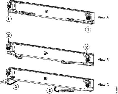
|
|
|
Simultaneously rotate out both ejectors away from the face of the module. |
|
|
|
|
Step 4![]() Press both ejector release buttons to release the ejector levers (see View B in Figure 10-14).
Press both ejector release buttons to release the ejector levers (see View B in Figure 10-14).
Step 5![]() Simultaneously rotate both ejectors away from the face of the module to unseat the module from the midplane connector (see View C in Figure 10-14).
Simultaneously rotate both ejectors away from the face of the module to unseat the module from the midplane connector (see View C in Figure 10-14).
Step 6![]() Holding each ejector lever, pull the module part way out of its slot.
Holding each ejector lever, pull the module part way out of its slot.
Step 7![]() Grasp the front edge of the module and place your other hand under the module to support its weight. Pull the module out of its slot. Do not touch the module circuitry.
Grasp the front edge of the module and place your other hand under the module to support its weight. Pull the module out of its slot. Do not touch the module circuitry.
Step 8![]() If you are removing the module from a Cisco Nexus 7010 chassis. turn the module counterclockwise so that it is horizontal.
If you are removing the module from a Cisco Nexus 7010 chassis. turn the module counterclockwise so that it is horizontal.
Step 9![]() Place the module on the antistatic mat or repack it in its original packing materials. If you are packing a Cisco Nexus 7010 fabric module (N7K-C7010-FAB-1), see Figure 10-15. If you are packing a Cisco Nexus 7018 fabric module (N7K-C7018-FAB-1), see Figure 10-16.
Place the module on the antistatic mat or repack it in its original packing materials. If you are packing a Cisco Nexus 7010 fabric module (N7K-C7010-FAB-1), see Figure 10-15. If you are packing a Cisco Nexus 7018 fabric module (N7K-C7018-FAB-1), see Figure 10-16.
Figure 10-15 Packing a Cisco Nexus 7010 Fabric Module (N7K-C7010-FAB-1)
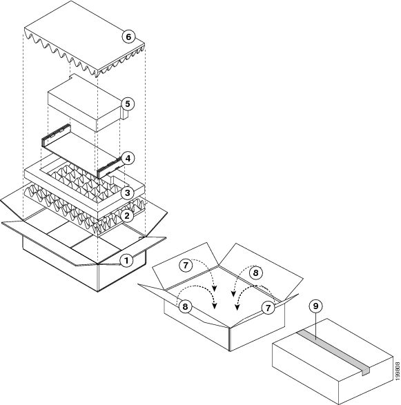
Figure 10-16 Packing a Cisco Nexus 7018 Fabric Module (N7K-C7018-FAB-1)
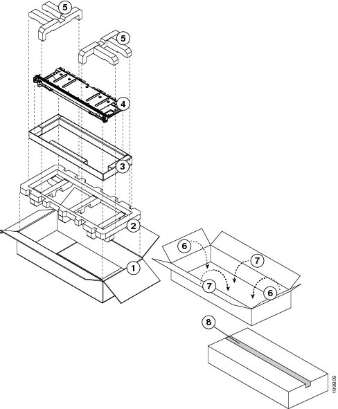
Step 10![]() On the replacement module, rotate the two ejector levers fully away from the face of the module.
On the replacement module, rotate the two ejector levers fully away from the face of the module.
Step 11![]() If you are inserting the module into a Cisco Nexus 7010 chassis, turn the module 90 degrees clockwise.
If you are inserting the module into a Cisco Nexus 7010 chassis, turn the module 90 degrees clockwise.
Step 12![]() With one hand holding each side of the module, align the backside of the module to the slot guides in the vacated slot, and slide the module part way into the slot.
With one hand holding each side of the module, align the backside of the module to the slot guides in the vacated slot, and slide the module part way into the slot.
Step 13![]() With one or both hands on the face of the module, push the module all the way into the slot until it seats on the midplane connector. The EMI gasket will close the gap between this module and any module or chassis edge that is immediately above the module that you just installed.
With one or both hands on the face of the module, push the module all the way into the slot until it seats on the midplane connector. The EMI gasket will close the gap between this module and any module or chassis edge that is immediately above the module that you just installed.
Step 14![]() Simultaneously push both ejector levers inward until they come in contact with the face of the module. The captive screws should be aligned to their holes in the chassis.
Simultaneously push both ejector levers inward until they come in contact with the face of the module. The captive screws should be aligned to their holes in the chassis.
Step 15![]() Tighten the two captive screws on the fabric module to 8 in-lb (0.9 N·m).
Tighten the two captive screws on the fabric module to 8 in-lb (0.9 N·m).
Step 16![]() Verify that the module Status LED is on and becomes green after the module is initialized. To see the different statuses indicated by this LED, see Table D-5.
Verify that the module Status LED is on and becomes green after the module is initialized. To see the different statuses indicated by this LED, see Table D-5.
Upgrading Fabric 1 Modules with Fabric 2 Modules
If you are running Cisco NX-OS 6.0(x) or a later release, you can upgrade all of the Fabric 1 modules with Fabric 2 modules in a Cisco Nexus 7010 or 7018 switch (the Cisco Nexus 7009 uses only Fabric 2 modules). You can upgrade the modules during operations if you replace each within a couple of minutes so that the switch can maintain its designed airflow. The upgrade process is non disruptive to switch operations if there is at least one fabric module installed and operating in the switch while you upgrade another fabric module.
When upgrading fabric modules, you must replace all of the Fabric 1 modules in the switch with Fabric 2 modules within 12 hours or you will see a syslog message that reminds you to complete the upgrade.
Note![]() If you power up a switch that has both types of fabric modules installed, only the Fabric 2 modules power up. If you need the Fabric 1 modules to power up, you must first power off all of the Fabric 2 modules (see the “Shutting Down a Fabric Module” section) before the Fabric 1 modules can power up.
If you power up a switch that has both types of fabric modules installed, only the Fabric 2 modules power up. If you need the Fabric 1 modules to power up, you must first power off all of the Fabric 2 modules (see the “Shutting Down a Fabric Module” section) before the Fabric 1 modules can power up.
Warning![]() Hazardous voltage or energy is present on the backplane when the system is operating. Use caution when servicing. Statement 1034
Hazardous voltage or energy is present on the backplane when the system is operating. Use caution when servicing. Statement 1034
To upgrade Fabric 1 modules with Fabric 2 modules, follow these steps:
Step 1![]() Verify that the switch is running Cisco NX-OS Release 6.0(1) or a later release. If not, you must install Cisco NX-OS Release 6.0(1) or a later release.
Verify that the switch is running Cisco NX-OS Release 6.0(1) or a later release. If not, you must install Cisco NX-OS Release 6.0(1) or a later release.
Step 2![]() Replace the Fabric 1 module that is in the lowest numbered fabric slot as explained in the “Replacing a Cisco Nexus 7010 or 7018 Fabric Module” section.
Replace the Fabric 1 module that is in the lowest numbered fabric slot as explained in the “Replacing a Cisco Nexus 7010 or 7018 Fabric Module” section.
Step 3![]() Enter the show module xbar command, as shown in Example 10-2, to display the types of fabric modules installed in the fabric slots.
Enter the show module xbar command, as shown in Example 10-2, to display the types of fabric modules installed in the fabric slots.
Example 10-2 Listing the Fabric Module Types Installed in the Switch
Step 4![]() If one or more of the fabric modules is indicated as “Fabric Module 1,” repeat Steps 2 and 3 to replace that module with a Fabric 2 module.
If one or more of the fabric modules is indicated as “Fabric Module 1,” repeat Steps 2 and 3 to replace that module with a Fabric 2 module.
If you have replaced all of the Fabric 1 modules with Fabric 2 modules, you can then install F2 I/O modules (see the “Installing an I/O Module” section).
Replacing the Cisco Nexus 7004 Fan Tray During Operations
The Cisco Nexus 7004 switch has one fan tray (part number N7K-C7004-FAN) that is located on the front of the chassis.
Warning![]() Hazardous voltage or energy is present on the backplane when the system is operating. Use caution when servicing. Statement 1034
Hazardous voltage or energy is present on the backplane when the system is operating. Use caution when servicing. Statement 1034
The Cisco Nexus 7004 fan tray is designed to be removed and replaced during operations, but you should replace the fan tray within a couple of minutes to maintain the designed system airflow.
Warning![]() When removing the fan tray, keep your hands and fingers away from the spinning fan blades. Let the fan blades completely stop before you remove the fan tray. Statement 258
When removing the fan tray, keep your hands and fingers away from the spinning fan blades. Let the fan blades completely stop before you remove the fan tray. Statement 258
To replace a Cisco Nexus 7004 fan tray, follow these steps:
Step 1![]() Place an antistatic mat or antistatic foam where you can place two fan trays (the new fan tray and the one that you will remove from the switch).
Place an antistatic mat or antistatic foam where you can place two fan trays (the new fan tray and the one that you will remove from the switch).
Choose a place that prevents damage to the fan trays while they are outside the chassis.
Step 2![]() Unpack and place the replacement fan tray on the antistatic mat or antistatic foam. Keep the shipping materials for the fan tray that you are removing.
Unpack and place the replacement fan tray on the antistatic mat or antistatic foam. Keep the shipping materials for the fan tray that you are removing.
Step 3![]() Unscrew the two captive screws on the front of the fan tray until they spring out from the fan tray.
Unscrew the two captive screws on the front of the fan tray until they spring out from the fan tray.
Step 4![]() Grab the fan tray handle with one hand and pull the fan tray part way out of the chassis.
Grab the fan tray handle with one hand and pull the fan tray part way out of the chassis.
Step 5![]() Place your other hand under the fan tray to support its weight, pull the fan tray out of the chassis, and place it on the antistatic pad or repack it in the shipping materials.
Place your other hand under the fan tray to support its weight, pull the fan tray out of the chassis, and place it on the antistatic pad or repack it in the shipping materials.
Step 6![]() Grab the handle of the replacement power supply with one hand, place your other hand under the fan tray, and align the fan tray to the fan tray bay in the chassis.
Grab the handle of the replacement power supply with one hand, place your other hand under the fan tray, and align the fan tray to the fan tray bay in the chassis.
Step 7![]() Push the fan tray all the way into the chassis until its front touches the front of the chassis.
Push the fan tray all the way into the chassis until its front touches the front of the chassis.
Step 8![]() Screw in the two captive screws.
Screw in the two captive screws.
Step 9![]() Make sure that the STATUS LED turns on and is green.
Make sure that the STATUS LED turns on and is green.
Replacing a Cisco Nexus 7009 Fan Tray During Operations
The Cisco Nexus 7009 switch has one fan tray (part number N7K-C7009-FAN) that is located on the backside of the chassis.
Warning![]() Hazardous voltage or energy is present on the backplane when the system is operating. Use caution when servicing. Statement 1034
Hazardous voltage or energy is present on the backplane when the system is operating. Use caution when servicing. Statement 1034
The Cisco Nexus 7009 fan tray is designed to be removed and replaced during operations, but you should replace the fan tray within a couple of minutes to maintain the designed system airflow.
Warning![]() When removing the fan tray, keep your hands and fingers away from the spinning fan blades. Let the fan blades completely stop before you remove the fan tray. Statement 258
When removing the fan tray, keep your hands and fingers away from the spinning fan blades. Let the fan blades completely stop before you remove the fan tray. Statement 258
To replace a Cisco Nexus 7009 fan tray, follow these steps:
Step 1![]() Place an antistatic mat or antistatic foam where you can place two fan trays (the new fan tray and the one that you will remove from the switch).
Place an antistatic mat or antistatic foam where you can place two fan trays (the new fan tray and the one that you will remove from the switch).
Choose a place that prevents damage to the fan trays while they are outside the chassis.
Step 2![]() Unpack and place the replacement fan tray on the antistatic mat or antistatic foam.
Unpack and place the replacement fan tray on the antistatic mat or antistatic foam.
Step 3![]() With a hand on each of the ring handles at the top and bottom edges of the front of the fan tray, simultaneously press the spring knob on each handle, and pull the fan tray part way out of the chassis.
With a hand on each of the ring handles at the top and bottom edges of the front of the fan tray, simultaneously press the spring knob on each handle, and pull the fan tray part way out of the chassis.
Step 4![]() Place one hand under the fan tray to support its weight and the other hand on the handle on the middle of the front of the module, and then pull the module fully out of the chassis.
Place one hand under the fan tray to support its weight and the other hand on the handle on the middle of the front of the module, and then pull the module fully out of the chassis.
Step 5![]() Turn the module counterclockwise so that its components can be seen from above, and place the module on an antistatic surface.
Turn the module counterclockwise so that its components can be seen from above, and place the module on an antistatic surface.
Step 6![]() Place one hand under the replacement fan tray and the other hand on its handle on the middle of the front of the fan tray.
Place one hand under the replacement fan tray and the other hand on its handle on the middle of the front of the fan tray.
Step 7![]() Pick up the module and turn it clockwise so that its left side is on top.
Pick up the module and turn it clockwise so that its left side is on top.
Step 8![]() Align the fan tray to the open fan tray slot in the chassis and press the module all the way into the slot until its front comes in contact with the chassis and the top and bottom spring clips click.
Align the fan tray to the open fan tray slot in the chassis and press the module all the way into the slot until its front comes in contact with the chassis and the top and bottom spring clips click.
Step 9![]() Make sure that the STATUS LED turns on and is green.
Make sure that the STATUS LED turns on and is green.
Replacing a Cisco Nexus 7010 System Fan Tray During Operations
The Cisco Nexus 7010 switch has two system fan trays located on the upper backside of the chassis (see Figure 1-6).
Warning![]() Hazardous voltage or energy is present on the backplane when the system is operating. Use caution when servicing. Statement 1034
Hazardous voltage or energy is present on the backplane when the system is operating. Use caution when servicing. Statement 1034
This section describes how to replace a system fan tray (N7K-C7010-FAN-S) and includes the following topics:
Required Tools
You need a flat-blade or number 2 Phillips-head screwdriver to loosen or tighten the captive screws on the fan tray.
Replacing a Cisco Nexus 7010 System Fan Tray
The Cisco Nexus 7010 system fan tray is designed to be removed and replaced while the system is operating, but you should replace the fan tray within a couple of minutes to maintain the designed system airflow.
Warning![]() When removing the fan tray, keep your hands and fingers away from the spinning fan blades. Let the fan blades completely stop before you remove the fan tray. Statement 258
When removing the fan tray, keep your hands and fingers away from the spinning fan blades. Let the fan blades completely stop before you remove the fan tray. Statement 258
To replace a Cisco Nexus 7010 system fan tray, follow these steps:
Step 1![]() Place an antistatic mat or antistatic foam where you can place two fan trays.
Place an antistatic mat or antistatic foam where you can place two fan trays.
Choose a place that prevents damage to the fan trays while they are outside the chassis.
Step 2![]() Unpack and place the replacement fan tray on the antistatic mat or antistatic foam.
Unpack and place the replacement fan tray on the antistatic mat or antistatic foam.
Step 3![]() Loosen the two captive screws on the fan tray that you are replacing by turning them counterclockwise until they are free of the chassis.
Loosen the two captive screws on the fan tray that you are replacing by turning them counterclockwise until they are free of the chassis.
Step 4![]() Grasp the fan tray handle with one hand and pull it part way out of the chassis.
Grasp the fan tray handle with one hand and pull it part way out of the chassis.
If the fan tray power connector does not easily unseat from the backplane, rock it gently.
Step 5![]() Place the other hand under the fan tray to support its weight, pull the fan tray completely out of the chassis, and place the fan tray on an antistatic mat or repack it in its original packing materials.
Place the other hand under the fan tray to support its weight, pull the fan tray completely out of the chassis, and place the fan tray on an antistatic mat or repack it in its original packing materials.
Step 6![]() Make sure that the replacement fan tray is oriented so that the fans are on top and the fan status LED is on the right when you are looking at the front side with the handle.
Make sure that the replacement fan tray is oriented so that the fans are on top and the fan status LED is on the right when you are looking at the front side with the handle.
Step 7![]() Grasp the replacement fan tray handle with one hand and place the other hand beneath the fan tray to support it, lift the fan tray to the open fan tray slot in the chassis, align the fan tray to the chassis guides, and push the fan tray into the slot until the power connector seats in the backplane and the captive screws are aligned to their holes in the chassis.
Grasp the replacement fan tray handle with one hand and place the other hand beneath the fan tray to support it, lift the fan tray to the open fan tray slot in the chassis, align the fan tray to the chassis guides, and push the fan tray into the slot until the power connector seats in the backplane and the captive screws are aligned to their holes in the chassis.
Step 8![]() Tighten the captive screws to 8 in-lb (0.9 N·m).
Tighten the captive screws to 8 in-lb (0.9 N·m).
Step 9![]() Make sure that the STATUS LED turns on and is green.
Make sure that the STATUS LED turns on and is green.
Replacing a Cisco Nexus 7010 Fabric Fan Tray During System Operations
The Cisco Nexus 7010 system has two fabric fan trays located on the backside of the chassis immediately above the fabric modules (see Figure 1-6).
Warning![]() Hazardous voltage or energy is present on the backplane when the system is operating. Use caution when servicing. Statement 1034
Hazardous voltage or energy is present on the backplane when the system is operating. Use caution when servicing. Statement 1034
This section describes how to replace fabric fan trays (N7K-C7010-FAN-F) and includes the following topics:
Required Tools
You need a flat-blade or number 2 Phillips-head screwdriver to loosen or tighten the captive screws on the fabric fan tray.
Replacing a Cisco Nexus 7010 Fabric Fan Tray
The Cisco Nexus 7010 fabric fan tray is designed to be removed and replaced while the system is operating without damaging the system. It is best to replace the fan tray within a couple of minutes to maintain the designed airflow and fan redundancy.
Warning![]() When removing the fan tray, keep your hands and fingers away from the spinning fan blades. Let the fan blades completely stop before you remove the fan tray. Statement 258
When removing the fan tray, keep your hands and fingers away from the spinning fan blades. Let the fan blades completely stop before you remove the fan tray. Statement 258
To replace a Cisco Nexus 7010 fabric fan tray, follow these steps:
Step 1![]() Place an antistatic mat or antistatic foam where you can place two fabric fan trays.
Place an antistatic mat or antistatic foam where you can place two fabric fan trays.
Choose a place that prevents damage to the fan trays while they are outside the chassis.
Step 2![]() Unpack and place the replacement fabric fan tray on the antistatic mat or antistatic foam.
Unpack and place the replacement fabric fan tray on the antistatic mat or antistatic foam.
Step 3![]() Loosen the two captive screws on the fabric fan tray that you are replacing by turning them counterclockwise until they are free of the chassis.
Loosen the two captive screws on the fabric fan tray that you are replacing by turning them counterclockwise until they are free of the chassis.
Step 4![]() Grasp the fan tray handle with one hand, pull the fan tray out of its slot on the chassis, and place the fan tray on an antistatic pad or antistatic foam.
Grasp the fan tray handle with one hand, pull the fan tray out of its slot on the chassis, and place the fan tray on an antistatic pad or antistatic foam.
If the fan tray power connector does not easily unseat from the backplane, rock it gently.
Step 5![]() Grasp the handle for the replacement fan tray in one hand and orient it so that the side with two captive screws is on the left. Place your other hand under the fan tray to support its weight.
Grasp the handle for the replacement fan tray in one hand and orient it so that the side with two captive screws is on the left. Place your other hand under the fan tray to support its weight.
Step 6![]() Lift the fan tray to the open fabric fan tray slot and push the fan tray into the slot until the power connector seats in the backplane and the captive screws are aligned to their holes in the chassis.
Lift the fan tray to the open fabric fan tray slot and push the fan tray into the slot until the power connector seats in the backplane and the captive screws are aligned to their holes in the chassis.
Step 7![]() Tighten the captive screws to 8 in-lb (0.9 N·m).
Tighten the captive screws to 8 in-lb (0.9 N·m).
Step 8![]() Make sure that the STATUS LED turns on and is green.
Make sure that the STATUS LED turns on and is green.
Replacing a Cisco Nexus 7018 Fan Tray During System Operations
The Cisco Nexus 7018 chassis uses two fan trays to cool its modules. The top fan tray cools slots 1 through 9 and the fabric modules, and the bottom fan tray cools slots 10 through 18. Each fan tray is designed to be removed and replaced while the system is operating, but you should replace the fan tray within three minutes or the switch will shutdown the modules cooled by the missing fan tray when the time expires.
The fan trays are located on the back side of the Cisco Nexus 7018 chassis as shown in Figure 1-12.
Warning![]() When removing the fan tray, keep your hands and fingers away from the spinning fan blades. Let the fan blades completely stop before you remove the fan tray. Statement 258
When removing the fan tray, keep your hands and fingers away from the spinning fan blades. Let the fan blades completely stop before you remove the fan tray. Statement 258
To replace a Cisco Nexus 7018 fan tray (N7K-C7018-FAN=), follow these steps:
Step 1![]() Place an antistatic mat or antistatic foam where you can place two fan trays.
Place an antistatic mat or antistatic foam where you can place two fan trays.
Choose a place that prevents damage to the fan trays while they are outside the chassis.
Step 2![]() Unpack and place the replacement fan tray on the antistatic mat or antistatic foam.
Unpack and place the replacement fan tray on the antistatic mat or antistatic foam.
Step 3![]() Loosen the four captive screws on the fan tray that you are replacing by turning them counterclockwise until they are free of the chassis.
Loosen the four captive screws on the fan tray that you are replacing by turning them counterclockwise until they are free of the chassis.
Step 4![]() Grasp the fan tray handle with one hand and pull the fan tray part way out of its slot on the chassis.
Grasp the fan tray handle with one hand and pull the fan tray part way out of its slot on the chassis.
If the fan tray power connector does not easily unseat from the backplane, rock it gently.
Step 5![]() Place a hand under the bottom side of the fan tray to support it and pull the fan tray out of the chassis.
Place a hand under the bottom side of the fan tray to support it and pull the fan tray out of the chassis.
Step 6![]() Place the fan tray on an antistatic pad or repack it in its original packing materials.
Place the fan tray on an antistatic pad or repack it in its original packing materials.
Step 7![]() Grasp the handle for the replacement fan tray in one hand and orient the fan tray so that the lettering on the LED labels is upright and readable.
Grasp the handle for the replacement fan tray in one hand and orient the fan tray so that the lettering on the LED labels is upright and readable.
Step 8![]() Place one hand under the bottom side of the fan tray, lift the fan tray to the open fan tray slot, align the fan tray with the top and bottom chassis guides for the slot, and push the fan tray into the chassis until the power connector seats in the backplane and the captive screws are aligned to their holes in the chassis.
Place one hand under the bottom side of the fan tray, lift the fan tray to the open fan tray slot, align the fan tray with the top and bottom chassis guides for the slot, and push the fan tray into the chassis until the power connector seats in the backplane and the captive screws are aligned to their holes in the chassis.
Step 9![]() Tighten the captive screws to 8 in-lb (0.9 N·m).
Tighten the captive screws to 8 in-lb (0.9 N·m).
Step 10![]() Make sure that the STATUS LED turns on and is green.
Make sure that the STATUS LED turns on and is green.
Replacing Storage Media for a Supervisor Module
You can replace a CompactFlash card in either flash memory reader on any Supervisor 1 module or a USB drive in either USB port on any Supervisor 2 or Supervisor 2E module. The replacement media must already be formatted for the reader or port, or you must reformat the media after installing it.
Note![]() The LOG FLASH and EXPANSION FLASH readers (Supervisor 1) and the LOG FLASH and SLOT0 ports (Supervisor 2 or 2E) require different formats for their cards.
The LOG FLASH and EXPANSION FLASH readers (Supervisor 1) and the LOG FLASH and SLOT0 ports (Supervisor 2 or 2E) require different formats for their cards.
To replace storage media on a supervisor module, follow these steps:
Step 1![]() Press the Eject Request button for the reader or port that has the media to be replaced.
Press the Eject Request button for the reader or port that has the media to be replaced.
Step 2![]() Wait for the reader or port LED to turn off and to see an offline message for that reader or port.
Wait for the reader or port LED to turn off and to see an offline message for that reader or port.
Step 3![]() Remove the card from the reader.
Remove the card from the reader.
Step 4![]() Insert the replacement media as follows:
Insert the replacement media as follows:
- For the Supervisor 1 modules, align the replacement card to the CompactFlash reader slot as shown in Figure 4-10 and push the card all the way into the slot. The grooves on the thin side of the card must begin on the end of the card that goes into the reader first. If the card does not fit easily into the slot, flip the card so the bottom edge is on top, and try pushing the card into the slot.
- For the Supervisor 2 or Supervisor 2E modules, insert the replacement USB drive in the USB port.
Step 5![]() Wait for the reader LED to turn green and for an online message to appear on the console.
Wait for the reader LED to turn green and for an online message to appear on the console.
Note![]() If you see an offline message or do not see a message, either the card is not fully pushed into the reader or it is improperly formatted. If the card is fully inserted, either format the card (see the Cisco NX-OS Fundamentals Configuration Guide) or replace the card with another card that is properly formatted for the reader.
If you see an offline message or do not see a message, either the card is not fully pushed into the reader or it is improperly formatted. If the card is fully inserted, either format the card (see the Cisco NX-OS Fundamentals Configuration Guide) or replace the card with another card that is properly formatted for the reader.
Replacing the Cable Management Frames on the Cisco Nexus 7004 Chassis
This section describes how to remove and install the cable management frames on the Cisco Nexus 7004 chassis, and it includes the following topics:
- Required Tools
- Removing the Cable Management Frames from the Cisco Nexus 7004 Chassis
- Installing the Cable Management Frames on the Cisco Nexus 7004 Chassis
Required Tools
You need a flat-blade or number 2 Phillips-head screwdriver with torque capability to loosen or tighten the screws that hold the frame members to the chassis.
Removing the Cable Management Frames from the Cisco Nexus 7004 Chassis
To remove the cable management frames from the Cisco Nexus 7004 chassis, follow these steps:
Step 1![]() Unscrew the three M3 screws that hold one of the two cable management frames to the chassis, and remove that frame from the chassis.
Unscrew the three M3 screws that hold one of the two cable management frames to the chassis, and remove that frame from the chassis.
Step 2![]() Unscrew the three M3 screws that hold the other cable management frames to the chassis, and remove that frame from the chassis.
Unscrew the three M3 screws that hold the other cable management frames to the chassis, and remove that frame from the chassis.
Installing the Cable Management Frames on the Cisco Nexus 7004 Chassis
To install a new set of cable management frames to the chassis, follow these steps:
Step 1![]() Align the guide guide pin on one of the two cable management frames to a guide-pin hole of the same size on the front-mounting bracket that is already attached to the chassis. The top of the frame should be at the same level as the top of the chassis (see Figure 10-17).
Align the guide guide pin on one of the two cable management frames to a guide-pin hole of the same size on the front-mounting bracket that is already attached to the chassis. The top of the frame should be at the same level as the top of the chassis (see Figure 10-17).
Figure 10-17 Installing the Cable Management Frames on a Cisco Nexus 7004 Chassis
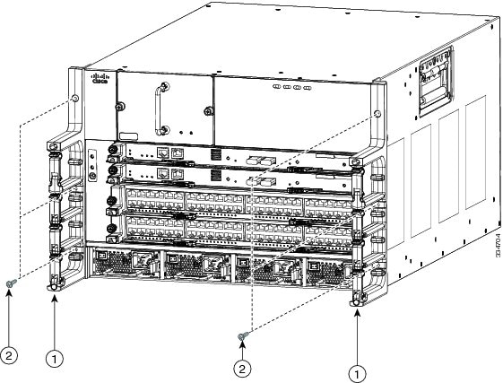
|
|
Guide pins on the cable management frame aligned to two holes in the front-mount bracket. |
|
Three M3 x 10 mm screws used to fasten the frame to the chassis (total of six screws for two frames). |
Step 2![]() Fasten the frame to the chassis with three M3 x 10 mm screws (see Callout 2 in Figure 10-22). Tighten the screws to 5 to 7 in.lbs (0.56 to 0.79 N.m).
Fasten the frame to the chassis with three M3 x 10 mm screws (see Callout 2 in Figure 10-22). Tighten the screws to 5 to 7 in.lbs (0.56 to 0.79 N.m).
Step 3![]() Repeat Steps 1 and 2 to install the other cable management frame to the chassis.
Repeat Steps 1 and 2 to install the other cable management frame to the chassis.
Replacing the Front Doors and Frame Assembly on the Cisco Nexus 7010 Chassis
If the front door and frame assembly are already attached to the chassis when you need to ship the chassis or move the chassis from one rack to another, you should remove the front doors and frame assembly for safer and easier handling of the chassis.
This section describes how to remove and install the front doors and frame assembly, and it includes the following topics:
- Required Tools
- Removing the Front Doors and Frame Assembly
- Installing the Front Doors and Frame Assembly
Required Tools
You need a flat-blade or number 2 Phillips-head screwdriver to loosen or tighten the screws that hold the frame members to the chassis.
Removing the Front Doors and Frame Assembly
Removing the optional front doors and frame assembly involves removing the side frames from the EMI frame, removing the bottom frame assembly, and removing the two front doors.
Note![]() If you are installing a new chassis, you do not need to perform this task because the chassis is not shipped with these assemblies attached to it.
If you are installing a new chassis, you do not need to perform this task because the chassis is not shipped with these assemblies attached to it.
To remove the front doors and frame assemblies, follow these steps:
Step 1![]() Remove the two lower side frames from the EMI air filter frame by first removing the EMI panel from the chassis, and then unscrewing the side frame pieces. When done, replace the EMI frame on the chassis. The following steps explain each of these tasks:
Remove the two lower side frames from the EMI air filter frame by first removing the EMI panel from the chassis, and then unscrewing the side frame pieces. When done, replace the EMI frame on the chassis. The following steps explain each of these tasks:
a.![]() On the EMI panel, which covers the air intake area on the lower front side of the chassis, loosen and completely unscrew each of the four captive screws that hold the panel to the chassis.
On the EMI panel, which covers the air intake area on the lower front side of the chassis, loosen and completely unscrew each of the four captive screws that hold the panel to the chassis.
b.![]() Pull the EMI panel away from the chassis, along with the attached side frame members and optional air filter (if attached) (see Figure 10-18).
Pull the EMI panel away from the chassis, along with the attached side frame members and optional air filter (if attached) (see Figure 10-18).
Figure 10-18 Removing the EMI Panel from the Chassis
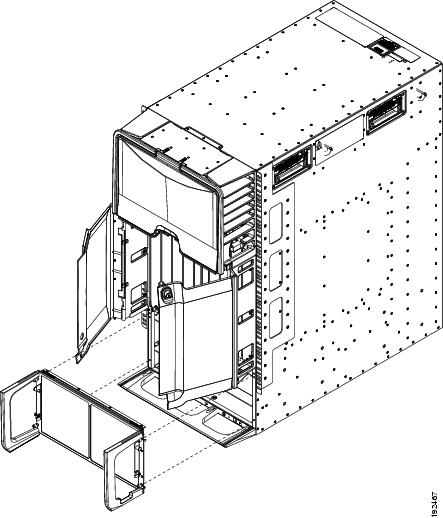
|
|
|
c.![]() From the back of the EMI panel, unscrew each of the four screws that attach the two side frame pieces to the EMI panel, and remove the side frame pieces (see Figure 10-19).
From the back of the EMI panel, unscrew each of the four screws that attach the two side frame pieces to the EMI panel, and remove the side frame pieces (see Figure 10-19).
Figure 10-19 Removing the Side Frame Assemblies from the EMI Panel
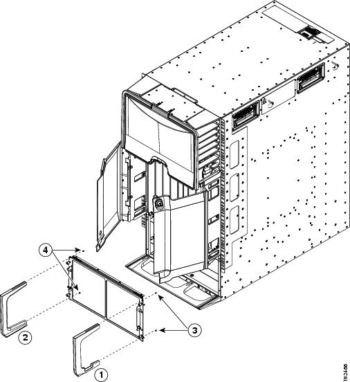
|
|
|
Unscrew two 6-32 x 1/2-inch flat-head screws to remove the right side frame. |
|
|
|
|
Unscrew two 6-32 x 1/2-inch flat-head screws to remove the left side frame. |
d.![]() Realign the EMI panel to the air intake area on the chassis and tighten its four captive screws to 8 in-lb (0.9 N·m).
Realign the EMI panel to the air intake area on the chassis and tighten its four captive screws to 8 in-lb (0.9 N·m).
Step 2![]() Remove the front doors by following these steps:
Remove the front doors by following these steps:
a.![]() Unscrew the three screws that hold one door frame assembly to the chassis until the screws are no longer in the chassis. Remove the door assembly from the chassis. See Figure 10-20.
Unscrew the three screws that hold one door frame assembly to the chassis until the screws are no longer in the chassis. Remove the door assembly from the chassis. See Figure 10-20.
b.![]() Repeat step 4a for the other door assembly.
Repeat step 4a for the other door assembly.
Figure 10-20 Removing the Front Door Assemblies
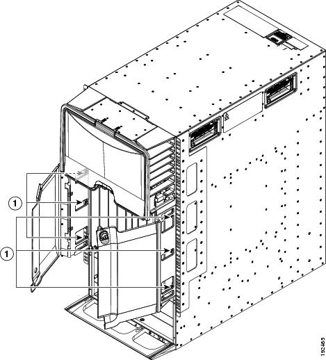
|
|
On each door frame, loosen three captive screws and remove the door frame from the chassis. |
|
Step 3![]() Remove the bottom frame assembly by completely unscrewing the four M4 x 6 mm screws identified in Figure 10-21.
Remove the bottom frame assembly by completely unscrewing the four M4 x 6 mm screws identified in Figure 10-21.
Figure 10-21 Removing the Bottom Frame
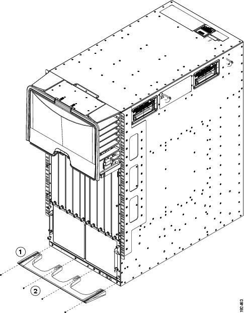
|
|
|
Unscrew four M4 x 6 mm screws that hold the bottom frame to the chassis |
Step 4![]() If you are returning the frame components to Cisco, repack them in their original packing materials.
If you are returning the frame components to Cisco, repack them in their original packing materials.
Installing the Front Doors and Frame Assembly
After you have finished moving the chassis to its rack (or after you have removed the doors and frame for their replacement), you can install the front doors and frame assemblies.
To install the front doors and frame assembly, follow these steps:
Step 1![]() Align the bottom frame assembly so that its four screw holes align to screw holes in the bottom of the chassis, and then screw in four M4 x 6 mm screws to attach the bottom frame to the chassis (see Figure 10-22).
Align the bottom frame assembly so that its four screw holes align to screw holes in the bottom of the chassis, and then screw in four M4 x 6 mm screws to attach the bottom frame to the chassis (see Figure 10-22).
Figure 10-22 Installing the Bottom Frame
|
|
Bottom frame assembly with screw holes aligned to screw holes in chassis. |
|
Step 2![]() For each of the two front doors, match the two alignment pins on the door frame to the alignment holes on the chassis. Position each door frame immediately under the cable management area (see Figure 10-23).
For each of the two front doors, match the two alignment pins on the door frame to the alignment holes on the chassis. Position each door frame immediately under the cable management area (see Figure 10-23).
Figure 10-23 Installing the Front Doors
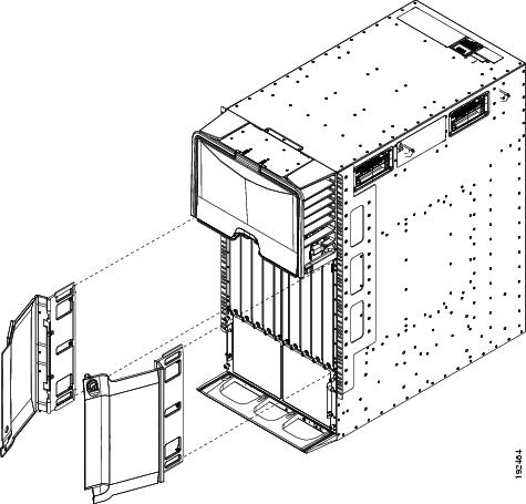
|
|
|
Place each door frame on front edge of chassis and immediately under the cable management area. |
|
|
|
|
Step 3![]() Tighten three captive screws for each door frame (see Figure 10-24).
Tighten three captive screws for each door frame (see Figure 10-24).
Figure 10-24 Attaching the Door Frames to the Chassis
|
|
|
Step 4![]() On the EMI panel, unscrew four captive screws and remove the panel from the chassis (see Figure 10-25).
On the EMI panel, unscrew four captive screws and remove the panel from the chassis (see Figure 10-25).
Figure 10-25 Removing the EMI Panel
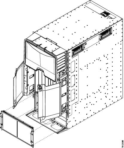
|
|
|
Step 5![]() On the right side of the EMI panel (as seen from the front), align the right frame piece (the one with the notch in one of the two extensions) so that its two screw holes align to two screw holes on one side of the EMI panel and secure the side frame to the panel with two 6-32 x 1/2 inch flat head screws. Tighten the screws to 8 in-lb (0.9 N·m). See Figure 10-26.
On the right side of the EMI panel (as seen from the front), align the right frame piece (the one with the notch in one of the two extensions) so that its two screw holes align to two screw holes on one side of the EMI panel and secure the side frame to the panel with two 6-32 x 1/2 inch flat head screws. Tighten the screws to 8 in-lb (0.9 N·m). See Figure 10-26.
Step 6![]() On the left side of the EMI panel, align the left frame piece (no notch on its extensions) so that its two screw holes align to two screw holes on one side of the EMI panel and secure the side frame to the panel with two 6-32 x 1/2 inch flat head screws. Tighten the screws to 8 in-lb (0.9 N·m). See Figure 10-26.
On the left side of the EMI panel, align the left frame piece (no notch on its extensions) so that its two screw holes align to two screw holes on one side of the EMI panel and secure the side frame to the panel with two 6-32 x 1/2 inch flat head screws. Tighten the screws to 8 in-lb (0.9 N·m). See Figure 10-26.
Figure 10-26 Attaching the Side Frame Assemblies to the EMI Panel
Step 7![]() Realign the EMI panel to the air intake area on the chassis, screw its four captive screws to the chassis, and tighten the captive screws to 8 in-lb (0.9 N·m).
Realign the EMI panel to the air intake area on the chassis, screw its four captive screws to the chassis, and tighten the captive screws to 8 in-lb (0.9 N·m).
Replacing the Cable Management Frame on the Cisco Nexus 7018 Chassis
This section describes how to remove cable management frame components and install the components for a replacement frame. The cable management frame includes two lower cable management assemblies, two upper cable management assemblies, and a top cover.
This section includes the following topics:
Required Tools
You need a flat-blade or number 2 Phillips-head screwdriver to loosen or tighten the screws that hold the cable management assemblies to the chassis.
Removing the Cable Management Frame
When you remove the cable management frame from the Cisco Nexus 7018 chassis, you must remove a top cover and four cable management assemblies.
Note![]() Before you can remove the cable management frame from the Cisco Nexus 7018 chassis, you must remove the front door and its bracket if they are installed on the cable management frame. For information on removing the front door and its bracket, see the “Replacing the Front Door and Air Intake Assemblies on the Cisco Nexus 7018 Chassis” section.
Before you can remove the cable management frame from the Cisco Nexus 7018 chassis, you must remove the front door and its bracket if they are installed on the cable management frame. For information on removing the front door and its bracket, see the “Replacing the Front Door and Air Intake Assemblies on the Cisco Nexus 7018 Chassis” section.
To remove the cable management frame assemblies, follow these steps:
Step 1![]() Loosen and remove the eight M4x8 pan-head screws that fasten the top cover to the upper cable management assemblies and chassis (see Figure 10-27).
Loosen and remove the eight M4x8 pan-head screws that fasten the top cover to the upper cable management assemblies and chassis (see Figure 10-27).
Figure 10-27 Detaching the Top Cover from the Upper-Cable-Management Assemblies and Chassis
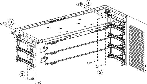
|
|
|
Four M4x8 pan-head screws fastened to the two upper cable management assemblies |
Step 2![]() Remove the top cover from the chassis and the two upper cable management assemblies.
Remove the top cover from the chassis and the two upper cable management assemblies.
Step 3![]() For the upper cable management assembly on the left, loosen and remove five M4x10 screws, and then lift off the assembly as shown in Figure 10-28.
For the upper cable management assembly on the left, loosen and remove five M4x10 screws, and then lift off the assembly as shown in Figure 10-28.
Step 4![]() Repeat Step 3 for the upper cable management assembly on the right side.
Repeat Step 3 for the upper cable management assembly on the right side.
Figure 10-28 Removing an Upper-Cable-Management Assembly

|
|
|
||
|
|
|
Lift the upper cable management assembly off the rack-mount bracket hooks. |
Step 5![]() For the lower cable management assembly on the left, loosen and remove four M4x10 screws, and then lift off the assembly as shown in Figure 10-29.
For the lower cable management assembly on the left, loosen and remove four M4x10 screws, and then lift off the assembly as shown in Figure 10-29.
Figure 10-29 Removing a Lower Cable Management Assembly

|
|
|
||
|
|
|
Lift the lower cable management assembly off the rack-mount bracket hooks. |
Step 6![]() Repeat Step 5 for the lower cable management assembly on the right side.
Repeat Step 5 for the lower cable management assembly on the right side.
Step 7![]() Pack the two lower cable management assemblies, two upper cable management assemblies, the top cover, and their screws in their original packing materials.
Pack the two lower cable management assemblies, two upper cable management assemblies, the top cover, and their screws in their original packing materials.
Installing a Cable Management Frame
When you install a cable management frame, you attach four cable management assemblies to the chassis and then attach a top cover to the top two cable management assemblies and the chassis.
To install the cable management frame on the Cisco Nexus 7018 switch chassis, follow these steps:
Step 1![]() Open the Cable Management kit (69-1961-01) and verify that you have the following parts:
Open the Cable Management kit (69-1961-01) and verify that you have the following parts:
- 2 lower cable management assemblies (800-31343-01)
- 2 upper cable management assemblies (800-31342-01)
- 1 top cover (800-31269-01)
- 8 M4x8 pan-head screws (48-0398-01)
- 18 M4x10 flat-head screws (48-2518-01)
If the kit is not complete, contact TAC and arrange for a complete kit.
Step 2![]() Attach a lower cable management assembly onto the two hooks that protrude from the lower half of the left rack-mount bracket that is attached to the Cisco Nexus 7018 switch chassis, and loosely fasten the assembly to the chassis with four flat-head M4x10 screws as shown in Figure 10-30.
Attach a lower cable management assembly onto the two hooks that protrude from the lower half of the left rack-mount bracket that is attached to the Cisco Nexus 7018 switch chassis, and loosely fasten the assembly to the chassis with four flat-head M4x10 screws as shown in Figure 10-30.
Figure 10-30 Attaching a Lower Cable Management Assembly to a Rack-Mount Bracket
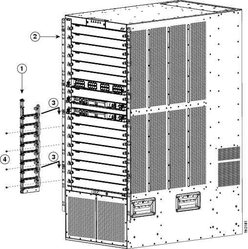
Step 3![]() Repeat Step 1 to attach a lower cable management assembly to the right side of the chassis.
Repeat Step 1 to attach a lower cable management assembly to the right side of the chassis.
Step 4![]() Attach an upper cable management assembly onto the two hooks that protrude from the upper half of the left rack-mount bracket that is attached to the Cisco Nexus 7018 switch chassis, and loosely fasten the assembly to the chassis with four flat-head M4x10 screws as shown in Figure 10-31.
Attach an upper cable management assembly onto the two hooks that protrude from the upper half of the left rack-mount bracket that is attached to the Cisco Nexus 7018 switch chassis, and loosely fasten the assembly to the chassis with four flat-head M4x10 screws as shown in Figure 10-31.
Figure 10-31 Attaching an Upper Cable Management Assembly to a Rack-Mount Bracket
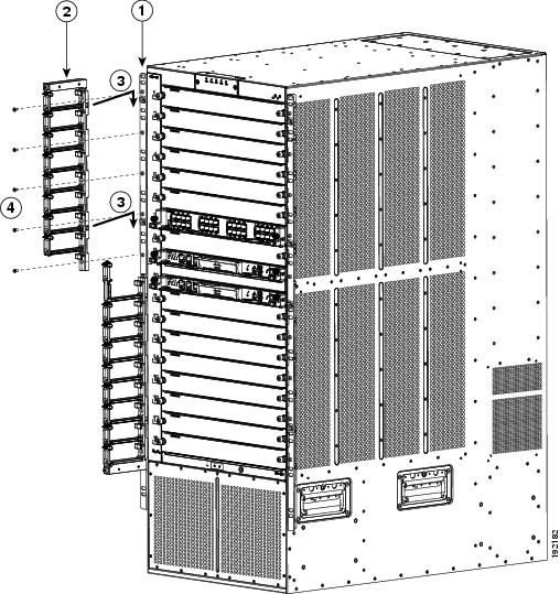
Step 5![]() Repeat Step 3 to attach an upper cable management assembly to the upper right side of the chassis. When completed, the chassis will appear as shown in Figure 10-32.
Repeat Step 3 to attach an upper cable management assembly to the upper right side of the chassis. When completed, the chassis will appear as shown in Figure 10-32.
Figure 10-32 Cable Management Assemblies Attached to the Rack-Mount Brackets
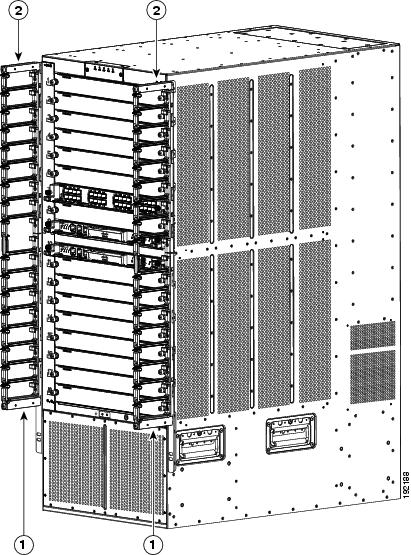
|
|
|
Step 6![]() Place the top cover on top of the two upper cable management assemblies that are already installed. Make sure that the side of the top cover that is closest to the chassis has two alignment pins that align with the alignment holes in the chassis as shown in Figure 10-33. Push the top cover toward the chassis so that its alignment pins enter the alignment holes and the top cover rests against the chassis.
Place the top cover on top of the two upper cable management assemblies that are already installed. Make sure that the side of the top cover that is closest to the chassis has two alignment pins that align with the alignment holes in the chassis as shown in Figure 10-33. Push the top cover toward the chassis so that its alignment pins enter the alignment holes and the top cover rests against the chassis.
Figure 10-33 Positioning the Top Cover with the Upper Cable Management Assemblies and the Switch Chassis
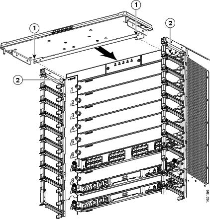
|
|
|
Step 7![]() Use four M4x8 pan-head screws to loosely fasten the top cover to the chassis (see Callout 1 in Figure 10-34).
Use four M4x8 pan-head screws to loosely fasten the top cover to the chassis (see Callout 1 in Figure 10-34).
Figure 10-34 Fastening the Top Cover to the Chassis and Cable Management Assemblies
|
|
Four M4x8 pan-head screws that fasten the top cover to the chassis. |
|
Four M4x8 pan-head screws that fasten the top cover to the left and right cable management assemblies. |
Step 8![]() Use four M4x8 pan-head screws to loosely fasten the top cover to each of the two upper cable management assemblies (see Callout 2 in Figure 10-34).
Use four M4x8 pan-head screws to loosely fasten the top cover to each of the two upper cable management assemblies (see Callout 2 in Figure 10-34).
Step 9![]() Tighten each of the four screws that fasten the top cover to the chassis to 11 to 15 in-lb (1.2 to 1.7 N·m).
Tighten each of the four screws that fasten the top cover to the chassis to 11 to 15 in-lb (1.2 to 1.7 N·m).
Step 10![]() Tighten each of the four screws that fasten the top cover to the upper cable management assemblies to 11 to 15 in-lb (1.2 to 1.7 N·m).
Tighten each of the four screws that fasten the top cover to the upper cable management assemblies to 11 to 15 in-lb (1.2 to 1.7 N·m).
Step 11![]() Tighten each of the 18 screws that fasten the upper and lower cable management assemblies to the rack-mount brackets to 11 to 15 in-lb (1.2 to 1.7 N·m).
Tighten each of the 18 screws that fasten the upper and lower cable management assemblies to the rack-mount brackets to 11 to 15 in-lb (1.2 to 1.7 N·m).
Replacing the Front Door and Air Intake Assemblies on the Cisco Nexus 7018 Chassis
If you are going to move the Cisco Nexus 7018 chassis or if you need to replace the door and air intake assembly, you must first remove the installed door and air intake assemblies.
Note![]() For the double-hinged door to easily open or close in either direction, make sure that the chassis is level. If necessary, remove the chassis from the rack and adjust the bottom-support rails so that the chassis is level. Also, make sure that the cable management assemblies are aligned to the vertical sides of the chassis and that the cable management top cover is level when you install those components.
For the double-hinged door to easily open or close in either direction, make sure that the chassis is level. If necessary, remove the chassis from the rack and adjust the bottom-support rails so that the chassis is level. Also, make sure that the cable management assemblies are aligned to the vertical sides of the chassis and that the cable management top cover is level when you install those components.
This section includes the following topics:
- Removing the Front Door and Air Intake Assemblies
- Cleaning or Replacing the Air Filter for the Cisco Nexus 7010 Chassis
Removing the Front Door and Air Intake Assemblies
When you remove the front door and air intake assemblies, you remove the door, air intake assembly, and the hardware used to hold those components to the chassis.
To remove the front door and air intake assemblies on the Cisco Nexus 7018 chassis, follow these steps:
Step 1![]() Remove the front door by following these steps:
Remove the front door by following these steps:
a.![]() Open the door by pulling one of its latch handles out until it clicks (the handle clicks when you pull it out about 30 degrees) and rotating the door away from the chassis (see Callouts 1 and 2 in Figure 10-35).
Open the door by pulling one of its latch handles out until it clicks (the handle clicks when you pull it out about 30 degrees) and rotating the door away from the chassis (see Callouts 1 and 2 in Figure 10-35).
Figure 10-35 Opening the Front Door
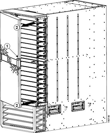
|
|
|
b.![]() Press the locking button on the back side of the door (behind the opened latch handle) so that the latch handle flattens to the front side of the door (see Figure 10-36).
Press the locking button on the back side of the door (behind the opened latch handle) so that the latch handle flattens to the front side of the door (see Figure 10-36).
Figure 10-36 Flattening the Latch Handle to the Door
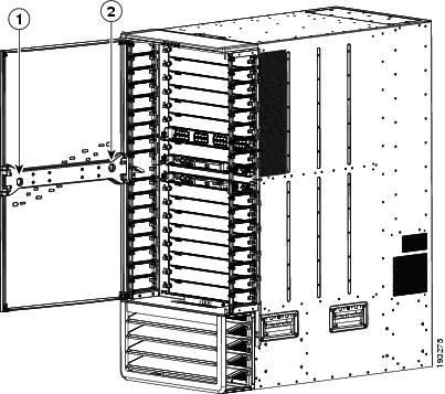
|
|
If you opened the right side of the door (as shown in this figure), press the locking button on the right side. |
|
If you opened the left side of the door, press the locking button on the left side. |
c.![]() Hold the opened side of the door with one hand and use your other hand to open the latch handle on the hinged side of the door (see Callout 1 in Figure 10-37) until the handle clicks.
Hold the opened side of the door with one hand and use your other hand to open the latch handle on the hinged side of the door (see Callout 1 in Figure 10-37) until the handle clicks.
Figure 10-37 Removing the Front Door from the Chassis
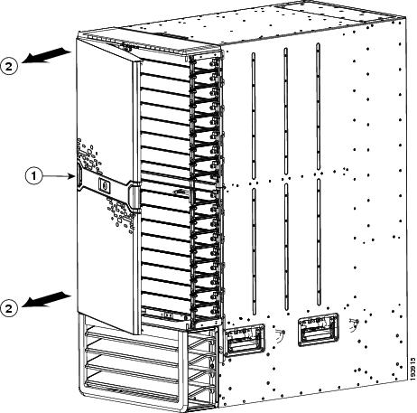
|
|
|
d.![]() Holding the door with both hands, pull the door away from the chassis (see Callout 2 in Figure 10-37).
Holding the door with both hands, pull the door away from the chassis (see Callout 2 in Figure 10-37).
e.![]() Press the locking button on the inside surface of the door behind the opened latch to flatten the latch handle to the front side of the door (see Figure 10-36).
Press the locking button on the inside surface of the door behind the opened latch to flatten the latch handle to the front side of the door (see Figure 10-36).
f.![]() Open the box for the front door. You can find this box in the box that contains the front door and air frame kit. Align the four side cushions to the sides of the center panel of the box (see Callouts 1 and 2 in Figure 10-38).
Open the box for the front door. You can find this box in the box that contains the front door and air frame kit. Align the four side cushions to the sides of the center panel of the box (see Callouts 1 and 2 in Figure 10-38).
Figure 10-38 Packing the Front Door
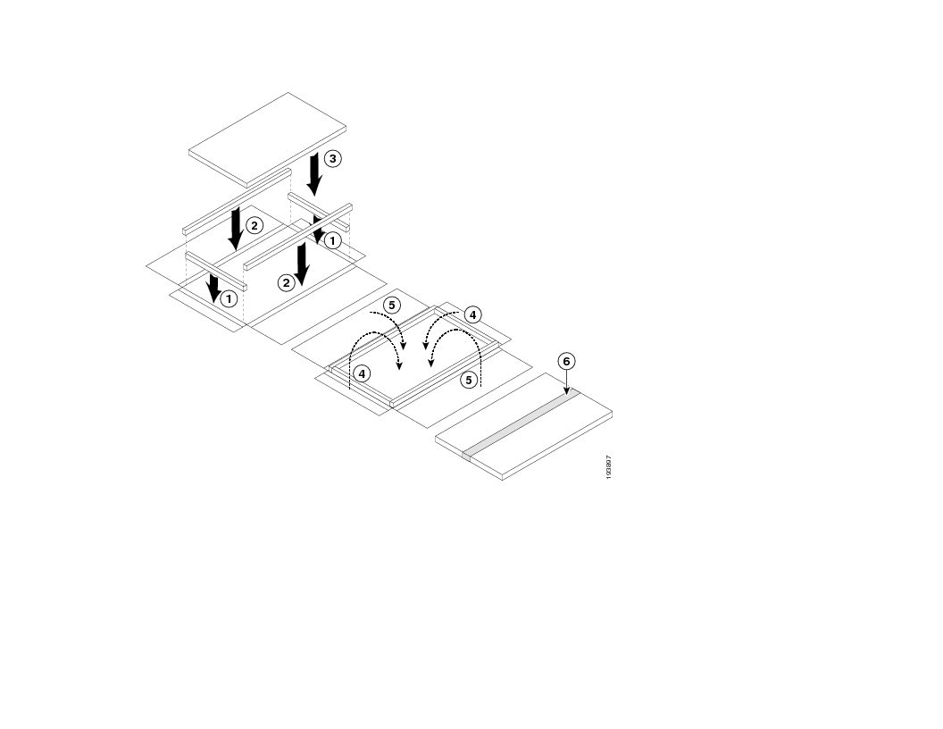
g.![]() Fold the short side flaps of the box over the top and bottom ends of the door.
Fold the short side flaps of the box over the top and bottom ends of the door.
h.![]() Fold the wider side flaps of the box over the door and tape them together.
Fold the wider side flaps of the box over the door and tape them together.
i.![]() Loosen and remove the eight screws holding the bottom hinge bracket for the door. Four of the screws are attached to the left and right side of the cable management frame (two screws on each side) and four of the screws are attached to the chassis (see Figure 10-39). Place the screws in the small parts bag.
Loosen and remove the eight screws holding the bottom hinge bracket for the door. Four of the screws are attached to the left and right side of the cable management frame (two screws on each side) and four of the screws are attached to the chassis (see Figure 10-39). Place the screws in the small parts bag.
Figure 10-39 Removing the Bottom Hinge Bracket
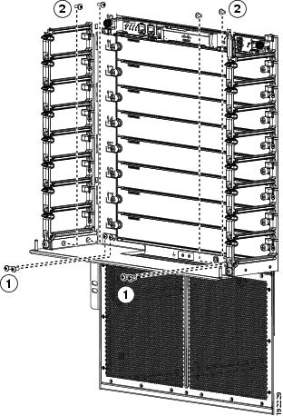
|
|
Remove four M4 x 8 screws from the cable management assemblies (two screws on each side) |
|
j.![]() Remove the bracket from the chassis and place it in the opened box for that component.
Remove the bracket from the chassis and place it in the opened box for that component.
k.![]() Fold the box flaps over the bracket and tape them in place.
Fold the box flaps over the bracket and tape them in place.
l.![]() Loosen and remove the two M3 x 10 screws that hold the right door stopper to the right cable management frame. Place the two screws and the door stopper in the small parts bag.
Loosen and remove the two M3 x 10 screws that hold the right door stopper to the right cable management frame. Place the two screws and the door stopper in the small parts bag.
m.![]() Loosen and remove the two M3 x 10 screws that hold the left door stopper to the left cable management frame. Place the two screws and the door stopper in the small parts bag.
Loosen and remove the two M3 x 10 screws that hold the left door stopper to the left cable management frame. Place the two screws and the door stopper in the small parts bag.
n.![]() Fold the box flaps over the top and tape them in place.
Fold the box flaps over the top and tape them in place.
o.![]() While holding the air intake frame in place, loosen the two captive screws on the air intake frame (there is one captive screw on each side of that frame) so that they are no longer in contact with the chassis (see Callout 1 in Figure 10-40).
While holding the air intake frame in place, loosen the two captive screws on the air intake frame (there is one captive screw on each side of that frame) so that they are no longer in contact with the chassis (see Callout 1 in Figure 10-40).
Figure 10-40 Removing the Air Intake Assembly
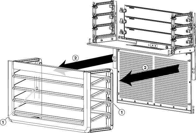
|
|
Loosen two captive screws until they are clear of the chassis. |
|
p.![]() Pull the air intake assembly off the chassis.
Pull the air intake assembly off the chassis.
q.![]() Loosen and remove the four ball-point studs shown in Figure 10-41.
Loosen and remove the four ball-point studs shown in Figure 10-41.
r.![]() Repack the air intake frame and ball-point studs in their original packing materials.
Repack the air intake frame and ball-point studs in their original packing materials.
Figure 10-41 Removing the Four Ball-Headed Studs
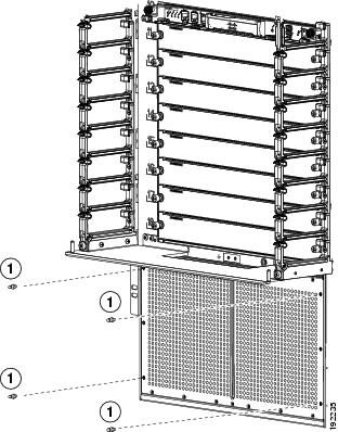
|
|
|
s.![]() Repack the air intake frame and ball-point studs in their original packing box, then fold over the box flaps and tape them shut.
Repack the air intake frame and ball-point studs in their original packing box, then fold over the box flaps and tape them shut.
t.![]() Open the box for the front door and air intake frame kit and insert the components as shown in Figure 10-42.
Open the box for the front door and air intake frame kit and insert the components as shown in Figure 10-42.
u.![]() Close the box flaps and tape them shut.
Close the box flaps and tape them shut.
Figure 10-42 Packing the Front Door and Air Intake Frame Kit
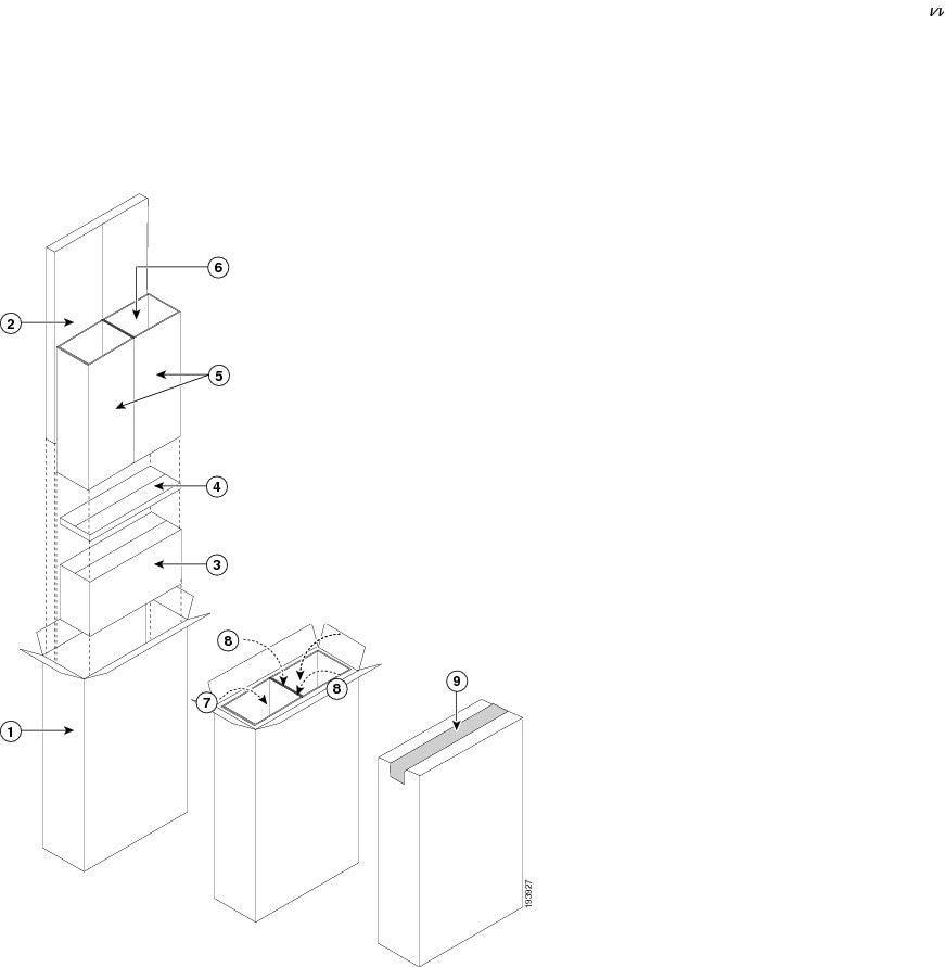
|
|
|
||
|
|
|
||
|
|
|
||
|
|
|
||
|
|
|
To replace the front door and air intake assemblies, see the “Installing a Front Door and Air Intake Assemblies” section.
Installing a Front Door and Air Intake Assemblies
When you install a front door and air intake assembly components, you install hardware to hold the door and air intake assemblies, attach the door, and then attach the air intake assembly.
To install the front door and air intake assembly components, follow these steps:
Step 1![]() Open the Front Door and Air Intake kit (69-1962-01) and verify that it includes the following components:
Open the Front Door and Air Intake kit (69-1962-01) and verify that it includes the following components:
- 1 front door (800-31268-01)
- 1 air intake frame (800-31270-01)
- 1 bottom hinge bracket (700-28491-02)
- 1 left door stopper (has an L on its base) (700-27454-01)
- 1 right door stopper (has an R on its base) (700-27592-01)
- 8 M4x8 pan head screws (48-0398-01)
- 4 M3x14 pan head screws (48-1699-01)
- 4 ball-point studs (51-5171-01)
Step 2![]() Position the left door stopper (has an L on its base) on the middle of the left side of the cable management frame and fasten it with two M3x14 pan-head screws as shown in Figure 10-43. Tighten these two screws to 8.4 to 11 in-lb (0.9 to 1.2 N·m).
Position the left door stopper (has an L on its base) on the middle of the left side of the cable management frame and fasten it with two M3x14 pan-head screws as shown in Figure 10-43. Tighten these two screws to 8.4 to 11 in-lb (0.9 to 1.2 N·m).
Figure 10-43 Attaching the Left Door Stopper
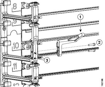
|
|
Left door stopper identified with an L on the bottom of the base. |
|
|
|
|
Two M3x14 screws that fasten the stopper to the left side of the cable management assembly. |
|
Step 3![]() Position the right door stopper (has an R on its base) on the middle of the right side of the cable management frame and fasten it with two M3x14 pan-head screws as shown in Figure 10-44. Tighten these two screws to 8.4 to 11 in-lb (0.9 to 1.2 N·m).
Position the right door stopper (has an R on its base) on the middle of the right side of the cable management frame and fasten it with two M3x14 pan-head screws as shown in Figure 10-44. Tighten these two screws to 8.4 to 11 in-lb (0.9 to 1.2 N·m).
Figure 10-44 Attaching the Right Door Stopper
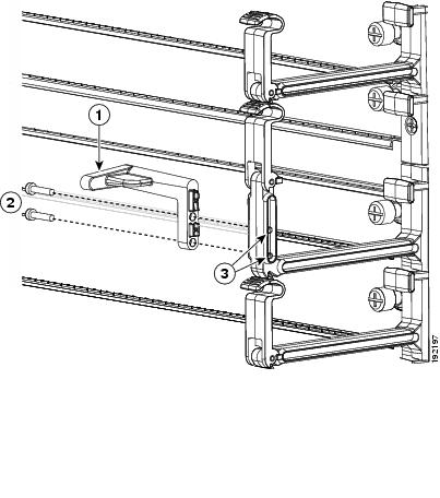
Step 4![]() Position the bottom hinge bracket at the bottom of both sides of the cable management frame. Make sure that the side of the bracket that is closest to the chassis has two alignment pins that align with the alignment holes in the chassis as shown in Figure 10-45. Push the bracket toward the chassis so that its alignment pins enter the alignment holes and the bracket rests against the chassis.
Position the bottom hinge bracket at the bottom of both sides of the cable management frame. Make sure that the side of the bracket that is closest to the chassis has two alignment pins that align with the alignment holes in the chassis as shown in Figure 10-45. Push the bracket toward the chassis so that its alignment pins enter the alignment holes and the bracket rests against the chassis.
Figure 10-45 Positioning the Hinge Bracket to the Cable Management Frame and Chassis
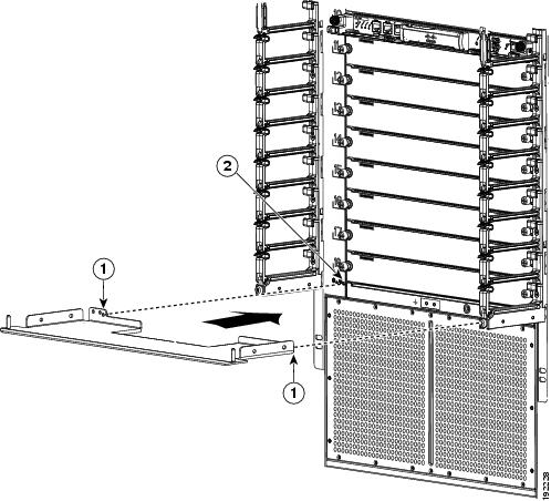
|
|
|
Step 5![]() Attach the bottom hinge bracket to the chassis with eight loosely fastened M4x8 screws (see Callout 1 in Figure 10-46).
Attach the bottom hinge bracket to the chassis with eight loosely fastened M4x8 screws (see Callout 1 in Figure 10-46).
Step 6![]() Attach the bottom hinge bracket to the bottom of both sides of the cable management frame (see Callout 2 in Figure 10-46).
Attach the bottom hinge bracket to the bottom of both sides of the cable management frame (see Callout 2 in Figure 10-46).
Figure 10-46 Attaching the Hinge Bracket to the Cable Management Frame and Chassis
Step 7![]() Tighten the four M4x8 screws that fasten the bottom hinge bracket to the chassis to 11 to 15 in-lb (1.2 to 1.7 N·m).
Tighten the four M4x8 screws that fasten the bottom hinge bracket to the chassis to 11 to 15 in-lb (1.2 to 1.7 N·m).
Step 8![]() Tighten the four M4x8 screws that fasten the bottom hinge bracket to the cable management frame to 11 to 15 in-lb (1.2 to 1.7 N·m).
Tighten the four M4x8 screws that fasten the bottom hinge bracket to the cable management frame to 11 to 15 in-lb (1.2 to 1.7 N·m).
Step 9![]() Fasten the four ball-point studs to the bottom portion of the chassis, one stud by each corner of the air intake area as shown in Figure 10-47.
Fasten the four ball-point studs to the bottom portion of the chassis, one stud by each corner of the air intake area as shown in Figure 10-47.
Figure 10-47 Fastening Ball-Point Studs to the Air Intake Area
|
|
|
Step 10![]() Align the air intake frame to the four ball-point studs and press the frame onto the chassis, as shown in Figure 10-48. The two captive screws on the air-intake frame should align with their screw holes in the chassis.
Align the air intake frame to the four ball-point studs and press the frame onto the chassis, as shown in Figure 10-48. The two captive screws on the air-intake frame should align with their screw holes in the chassis.
Figure 10-48 Positioning the Air Intake Frame on the Chassis
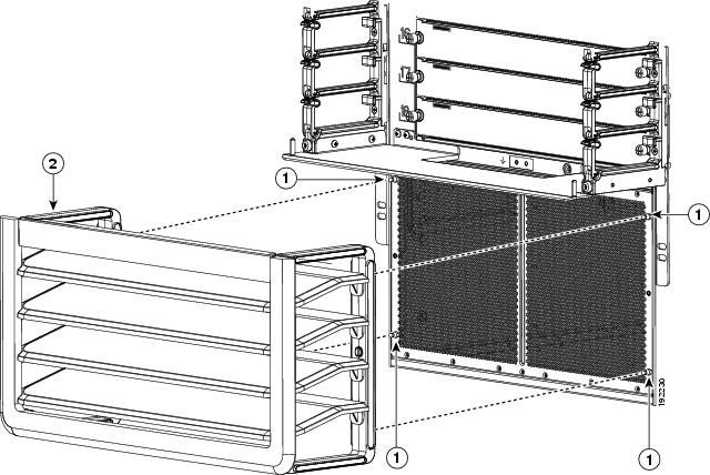
|
|
|
Air-intake frame with holes to be aligned with the ball-point studs |
Step 11![]() Fasten the captive screws on the air intake frame to the chassis and tighten to 11 to 15 in-lb (95 to 130 N·m).
Fasten the captive screws on the air intake frame to the chassis and tighten to 11 to 15 in-lb (95 to 130 N·m).
Step 12![]() On the chassis door, pull the door handle open on one of the two sides of the door until the handle clicks (the handle clicks when you pull it out about 30 degrees).
On the chassis door, pull the door handle open on one of the two sides of the door until the handle clicks (the handle clicks when you pull it out about 30 degrees).
Step 13![]() Move the side of the door with the opened handle onto the two hinge pins as shown in Figure 10-49. Make sure that the hinge pins on the top cover and bottom hinge bracket fit through the slots on the top and bottom of that side of the door. Position the door so the hinge pins are located at the ends of the slots.
Move the side of the door with the opened handle onto the two hinge pins as shown in Figure 10-49. Make sure that the hinge pins on the top cover and bottom hinge bracket fit through the slots on the top and bottom of that side of the door. Position the door so the hinge pins are located at the ends of the slots.
Note![]() The double-hinged door can be installed and opened on either side. The figures in this procedure show how to install the door on the left side first, but you can use the instructions to install it on either side first.
The double-hinged door can be installed and opened on either side. The figures in this procedure show how to install the door on the left side first, but you can use the instructions to install it on either side first.
Figure 10-49 Attaching One Side of the Door to the Chassis
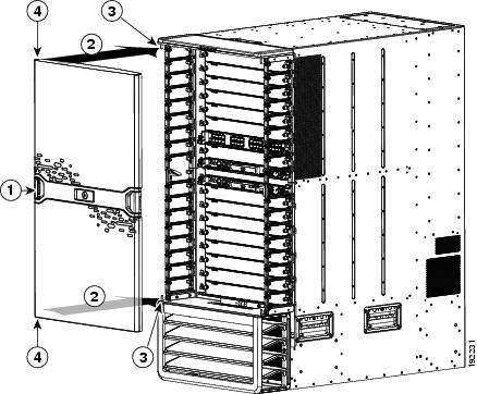
|
|
|
||
|
|
Move one side of the door to the hinge pins on the same side of the chassis. |
|
Step 14![]() Use one hand to hold the door on the hinge pins and use your other hand to press the locking button on the interior side of the door (see Figure 10-50). This action locks the latches on one side of the door to the hinge pins so that you no longer need to hold the door.
Use one hand to hold the door on the hinge pins and use your other hand to press the locking button on the interior side of the door (see Figure 10-50). This action locks the latches on one side of the door to the hinge pins so that you no longer need to hold the door.
Figure 10-50 Locking the Door onto the Chassis
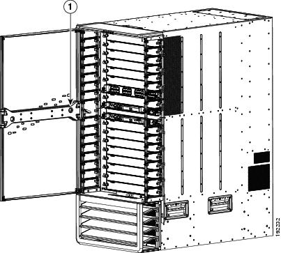
|
|
Press the locking button to lock the door onto the hinge pins. |
|
Note![]() Be sure that the door is firmly latched to the two hinge pins. If both of the hinge pins are not secured behind the door latch, hold the door securely with one hand while opening the door handle for the unsecured side until the handle clicks, press that side of the door so that both of the pins are positioned all the way inside the door slots, press the door latch button on the interior side of the door, and then make sure that the door is firmly secured to both hinge pins.
Be sure that the door is firmly latched to the two hinge pins. If both of the hinge pins are not secured behind the door latch, hold the door securely with one hand while opening the door handle for the unsecured side until the handle clicks, press that side of the door so that both of the pins are positioned all the way inside the door slots, press the door latch button on the interior side of the door, and then make sure that the door is firmly secured to both hinge pins.
Step 15![]() Open the door handle on the open side of the door until it clicks. This action opens the latches on the open side of the door. See Figure 10-51.
Open the door handle on the open side of the door until it clicks. This action opens the latches on the open side of the door. See Figure 10-51.
Figure 10-51 Attaching the Right Side of the Door
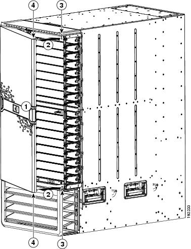
|
|
|
||
|
|
|
Step 16![]() Swing the door closed so that the remaining two pins on the bottom hinge bracket and top cover fit inside the slots on the top and bottom of the door. When you close the door, the door stopper automatically presses the lock button on the inside of the door so that the door is locked on the hinge pins. If the door stopper does not close the latches, press the door closed at the handle until you hear the latches click. Make sure that the door is fully secured to the frames on both sides.
Swing the door closed so that the remaining two pins on the bottom hinge bracket and top cover fit inside the slots on the top and bottom of the door. When you close the door, the door stopper automatically presses the lock button on the inside of the door so that the door is locked on the hinge pins. If the door stopper does not close the latches, press the door closed at the handle until you hear the latches click. Make sure that the door is fully secured to the frames on both sides.
Note![]() If a hinge pin is not secured behind a door latch, open the door handle for that side of the door until it clicks, open that side of the door, and then press the door closed so that the pins are positioned all the way inside the door slots. When you close the door, the door stopper automatically closes the door latches. If you do not hear the latches click, press the door at the handle to fully close it and to activate the latches. Test the door to make sure that it is fully secured to the four hinge pins.
If a hinge pin is not secured behind a door latch, open the door handle for that side of the door until it clicks, open that side of the door, and then press the door closed so that the pins are positioned all the way inside the door slots. When you close the door, the door stopper automatically closes the door latches. If you do not hear the latches click, press the door at the handle to fully close it and to activate the latches. Test the door to make sure that it is fully secured to the four hinge pins.
Tip![]() Whenever you need to open the door, pull one of the latch handles open until it clicks and then swing that side of the door open.
Whenever you need to open the door, pull one of the latch handles open until it clicks and then swing that side of the door open.
Note![]() If the double-hinged door and its holders are not level, it is possible that you will have some difficulty opening or closing the door on one or both sides without the door being defective. Either push in the bottom portion of the door or slightly lift up the door on that side just before closing. If the problem persists, open the door from the other side, which should be free of this problem, or adjust the cable management system and hinge bracket so that they are level.
If the double-hinged door and its holders are not level, it is possible that you will have some difficulty opening or closing the door on one or both sides without the door being defective. Either push in the bottom portion of the door or slightly lift up the door on that side just before closing. If the problem persists, open the door from the other side, which should be free of this problem, or adjust the cable management system and hinge bracket so that they are level.
Replacing the Air Filter on the Cisco Nexus 7004 Chassis
You can replace the optional air filter while the Cisco Nexus 7004 system is operational.
Note![]() We recommend that you check the air filter once a month. If it is covered with a significant amount of dust, replace the air filter.
We recommend that you check the air filter once a month. If it is covered with a significant amount of dust, replace the air filter.
To replace the air filter, follow these steps:
Step 1![]() On the right side of the chassis, remove eight screws that hold the airfilter to the chassis.
On the right side of the chassis, remove eight screws that hold the airfilter to the chassis.
Step 3![]() Place the new air filter over the air intake area on the right side of the chassis and align the eight screw holes in the filter to screw holes in the chassis.
Place the new air filter over the air intake area on the right side of the chassis and align the eight screw holes in the filter to screw holes in the chassis.
Step 4![]() Fasten the air filter to the chassis using eight M3 x 5 mm screws that came with the air filter.. Tighten the screws to 5 to 7 in-lb (0.56 to 0.79 N.m).
Fasten the air filter to the chassis using eight M3 x 5 mm screws that came with the air filter.. Tighten the screws to 5 to 7 in-lb (0.56 to 0.79 N.m).
Cleaning or Replacing the Air Filter for the Cisco Nexus 7010 Chassis
You can clean or replace the optional air filter while the Cisco Nexus 7010 system is operational.
Note![]() We recommend that you check the air filter once a month. If it is covered with an oily substance, you should replace it. If it is covered with dust, you can clean it and continue to use it.
We recommend that you check the air filter once a month. If it is covered with an oily substance, you should replace it. If it is covered with dust, you can clean it and continue to use it.
To clean or replace the air filter, follow these steps:
Step 1![]() On the left and right side of the existing air filter, loosen the two captive screws so they are no longer attached to the chassis. The air filter can be found covering the air intake area at the bottom of the front side of the chassis (see Figure 1-5).
On the left and right side of the existing air filter, loosen the two captive screws so they are no longer attached to the chassis. The air filter can be found covering the air intake area at the bottom of the front side of the chassis (see Figure 1-5).
Step 2![]() With one hand holding the air filter in place, use the other hand to pull out the spring pin on one side of the air filter. Pull that side of the air filter away from the chassis and release the spring pin when it is clear of the bracket on the EMI frame.
With one hand holding the air filter in place, use the other hand to pull out the spring pin on one side of the air filter. Pull that side of the air filter away from the chassis and release the spring pin when it is clear of the bracket on the EMI frame.
Step 3![]() Switch the hands holding the air filter and use the other hand to pull out the spring pin on the other side of the air filter. Pull the air filter away from the chassis and release the spring pin.
Switch the hands holding the air filter and use the other hand to pull out the spring pin on the other side of the air filter. Pull the air filter away from the chassis and release the spring pin.
Step 4![]() If the filter is covered with an oily substance, we recommend that you replace it. If the filter is dusty, you can take it outside the data center and clean it in one or more of the following ways:
If the filter is covered with an oily substance, we recommend that you replace it. If the filter is dusty, you can take it outside the data center and clean it in one or more of the following ways:
- Use a vacuum cleaner over both sides of the filter.
- Blow compressed air through the exhaust side of the filter.
- Rinse the filter with cold water.
- Immerse the filter in warm, soapy water, and then rinse it.
Note![]() If the filter gets wet while you clean it, make sure that it dries before you reinstall it.
If the filter gets wet while you clean it, make sure that it dries before you reinstall it.
Step 5![]() Align the cleaned or replacement air filter to the EMI frame covering the air intake area.
Align the cleaned or replacement air filter to the EMI frame covering the air intake area.
Step 6![]() Use one hand on the air filter to hold it in place while you use the other hand to pull out the spring pin on one side of the air filter. Adjust the air filter so that the spring pin will be released into its hole in the EMI frame bracket.
Use one hand on the air filter to hold it in place while you use the other hand to pull out the spring pin on one side of the air filter. Adjust the air filter so that the spring pin will be released into its hole in the EMI frame bracket.
Step 7![]() Switch the hands holding the air filter and use the other hand to pull out the other spring pin on the other side of the air filter. With the spring pin pulled out, position the air filter so that the pin will be released into its hole on the EMI frame bracket. Release the spring pin and make sure that it holds the air filter on to the EMI frame.
Switch the hands holding the air filter and use the other hand to pull out the other spring pin on the other side of the air filter. With the spring pin pulled out, position the air filter so that the pin will be released into its hole on the EMI frame bracket. Release the spring pin and make sure that it holds the air filter on to the EMI frame.
Step 8![]() Screw in and tighten both captive screws, one on each side of the air filter.
Screw in and tighten both captive screws, one on each side of the air filter.
 Feedback