- Preface
- Overview
- Installing a Cisco Nexus 7004 Switch
- Installing a Cisco Nexus 7009 Chassis
- Installing a Cisco Nexus 7010 Chassis
- Installing a Cisco Nexus 7018 Chassis
- Installing Power Supply Units
- Connecting the Cisco Nexus 7000 Switch to the Network
- Managing system hardware
- Troubleshooting
- Replacement Procedures
- Technical Specifications
- Transceiver and Module Connectors
- Cisco Nexus 7000 Series Accessory Kit Contents
- Chassis and Module LEDs
- Repacking the Nexus 7000 Series Switch for Shipment
- Site Preparation and Maintenance Records
Overview
This chapter provides an overview of the Cisco Nexus 7000 Series switch and includes the following sections:
Cisco Nexus 7000 Series
The Cisco Nexus 7000 Series switches are multiprotocol-capable, high-density, and high-performance switches that incorporate Ethernet/IP, virtualization, Layer 4 to Layer 7 services, and low-latency interconnect (LLI) technologies. The Cisco Nexus 7000 Series models are described in the following topics:
Cisco Nexus 7004 Switch
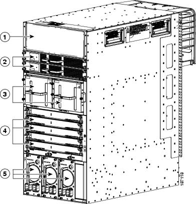
The Cisco Nexus 7004 chassis has four slots that allow for one or two supervisor modules and up to two I/O modules. Additionally, the chassis holds a fan tray, up to four power supplies, and cable management frames. Optionally, you can include a door and air filter. Figure 1-1 identifies these features as seen from the front of the chassis.
Figure 1-1 Standard Hardware Features on the Front and Sides of the Cisco Nexus 7004 Chassis
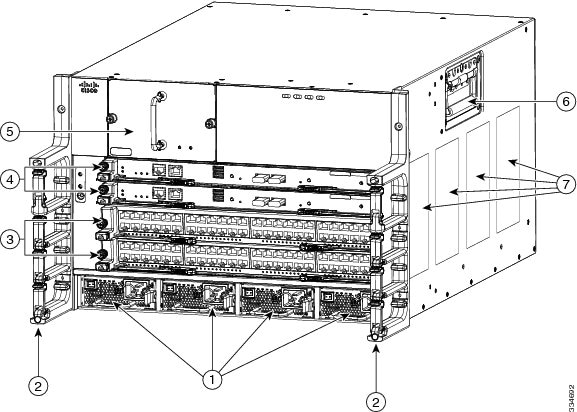

Note![]() Figure 1-1 shows the Cisco Nexus 7004 chassis as it appears when it is fully configured before including cables for management and network connections. The systems that are not fully configured with the maximum number of supervisor modules, I/O modules, or power supply units have blank panels installed in place of the missing components to maintain the designed airflow for system cooling.
Figure 1-1 shows the Cisco Nexus 7004 chassis as it appears when it is fully configured before including cables for management and network connections. The systems that are not fully configured with the maximum number of supervisor modules, I/O modules, or power supply units have blank panels installed in place of the missing components to maintain the designed airflow for system cooling.
The I/O module slots hold one or two of the following types of modules:
–![]() 48-port 1-/10-Gigabit SFP+ with XL option and FEX support (N7K-F248XP-25 and N7K-F248XP-25E1)
48-port 1-/10-Gigabit SFP+ with XL option and FEX support (N7K-F248XP-25 and N7K-F248XP-25E1)
–![]() 48-port 1-/10-GBASE-T with XL option (N7K-F248XT-25E)
48-port 1-/10-GBASE-T with XL option (N7K-F248XT-25E)
–![]() 48-port 1-/10-Gigabit Ethernet SFP/SFP+ (N7K-F348XP-25)
48-port 1-/10-Gigabit Ethernet SFP/SFP+ (N7K-F348XP-25)
–![]() 12-port 40-Gigabit Ethernet QSFP+ (N7K-F312FQ-25)
12-port 40-Gigabit Ethernet QSFP+ (N7K-F312FQ-25)
–![]() 6-port 100-Gigabit Ethernet CPAK (N7K-F306CK-25)
6-port 100-Gigabit Ethernet CPAK (N7K-F306CK-25)
–![]() 48-port 10/100/1000 with XL option (N7K-M148GT-11L)
48-port 10/100/1000 with XL option (N7K-M148GT-11L)
–![]() 48-port 1-Gigabit Ethernet with XL option (N7K-M148GS-11L)
48-port 1-Gigabit Ethernet with XL option (N7K-M148GS-11L)
–![]() 32-port 10-Gigabit Ethernet with XL option and FEX support (N7K-M132XP-12L)
32-port 10-Gigabit Ethernet with XL option and FEX support (N7K-M132XP-12L)
–![]() 8-port 10-Gigabit Ethernet with XL option (N7K-M108X2-12L)
8-port 10-Gigabit Ethernet with XL option (N7K-M108X2-12L)
–![]() 24-port 10-Gigabit Ethernet with XL option and FEX support (N7K-M224XP-23L)
24-port 10-Gigabit Ethernet with XL option and FEX support (N7K-M224XP-23L)
–![]() 6-port 40-Gigabit Ethernet with XL option (N7K-M206XP-23L)
6-port 40-Gigabit Ethernet with XL option (N7K-M206XP-23L)
–![]() 2-port 100-Gigabit Ethernet with XL option (N7K-M202XP-23L)
2-port 100-Gigabit Ethernet with XL option (N7K-M202XP-23L)
–![]() 48-port 1-/10-Gigabit Ethernet SFP+ (N7K-M348XP-25L)
48-port 1-/10-Gigabit Ethernet SFP+ (N7K-M348XP-25L)
–![]() 24-port 40-Gigabit Ethernet QSFP+ (N7K-M324FQ-25L)
24-port 40-Gigabit Ethernet QSFP+ (N7K-M324FQ-25L)
Note ●![]() Starting with Cisco NX-OS Release 8.0(1), the following I/O modules are not supported:
Starting with Cisco NX-OS Release 8.0(1), the following I/O modules are not supported:
–![]() 48-port 1-/10-Gigabit SFP+ (N7K-F248XP-25)
48-port 1-/10-Gigabit SFP+ (N7K-F248XP-25)
–![]() 48-port 10/100/1000 with XL option (N7K-M148GT-11L)
48-port 10/100/1000 with XL option (N7K-M148GT-11L)
–![]() 48-port 1-Gigabit Ethernet with XL option (N7K-M148GS-11L)
48-port 1-Gigabit Ethernet with XL option (N7K-M148GS-11L)
–![]() 32-port 10-Gigabit Ethernet with XL option and FEX support (N7K-M132XP-12L)
32-port 10-Gigabit Ethernet with XL option and FEX support (N7K-M132XP-12L)
–![]() 8-port 10-Gigabit Ethernet with XL option (N7K-M108X2-12L)
8-port 10-Gigabit Ethernet with XL option (N7K-M108X2-12L)
You must install the Cisco Nexus 7004 chassis in a two- or four-post 19-inch EIA rack that meets the following specifications:
- Mounting rails that conform to the English universal hole spacing as specified in ANSI/EIA-310-D-1992.
- The minimum vertical rack space is 12.25 inches (31.1 cm) or 7 rack units (RU) for a single chassis installation.
Install the Cisco Nexus 7004 chassis at the lowest possible RU on the rack for stability. If there are other devices in the rack, install the heavier chassis below the lighter chassis.

Warning![]() Stability hazard. The rack stabilizing mechanism must be in place, or the rack must be bolted to the floor before you slide the unit out for servicing. Failure to stabilize the rack can cause the rack to tip over. Statement 1048
Stability hazard. The rack stabilizing mechanism must be in place, or the rack must be bolted to the floor before you slide the unit out for servicing. Failure to stabilize the rack can cause the rack to tip over. Statement 1048
Cisco Nexus 7009 Switch
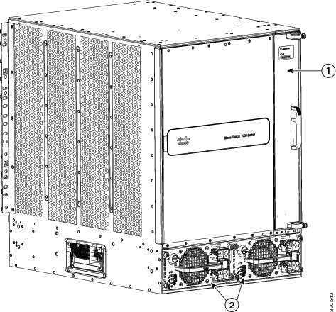
The Cisco Nexus 7009 chassis has 9 slots that allow for one or two supervisor modules and up to seven I/O modules. Additionally, the chassis also holds up to five fabric modules, one fan tray, up to two power supplies, and cable management frames. The chassis also has a front-mount bracket (an alternative center-mount bracket can be ordered) and four positioning handles (two on each side) that you use to position the chassis after you place it on a mechanical lift or bottom-support brackets. Optionally, you can include a door and air intake frame.
Figure 1-2 identifies the standard features on the front and sides of the Cisco Nexus 7009 chassis, and Figure 1-3 identifies the standard features on the rear of the chassis.
Figure 1-2 Standard Hardware Features on the Front and Sides of the Cisco Nexus 7009 Chassis

Figure 1-3 Standard Hardware Features on the Rear of a Cisco Nexus 7009 Chassis
|
|
|
Power supplies (1 or 2)—these modules are a combination of the following: |
Note![]() Figure 1-2 and Figure 1-3 show the Cisco Nexus 7009 chassis as it appears when it is fully configured before including cables for management and network connections. The systems that are not fully configured with the maximum number of supervisor modules, I/O modules, fabric modules, or power supplies have blank panels installed in place of the missing components to maintain the designed airflow for system cooling.
Figure 1-2 and Figure 1-3 show the Cisco Nexus 7009 chassis as it appears when it is fully configured before including cables for management and network connections. The systems that are not fully configured with the maximum number of supervisor modules, I/O modules, fabric modules, or power supplies have blank panels installed in place of the missing components to maintain the designed airflow for system cooling.
The I/O module slots hold one or two of the following types of modules:
–![]() 32-port 1- and 10-Gigabit Ethernet I/O modules (N7K-F132XP-15)
32-port 1- and 10-Gigabit Ethernet I/O modules (N7K-F132XP-15)
–![]() 48-port 1-/10-GBASE-T with XL option (N7K-F248XT-25E)
48-port 1-/10-GBASE-T with XL option (N7K-F248XT-25E)
–![]() 48-port 1-/10-Gigabit SFP+ with XL option and FEX support (N7K-F248XP-25 and N7K-F248XP-25E2)
48-port 1-/10-Gigabit SFP+ with XL option and FEX support (N7K-F248XP-25 and N7K-F248XP-25E2)
–![]() 48-port 1-/10-Gigabit Ethernet SFP/SFP+ (N7K-F348XP-25)
48-port 1-/10-Gigabit Ethernet SFP/SFP+ (N7K-F348XP-25)
–![]() 12-port 40-Gigabit Ethernet QSFP+ (N7K-F312FQ-25)
12-port 40-Gigabit Ethernet QSFP+ (N7K-F312FQ-25)
–![]() 6-port 100-Gigabit Ethernet CPAK (N7K-F306CK-25)
6-port 100-Gigabit Ethernet CPAK (N7K-F306CK-25)
–![]() 48-port 10/100/1000 I/O modules (N7K-M148GT-11)
48-port 10/100/1000 I/O modules (N7K-M148GT-11)
–![]() 48-port 10/100/1000 I/O modules with XL option (N7K-M148GT-11L)
48-port 10/100/1000 I/O modules with XL option (N7K-M148GT-11L)
–![]() 48-port 1-Gigabit Ethernet I/O modules (N7K-M148GS-11)
48-port 1-Gigabit Ethernet I/O modules (N7K-M148GS-11)
–![]() 48-port 1-Gigabit Ethernet I/O modules with XL option (N7K-M148GS-11L)
48-port 1-Gigabit Ethernet I/O modules with XL option (N7K-M148GS-11L)
–![]() 32-port 10-Gigabit Ethernet I/O modules with FEX support (N7K-M132XP-12)
32-port 10-Gigabit Ethernet I/O modules with FEX support (N7K-M132XP-12)
–![]() 32-port 10-Gigabit Ethernet I/O modules with XL option and FEX support (N7K-M132XP-12L)
32-port 10-Gigabit Ethernet I/O modules with XL option and FEX support (N7K-M132XP-12L)
–![]() 8-port 10-Gigabit Ethernet I/O modules with XL option (N7K-M108X2-12L)
8-port 10-Gigabit Ethernet I/O modules with XL option (N7K-M108X2-12L)
–![]() 24-port 10-Gigabit Ethernet I/O modules with XL option and FEX support (N7K-M224XP-23L)
24-port 10-Gigabit Ethernet I/O modules with XL option and FEX support (N7K-M224XP-23L)
–![]() 6-port 40-Gigabit Ethernet I/O modules with XL option (N7K-M206XP-23L)
6-port 40-Gigabit Ethernet I/O modules with XL option (N7K-M206XP-23L)
–![]() 2-port 100-Gigabit Ethernet I/O modules with XL option (N7K-M202XP-23L)
2-port 100-Gigabit Ethernet I/O modules with XL option (N7K-M202XP-23L)
–![]() 48-port 1-/10-Gigabit Ethernet SFP+ (N7K-M348XP-25L)
48-port 1-/10-Gigabit Ethernet SFP+ (N7K-M348XP-25L)
–![]() 24-port 40-Gigabit Ethernet QSFP+ (N7K-M324FQ-25L)
24-port 40-Gigabit Ethernet QSFP+ (N7K-M324FQ-25L)
Note![]() M3-Series I/O modules are not compatible with Sup-1 and Fab-1 modules. M3-Series I/O modules cannot be combined with M1-,F1- or F2-Series I/O modules in the same Cisco Nexus 7009 switch.
M3-Series I/O modules are not compatible with Sup-1 and Fab-1 modules. M3-Series I/O modules cannot be combined with M1-,F1- or F2-Series I/O modules in the same Cisco Nexus 7009 switch.
Note ●![]() Starting with Cisco NX-OS Release 7.3(0)D1(1), the following I/O modules are not supported:
Starting with Cisco NX-OS Release 7.3(0)D1(1), the following I/O modules are not supported:
–![]() 32-port 1- and 10-Gigabit Ethernet I/O modules (N7K-F132XP-15)
32-port 1- and 10-Gigabit Ethernet I/O modules (N7K-F132XP-15)
–![]() 48-port 10/100/1000 I/O modules (N7K-M148GT-11)
48-port 10/100/1000 I/O modules (N7K-M148GT-11)
–![]() 32-port 10-Gigabit Ethernet I/O modules with FEX support (N7K-M132XP-12)
32-port 10-Gigabit Ethernet I/O modules with FEX support (N7K-M132XP-12)
–![]() 48-port 1-Gigabit Ethernet I/O modules (N7K-M148GS-11)
48-port 1-Gigabit Ethernet I/O modules (N7K-M148GS-11)
–![]() 48-port 1-/10-Gigabit SFP+ (N7K-F248XP-25)
48-port 1-/10-Gigabit SFP+ (N7K-F248XP-25)
–![]() 48-port 10/100/1000 with XL option (N7K-M148GT-11L)
48-port 10/100/1000 with XL option (N7K-M148GT-11L)
–![]() 48-port 1-Gigabit Ethernet with XL option (N7K-M148GS-11L)
48-port 1-Gigabit Ethernet with XL option (N7K-M148GS-11L)
–![]() 32-port 10-Gigabit Ethernet with XL option and FEX support (N7K-M132XP-12L)
32-port 10-Gigabit Ethernet with XL option and FEX support (N7K-M132XP-12L)
–![]() 8-port 10-Gigabit Ethernet with XL option (N7K-M108X2-12L)
8-port 10-Gigabit Ethernet with XL option (N7K-M108X2-12L)
You must install the Cisco Nexus 7009 chassis in a two- or four-post 19-inch EIA rack that meets the following specifications:
- Mounting rails that conform to the English universal hole spacing as specified in ANSI/EIA-310-D-1992.
- The minimum vertical rack space is 24.5 inches (62.2 cm) or 14 rack units (RU) for a single chassis installation (15 RU if you use the bottom support rails, which are required for center-mount installations and optional for front-mount installations).
Install the Cisco Nexus 7009 chassis at the lowest possible RU on the rack for stability. If there are other devices in the rack, install the heaviest chassis below the lighter chassis.
Warning![]() Stability hazard. The rack stabilizing mechanism must be in place, or the rack must be bolted to the floor before you slide the unit out for servicing. Failure to stabilize the rack can cause the rack to tip over. Statement 1048
Stability hazard. The rack stabilizing mechanism must be in place, or the rack must be bolted to the floor before you slide the unit out for servicing. Failure to stabilize the rack can cause the rack to tip over. Statement 1048
Cisco Nexus 7010 System
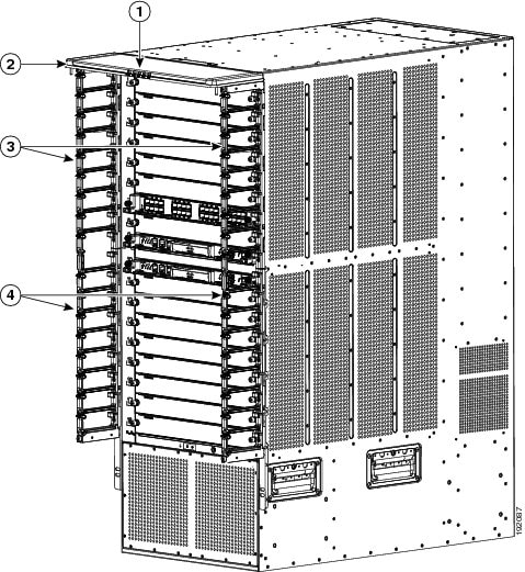
The Cisco Nexus 7010 chassis has 10 slots that allow for two supervisor modules and up to eight I/O modules. Additionally, the chassis holds up to five fabric modules, two system fan trays, two fabric fan trays, up to three power supplies, and cable management frames. The chassis also has mounting brackets and four positioning handles (two on each side) that you use to install the chassis after you position it on a rack. Optionally, you can include an air filter and mid-frame doors.
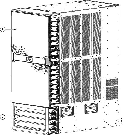
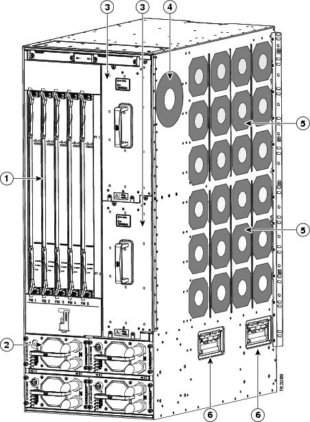
Figure 1-4 identifies the standard features on the front and sides of the Cisco Nexus 7010 chassis, Figure 1-5 identifies the optional features on the front side of the chassis, and Figure 1-6 identifies the standard features on the rear of the chassis.
Figure 1-4 Standard Hardware Features on the Front and Sides of the Cisco Nexus 7010 Chassis
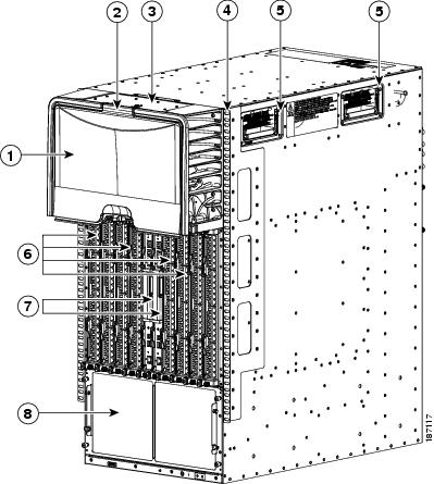
Figure 1-5 Optional Hardware Features on the Front Side of the Cisco Nexus 7010 Chassis
|
|
|
Figure 1-6 Standard Hardware Features on the Back of the Cisco Nexus 7010 Chassis
Note![]() Figure 1-4 and Figure 1-6 show the Cisco Nexus 7000 Series chassis as it appears when it is fully configured before including cables for connections to the Internet and the console. The systems that are not fully configured with the maximum number of supervisor modules, I/O modules, fabric modules, or power supplies have blank filler panels installed in place of the missing components to maintain the designed airflow for system cooling.
Figure 1-4 and Figure 1-6 show the Cisco Nexus 7000 Series chassis as it appears when it is fully configured before including cables for connections to the Internet and the console. The systems that are not fully configured with the maximum number of supervisor modules, I/O modules, fabric modules, or power supplies have blank filler panels installed in place of the missing components to maintain the designed airflow for system cooling.
The I/O module slots hold one or two of the following types of modules:
–![]() 32-port 1- and 10-Gigabit Ethernet I/O modules (N7K-F132XP-15)
32-port 1- and 10-Gigabit Ethernet I/O modules (N7K-F132XP-15)
–![]() 48-port 1-/10-GBASE-T with XL option (N7K-F248XT-25E)
48-port 1-/10-GBASE-T with XL option (N7K-F248XT-25E)
–![]() 48-port 1-/10-Gigabit SFP+ with XL option and FEX support (N7K-F248XP-25 and N7K-F248XP-25E3)
48-port 1-/10-Gigabit SFP+ with XL option and FEX support (N7K-F248XP-25 and N7K-F248XP-25E3)
–![]() 48-port 1-/10-Gigabit Ethernet SFP/SFP+ (N7K-F348XP-25)
48-port 1-/10-Gigabit Ethernet SFP/SFP+ (N7K-F348XP-25)
–![]() 12-port 40-Gigabit Ethernet QSFP+ (N7K-F312FQ-25)
12-port 40-Gigabit Ethernet QSFP+ (N7K-F312FQ-25)
–![]() 6-port 100-Gigabit Ethernet CPAK (N7K-F306CK-25)
6-port 100-Gigabit Ethernet CPAK (N7K-F306CK-25)
–![]() 48-port 10/100/1000 I/O modules (N7K-M148GT-11)
48-port 10/100/1000 I/O modules (N7K-M148GT-11)
–![]() 48-port 10/100/1000 I/O modules with XL option (N7K-M148GT-11L)
48-port 10/100/1000 I/O modules with XL option (N7K-M148GT-11L)
–![]() 48-port 1-Gigabit Ethernet I/O modules (N7K-M148GS-11)
48-port 1-Gigabit Ethernet I/O modules (N7K-M148GS-11)
–![]() 48-port 1-Gigabit Ethernet I/O modules with XL option (N7K-M148GS-11L)
48-port 1-Gigabit Ethernet I/O modules with XL option (N7K-M148GS-11L)
–![]() 32-port 10-Gigabit Ethernet I/O modules with FEX support (N7K-M132XP-12)
32-port 10-Gigabit Ethernet I/O modules with FEX support (N7K-M132XP-12)
–![]() 32-port 10-Gigabit Ethernet I/O modules with XL option and FEX support (N7K-M132XP-12L)
32-port 10-Gigabit Ethernet I/O modules with XL option and FEX support (N7K-M132XP-12L)
–![]() 8-port 10-Gigabit Ethernet I/O modules with XL option (N7K-M108X2-12L)
8-port 10-Gigabit Ethernet I/O modules with XL option (N7K-M108X2-12L)
–![]() 24-port 10-Gigabit Ethernet I/O modules with XL option and FEX support (N7K-M224XP-23L)
24-port 10-Gigabit Ethernet I/O modules with XL option and FEX support (N7K-M224XP-23L)
–![]() 6-port 40-Gigabit Ethernet I/O modules with XL option (N7K-M206XP-23L)
6-port 40-Gigabit Ethernet I/O modules with XL option (N7K-M206XP-23L)
–![]() 2-port 100-Gigabit Ethernet I/O modules with XL option (N7K-M202XP-23L)
2-port 100-Gigabit Ethernet I/O modules with XL option (N7K-M202XP-23L)
–![]() 48-port 1-/10-Gigabit Ethernet SFP+ (N7K-M348XP-25L)
48-port 1-/10-Gigabit Ethernet SFP+ (N7K-M348XP-25L)
–![]() 24-port 40-Gigabit Ethernet QSFP+ (N7K-M324FQ-25L)
24-port 40-Gigabit Ethernet QSFP+ (N7K-M324FQ-25L)
Note![]() M3-Series I/O modules are not compatible with Sup-1 and Fab-1 modules. M3-Series I/O modules cannot be combined with M1-,F1- or F2-Series I/O modules in the same Cisco Nexus 7010 switch.
M3-Series I/O modules are not compatible with Sup-1 and Fab-1 modules. M3-Series I/O modules cannot be combined with M1-,F1- or F2-Series I/O modules in the same Cisco Nexus 7010 switch.
Note ●![]() Starting with Cisco NX-OS Release 7.3(0)D1(1), the following I/O modules are not supported:
Starting with Cisco NX-OS Release 7.3(0)D1(1), the following I/O modules are not supported:
–![]() 32-port 1- and 10-Gigabit Ethernet I/O modules (N7K-F132XP-15)
32-port 1- and 10-Gigabit Ethernet I/O modules (N7K-F132XP-15)
–![]() 48-port 10/100/1000 I/O modules (N7K-M148GT-11)
48-port 10/100/1000 I/O modules (N7K-M148GT-11)
–![]() 32-port 10-Gigabit Ethernet I/O modules with FEX support (N7K-M132XP-12)
32-port 10-Gigabit Ethernet I/O modules with FEX support (N7K-M132XP-12)
–![]() 48-port 1-Gigabit Ethernet I/O modules (N7K-M148GS-11)
48-port 1-Gigabit Ethernet I/O modules (N7K-M148GS-11)
–![]() 48-port 1-/10-Gigabit SFP+ (N7K-F248XP-25)
48-port 1-/10-Gigabit SFP+ (N7K-F248XP-25)
–![]() 48-port 10/100/1000 with XL option (N7K-M148GT-11L)
48-port 10/100/1000 with XL option (N7K-M148GT-11L)
–![]() 48-port 1-Gigabit Ethernet with XL option (N7K-M148GS-11L)
48-port 1-Gigabit Ethernet with XL option (N7K-M148GS-11L)
–![]() 32-port 10-Gigabit Ethernet with XL option and FEX support (N7K-M132XP-12L)
32-port 10-Gigabit Ethernet with XL option and FEX support (N7K-M132XP-12L)
–![]() 8-port 10-Gigabit Ethernet with XL option (N7K-M108X2-12L)
8-port 10-Gigabit Ethernet with XL option (N7K-M108X2-12L)
You must install the Cisco Nexus 7010 system chassis in a four-post 19-inch EIA rack that meets the following specifications:
- Mounting rails that conform to the English universal hole spacing as specified in ANSI/EIA-310-D-1992.
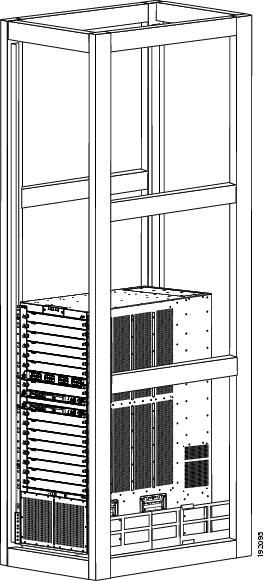
- The minimum vertical rack space is 36.75 inches (93.3 cm) or 21 rack units (RU) for a single chassis installation and 73.5 inches (186.6 cm) or 42 rack units for a dual-chassis installation. We recommend that you use a 45 RU rack for a dual-chassis installation.
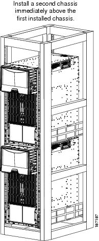
If you install one chassis, install it at the lowest possible RU on the rack for stability, as shown in Figure 1-7. If you install two chassis in the same rack, install the bottom chassis first and then install the other chassis on top as shown in Figure 1-8.
Warning![]() Stability hazard. The rack stabilizing mechanism must be in place, or the rack must be bolted to the floor before you slide the unit out for servicing. Failure to stabilize the rack can cause the rack to tip over. Statement 1048
Stability hazard. The rack stabilizing mechanism must be in place, or the rack must be bolted to the floor before you slide the unit out for servicing. Failure to stabilize the rack can cause the rack to tip over. Statement 1048
Figure 1-7 One Cisco Nexus 7010 Chassis Installed in a Four-Post Rack
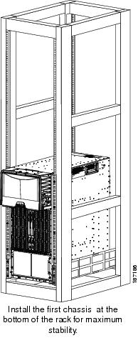
Figure 1-8 Two Cisco Nexus 7010 Chassis Installed in a Four-Post Rack
Cisco Nexus 7018 System
The Cisco Nexus 7018 chassis has 18 slots that allow for two supervisor modules and up to 16 I/O modules. The chassis also holds up to five fabric modules, two fan trays, up to four power supplies, and a cable management system. The chassis also has a mounting bracket and four positioning handles (two on each side) that you use to install the chassis after you position it on a rack. Optionally, you can include a front door to protect the I/O cable connections.
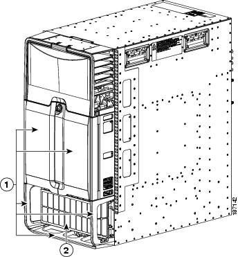
Figure 1-9 identifies the standard features on the front and sides of the Cisco Nexus 7018 chassis, Figure 1-10 identifies the components of the cable management system, Figure 1-11 identifies the optional feature on the front side of the chassis, and Figure 1-12 identifies the standard features on the rear of the chassis.
Figure 1-9 Standard Hardware Features on the Front and Sides of the Cisco Nexus 7018 Chassis
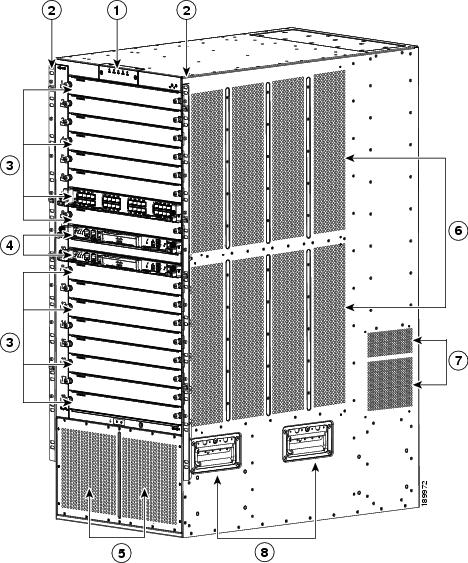
Figure 1-10 Cable Management System for the Cisco Nexus 7018 Chassis
|
|
System status LEDs (these LEDs show the system status displayed by the chassis LEDs) |
|
|
|
|
|
Figure 1-11 Optional Front Door for the Cisco Nexus 7018 Chassis
|
|
|
Figure 1-12 Standard Hardware Features on the Back of the Cisco Nexus 7018 Chassis
Note![]() Figure 1-9 and Figure 1-12 show the Cisco Nexus 7018 chassis as it appears when it is fully configured before including cables for connections to the Internet and the console. The systems that are not fully configured with the maximum number of supervisor modules, I/O modules, fabric modules, or power supplies have blank panels installed in place of the missing components to maintain the designed airflow for system cooling.
Figure 1-9 and Figure 1-12 show the Cisco Nexus 7018 chassis as it appears when it is fully configured before including cables for connections to the Internet and the console. The systems that are not fully configured with the maximum number of supervisor modules, I/O modules, fabric modules, or power supplies have blank panels installed in place of the missing components to maintain the designed airflow for system cooling.
The I/O module slots hold one or two of the following types of modules:
–![]() 32-port 1- and 10-Gigabit Ethernet I/O modules (N7K-F132XP-15)
32-port 1- and 10-Gigabit Ethernet I/O modules (N7K-F132XP-15)
–![]() 48-port 1-/10-GBASE-T with XL option (N7K-F248XT-25E)
48-port 1-/10-GBASE-T with XL option (N7K-F248XT-25E)
–![]() 48-port 1-/10-Gigabit SFP+ with XL option and FEX support (N7K-F248XP-25 and N7K-F248XP-25E4)
48-port 1-/10-Gigabit SFP+ with XL option and FEX support (N7K-F248XP-25 and N7K-F248XP-25E4)
–![]() 48-port 1-/10-Gigabit Ethernet SFP/SFP+ (N7K-F348XP-25)
48-port 1-/10-Gigabit Ethernet SFP/SFP+ (N7K-F348XP-25)
–![]() 12-port 40-Gigabit Ethernet QSFP+ (N7K-F312FQ-25)
12-port 40-Gigabit Ethernet QSFP+ (N7K-F312FQ-25)
–![]() 6-port 100-Gigabit Ethernet CPAK (N7K-F306CK-25)
6-port 100-Gigabit Ethernet CPAK (N7K-F306CK-25)
–![]() 48-port 10/100/1000 I/O modules (N7K-M148GT-11)
48-port 10/100/1000 I/O modules (N7K-M148GT-11)
–![]() 48-port 10/100/1000 I/O modules with XL option (N7K-M148GT-11L)
48-port 10/100/1000 I/O modules with XL option (N7K-M148GT-11L)
–![]() 48-port 1-Gigabit Ethernet I/O modules (N7K-M148GS-11)
48-port 1-Gigabit Ethernet I/O modules (N7K-M148GS-11)
–![]() 48-port 1-Gigabit Ethernet I/O modules with XL option (N7K-M148GS-11L)
48-port 1-Gigabit Ethernet I/O modules with XL option (N7K-M148GS-11L)
–![]() 32-port 10-Gigabit Ethernet I/O modules with FEX support (N7K-M132XP-12)
32-port 10-Gigabit Ethernet I/O modules with FEX support (N7K-M132XP-12)
–![]() 32-port 10-Gigabit Ethernet I/O modules with XL option and FEX support (N7K-M132XP-12L)
32-port 10-Gigabit Ethernet I/O modules with XL option and FEX support (N7K-M132XP-12L)
–![]() 8-port 10-Gigabit Ethernet I/O modules with XL option (N7K-M108X2-12L)
8-port 10-Gigabit Ethernet I/O modules with XL option (N7K-M108X2-12L)
–![]() 24-port 10-Gigabit Ethernet I/O modules with XL option and FEX support (N7K-M224XP-23L)
24-port 10-Gigabit Ethernet I/O modules with XL option and FEX support (N7K-M224XP-23L)
–![]() 6-port 40-Gigabit Ethernet I/O modules with XL option (N7K-M206XP-23L)
6-port 40-Gigabit Ethernet I/O modules with XL option (N7K-M206XP-23L)
–![]() 2-port 100-Gigabit Ethernet I/O modules with XL option (N7K-M202XP-23L)
2-port 100-Gigabit Ethernet I/O modules with XL option (N7K-M202XP-23L)
–![]() 48-port 1-/10-Gigabit Ethernet SFP+ (N7K-M348XP-25L)
48-port 1-/10-Gigabit Ethernet SFP+ (N7K-M348XP-25L)
–![]() 24-port 40-Gigabit Ethernet QSFP+ (N7K-M324FQ-25L)
24-port 40-Gigabit Ethernet QSFP+ (N7K-M324FQ-25L)
Note![]() M3-Series I/O modules are not compatible with Sup-1 and Fab-1 modules. M3-Series I/O modules cannot be combined with M1-,F1- or F2-Series I/O modules in the same Cisco Nexus 7018 switch.
M3-Series I/O modules are not compatible with Sup-1 and Fab-1 modules. M3-Series I/O modules cannot be combined with M1-,F1- or F2-Series I/O modules in the same Cisco Nexus 7018 switch.
Note ●![]() Starting with Cisco NX-OS Release 7.3(0)D1(1), the following I/O modules are not supported:
Starting with Cisco NX-OS Release 7.3(0)D1(1), the following I/O modules are not supported:
–![]() 32-port 1- and 10-Gigabit Ethernet I/O modules (N7K-F132XP-15)
32-port 1- and 10-Gigabit Ethernet I/O modules (N7K-F132XP-15)
–![]() 48-port 10/100/1000 I/O modules (N7K-M148GT-11)
48-port 10/100/1000 I/O modules (N7K-M148GT-11)
–![]() 32-port 10-Gigabit Ethernet I/O modules with FEX support (N7K-M132XP-12)
32-port 10-Gigabit Ethernet I/O modules with FEX support (N7K-M132XP-12)
–![]() 48-port 1-Gigabit Ethernet I/O modules (N7K-M148GS-11)
48-port 1-Gigabit Ethernet I/O modules (N7K-M148GS-11)
–![]() 48-port 1-/10-Gigabit SFP+ (N7K-F248XP-25)
48-port 1-/10-Gigabit SFP+ (N7K-F248XP-25)
–![]() 48-port 10/100/1000 with XL option (N7K-M148GT-11L)
48-port 10/100/1000 with XL option (N7K-M148GT-11L)
–![]() 48-port 1-Gigabit Ethernet with XL option (N7K-M148GS-11L)
48-port 1-Gigabit Ethernet with XL option (N7K-M148GS-11L)
–![]() 32-port 10-Gigabit Ethernet with XL option and FEX support (N7K-M132XP-12L)
32-port 10-Gigabit Ethernet with XL option and FEX support (N7K-M132XP-12L)
–![]() 8-port 10-Gigabit Ethernet with XL option (N7K-M108X2-12L)
8-port 10-Gigabit Ethernet with XL option (N7K-M108X2-12L)
You can insert a maximum of ten 24-port 40-Gigabit Ethernet QSFP+ (N7K-M324FQ-25L) I/O modules in the Cisco Nexus 7018 switch. This I/O module uses 96 VQI per slot. The maximum VQI of a Cisco Nexus 7018 switch is 1024 and a total of eleven 24-port 40-Gigabit Ethernet QSFP+ I/0 modules will require 1056 VQI. In such a scenario, the eleventh I/O module will attempt to come online 3 times and then will get powered down. During a reload of a switch with eleven 24-port 40-Gigabit Ethernet QSFP+ I/0 modules, the I/O module that comes up last will be powered down.
You must install the Cisco Nexus 7018 chassis in a four-post 19-inch EIA rack that meets the following specifications:
- Mounting rails that conform to the English universal hole spacing as specified in ANSI/EIA-310-D-1992.
- The minimum vertical rack space is 43.75 inches (111.1 cm) or 25 rack units (RU) for a single chassis installation and 87.5 inches (222.2 cm).
Install the Cisco Nexus 7018 chassis at the lowest possible RU on the rack for stability, as shown in Figure 1-13. If there is another device in the rack, install the heaviest one at the bottom.
Warning![]() Stability hazard. The rack stabilizing mechanism must be in place, or the rack must be bolted to the floor before you slide the unit out for servicing. Failure to stabilize the rack can cause the rack to tip over. Statement 1048
Stability hazard. The rack stabilizing mechanism must be in place, or the rack must be bolted to the floor before you slide the unit out for servicing. Failure to stabilize the rack can cause the rack to tip over. Statement 1048
Figure 1-13 Cisco Nexus 7018 Chassis Installed in a Four-Post Rack
Preparing the Site
Warning![]() Installation of the equipment must comply with local and national electrical codes. Statement 1074
Installation of the equipment must comply with local and national electrical codes. Statement 1074
Before you can install a Cisco Nexus 7000 Series system, you must prepare the site for the installation. You must make sure that the altitude, temperature, humidity, air quality, airflow, electromagnetic and radio frequency interference, floor structure, power, and earth grounding of the installation site all meet the requirements of the Cisco Nexus 7000 Series system that you are installing. In addition, you must set up a rack or cabinet that can hold the number of chassis that you are installing. To see the general requirements for this system, see Appendix A, “Technical Specifications.” To see detailed information about preparing the data center for the installation, see the Cisco Nexus 7000 Series Site Preparation Guide.
Safety Guidelines
Warning![]() Only trained and qualified personnel should be allowed to install, replace, or service this equipment. Statement 1030
Only trained and qualified personnel should be allowed to install, replace, or service this equipment. Statement 1030
The prerequisites listed for any procedure are required conditions that you must verify before you start that procedure. If the prerequisites have not been met, you must satisfy those requirements before carrying out the procedure.
Safety warnings appear in this publication wherever procedures present conditions that could endanger you or others installing this system. Adhering to these warnings and following their recommended actions are required actions for these procedures. For regulatory compliance and safety information on these warnings, see the Cisco Nexus 7000 Series Regulatory Compliance and Safety Information document.
Installation and Connection Guidelines
After you fully prepare the site as specified in the Cisco Nexus 7000 Series Site Preparation Guide, install a two-post 19-inch EIA rack for Cisco Nexus 7004 and 7009 chassis or a four-post 19-inch EIA rack for all chassis. To install the system, you must make sure that you have the proper mounting brackets (front-mount or center-mount brackets) installed on the chassis, move the chassis to the rack, elevate it to the lowest possible RU for that chassis, and fasten the chassis to the rack. With the chassis fastened to the rack, you can ground the chassis, install its cable management frames, install the optional door and optional air filter, and connect the switch to the console and network. For detailed instructions on installing a Cisco Nexus 7000 Series switch, see the following chapters:
- Chapter 2, “Installing a Cisco Nexus 7004 Chassis”
- Chapter 2, “Installing a Cisco Nexus 7004 Chassis”
- Chapter 3, “Installing a Cisco Nexus 7009 Chassis”
- Chapter 4, “Installing a Cisco Nexus 7010 Chassis”
- Chapter 5, “Installing a Cisco Nexus 7018 Chassis”
- Chapter 6, “Installing Power Supplies”
For detailed instructions on connecting the switch to the console and network, see Chapter7, “Connecting the Cisco Nexus 7000 Series Switch to the Network”

If you are replacing Fabric 1 modules with Fabric 2 modules (Cisco Nexus 7010 and 7018 models only), you must replace all of the Fabric 1 modules with Fabric 2 modules or the Fabric 2 modules will perform like Fabric 1 modules. If you power up a switch with both Fabric 1 and Fabric 2 modules installed, only the Fabric 2 modules will power up.
Note![]() The Cisco NX-OS software may require 8 GB of memory, depending on the software version you use and the software features that you enable. If your switch has Supervisor 1 modules with only 4 GB of memory, then you might need to upgrade the modules to 8 GB of memory by using the 8 GB supervisor upgrade kit (N7K-SUP1-8GBUPG=). This upgrade is not needed for switches that have at least 8 GB of memory (which includes Supervisor 1 modules with 8 GB and all Supervisor 2 and Supervisor 2E modules). To verify the amount of memory installed in the supervisor modules or to upgrade the memory, see the “Upgrading Memory for Supervisor 1 Modules” section.
The Cisco NX-OS software may require 8 GB of memory, depending on the software version you use and the software features that you enable. If your switch has Supervisor 1 modules with only 4 GB of memory, then you might need to upgrade the modules to 8 GB of memory by using the 8 GB supervisor upgrade kit (N7K-SUP1-8GBUPG=). This upgrade is not needed for switches that have at least 8 GB of memory (which includes Supervisor 1 modules with 8 GB and all Supervisor 2 and Supervisor 2E modules). To verify the amount of memory installed in the supervisor modules or to upgrade the memory, see the “Upgrading Memory for Supervisor 1 Modules” section.
Managing the System Hardware
After the Cisco Nexus 7000 Series system is installed and operating, you can use the Cisco NX-OS operating system to manage the system hardware. These management functions include displaying system and module information, setting the power supply modes, and managing module functions. For more information about these functions, see Chapter8, “Managing the Switch Hardware”
Replacing Components
While the Cisco Nexus 7000 Series system is operational, you can replace any one of the following components if they are redundant:
- Power supply
- Supervisor module
- Fabric module (Cisco Nexus 7009, 7010, and 7018 models only)
- I/O modules
- Fan trays
For detailed information on replacing these components, see Chapter10, “Installing or Replacing Components”
 Feedback