- Preface
- Overview
- Installing a Cisco Nexus 7004 Switch
- Installing a Cisco Nexus 7009 Chassis
- Installing a Cisco Nexus 7010 Chassis
- Installing a Cisco Nexus 7018 Chassis
- Installing Power Supply Units
- Connecting the Cisco Nexus 7000 Switch to the Network
- Managing system hardware
- Troubleshooting
- Replacement Procedures
- Technical Specifications
- Transceiver and Module Connectors
- Cisco Nexus 7000 Series Accessory Kit Contents
- Chassis and Module LEDs
- Repacking the Nexus 7000 Series Switch for Shipment
- Site Preparation and Maintenance Records
- Required Tools and Equipment
- Installing Power Supplies
- Connecting an AC and HVAC/HVDC Power Supply to AC Power Sources
- Connecting a DC and HVAC/HVDC Power Supply to DC Power Sources
Installing Power Supplies
This chapter describes how to install AC and DC power supplies in any Cisco Nexus 7000 Series chassis. You can install the HVAC/HVDC power supplies only on the Cisco Nexus 7004 chassis. The AC power supplies convert the AC power from your facility to DC power for use in the chassis; the DC power supplies take DC power from your facility for use in the chassis. In the same chassis, you can install AC power supplies, DC power supplies, or a combination of AC and DC power supplies, but the power supplies must be the right size for the power supply slots (you cannot mix the smaller power supplies designed for the Cisco Nexus 7004 switch with the larger units designed for the Cisco Nexus 7009, 7010, and 7018 switches). In a Cisco Nexus 7004 chassis, you can install AC power supplies, DC power supplies or HVAC/HVDC power supplies or a combination of AC, DC and HVAC/HVDC power supplies.
For information on managing power modes, see the “Power Supply Configuration Modes” section.
Required Tools and Equipment
Each power supply comes with its own ground lug, ground lug screws, and power cords.

Note![]() Each power supply, except for the 3-kW DC power supply, comes with the required power cords for your country.
Each power supply, except for the 3-kW DC power supply, comes with the required power cords for your country.
To mount and install power supplies, you need the following additional tools and equipment:
- Number 1 Phillips-head screwdriver with torque capability
- Nut driver attachment for screwdriver or ratchet wrench with torque capability (used only for DC power supplies)
- Wire-stripping tool
- Crimping tool
- For 3-kW DC power supplies, you need four power cables sized to reach the DC power source or power interface unit (PIU)
- Grounding wire—This wire should be sized to meet local and national installation requirements. For U.S. installations, you must use a 6 AWG copper conductor. For installations outside the U.S., consult your local and national electrical codes. The length of the grounding wire depends on the proximity of the switch to proper grounding facilities.
Installing Power Supplies
You can install two or more power supplies in each Cisco Nexus 7000 Series chassis. If you leave any power supply slots empty, you must install a blank filler plate in those slots to maintain the designed airflow. Table 6-1 lists the quantities and types of power supplies that you can install in each chassis.
Note![]() For the Cisco Nexus 7004 switches, the chassis ships with their power supplies already installed. For the Cisco Nexus 7009, 7010, and 7018 switches, the power supplies ship with the chassis but are boxed separately, so you must install them using the instructions provided in this chapter.
For the Cisco Nexus 7004 switches, the chassis ships with their power supplies already installed. For the Cisco Nexus 7009, 7010, and 7018 switches, the power supplies ship with the chassis but are boxed separately, so you must install them using the instructions provided in this chapter.
When you install AC and DC power supplies in a Cisco Nexus 7000 Series chassis, you mount them similarly, but you ground them differently. For an AC and HVAC/HVDC power supply, you automatically ground it when you connect it to the AC or HVAC/HVDC power source because the power cable includes a ground connection. For a 6-kW DC power supply, you must connect the power supply to the earth ground before you connect it to the DC power source. For the 3-kW DC power supply, you do not connect it directly to the earth ground because it is grounded through the chassis.
To mount a power supply in a Cisco Nexus 7000 Series chassis, follow these steps:
Step 1![]() Ensure that the power switch on the front of the power supply is set to standby (labelled as STBY or 0) and that the power supply is not connected to any power sources.
Ensure that the power switch on the front of the power supply is set to standby (labelled as STBY or 0) and that the power supply is not connected to any power sources.
Step 2![]() Grasp the handle on the power supply with one hand, place the other hand under the power supply, and orient its back end to an open power supply bay.
Grasp the handle on the power supply with one hand, place the other hand under the power supply, and orient its back end to an open power supply bay.
Step 3![]() Slide the unit all the way into the power supply bay until one of the following situations occurs:
Slide the unit all the way into the power supply bay until one of the following situations occurs:
- For the Cisco Nexus 7004 chassis, the release latch on the front of the power supply clicks and prevents you from moving the power supply in or out of the chassis. This action completes the mounting of the power supply on this chassis.
- For the Cisco Nexus 7009, 7010, or 7018 chassis, the front of the power supply is touching the front of the chassis and the four captive screws on the front of the power supply are aligned with four screw holes in the chassis.
Step 4![]() For the Cisco Nexus 7009, 7010, or 7018 chassis, screw each of the four captive screws into the chassis and tighten them to 8 in-lb (0.9 N·m). This action completes the mounting of the power supply on this chassis.
For the Cisco Nexus 7009, 7010, or 7018 chassis, screw each of the four captive screws into the chassis and tighten them to 8 in-lb (0.9 N·m). This action completes the mounting of the power supply on this chassis.
Note![]() If you do not have enough power supplies to fill all of the power supply bays, cover each empty power supply bay with a blank filler plate and secure it by screwing in its captive screws to 8 in-lb (0.9 N·m).
If you do not have enough power supplies to fill all of the power supply bays, cover each empty power supply bay with a blank filler plate and secure it by screwing in its captive screws to 8 in-lb (0.9 N·m).
If you are installing an AC power supply, you must now connect it to an AC power source (see the “Connecting an AC and HVAC/HVDC Power Supply to AC Power Sources” section and “Connecting a 3.5-kW HVAC/HVDC Power Supply to AC Power Sources” section). The power supply will be automatically grounded through its power cable.
If you are installing a 3-kW DC power supply, you must connect the power supply to the DC power source (see the “Connecting a DC and HVAC/HVDC Power Supply to DC Power Sources” section). You do not need to connect the 3-kW DC power supply directly to an earth ground because it is grounded through the chassis. You are ready to connect the power supply to a DC power source as explained in the “Connecting a 3-kW DC Power Supply Directly to DC Power Sources” section.
If you are installing a 6-kW DC power supply, you must ground the power supply (see the “Grounding a 6-kW DC Power Supply” section) before you connect the power supply to the DC power source.
Connecting an AC and HVAC/HVDC Power Supply to AC Power Sources
If you are powering your Cisco Nexus 7000 Series switch with 3-,3.5-, 6-, or 7.5-kW AC power supplies, you must connect those power supplies to an AC power source. When you connect the power cable to the AC power grid and the power supply, the power supply is automatically grounded through this cable.
Before you connect the power supplies to their power sources, you must have already connected the chassis to the earth ground. If the chassis is not yet grounded, see the following sections:
- To ground a Cisco Nexus 7004 chassis, see the “Grounding the Cisco Nexus 7004 Chassis” section.
- To ground a Cisco Nexus 7009 chassis, see the “Grounding the Cisco Nexus 7009 Chassis” section.
- To ground a Cisco Nexus 7010 chassis, see the “Grounding the Cisco Nexus 7010 Chassis” section.
- To ground a Cisco Nexus 7018 chassis, see the “Grounding the Cisco Nexus 7018 Chassis” section.
Note![]() When you plug in an AC power supply to its power source, you automatically ground the power supply through its power cable. For additional grounding protection for the rest of the chassis and its modules, you must ground the chassis before installing its modules.
When you plug in an AC power supply to its power source, you automatically ground the power supply through its power cable. For additional grounding protection for the rest of the chassis and its modules, you must ground the chassis before installing its modules.
You connect the AC power supplies differently as follows:
- For a 3-kW or a 3.5-kW HVAC/HVDC power supply, you connect one power cable to the power supply and one AC power source. For power redundancy, you connect multiple power supplies to one or more power sources in the following ways:
–![]() For combined power mode or power supply redundancy mode, you connect all of the power supplies in the same chassis to the same power source.
For combined power mode or power supply redundancy mode, you connect all of the power supplies in the same chassis to the same power source.
–![]() For input source redundancy mode or full redundancy mode, you connect half of the power supplies in the chassis to one power source and the other half to another power source.
For input source redundancy mode or full redundancy mode, you connect half of the power supplies in the chassis to one power source and the other half to another power source.
- For a 6-kW AC power supply, you connect one or two power cables to the power supply and one or two AC power sources. For power redundancy, you connect the power cables for each power supply to power sources in the following ways:
–![]() For combined power mode, you connect one or both power cables to the same AC power source.
For combined power mode, you connect one or both power cables to the same AC power source.
–![]() For power-supply redundancy mode, you connect both power cables to the same AC power source and you have one more power supply than required to power the modules in the chassis.
For power-supply redundancy mode, you connect both power cables to the same AC power source and you have one more power supply than required to power the modules in the chassis.
–![]() For input-source redundancy mode, you connect the two power cables to different power sources.
For input-source redundancy mode, you connect the two power cables to different power sources.
–![]() For full redundancy mode, you connect the two power cables to different power sources and you have one more power supply than required to power the modules in the chassis.
For full redundancy mode, you connect the two power cables to different power sources and you have one more power supply than required to power the modules in the chassis.
- For a 7.5-kW AC power supply, you connect the two installed power cables to one or two AC power sources. For power redundancy, you connect the power cables for each power supply in the following ways:
–![]() For combined power mode, you connect one or both power cables to the same AC power source.
For combined power mode, you connect one or both power cables to the same AC power source.
–![]() For power-supply redundancy mode, you connect both power cables to the same AC power source and you have one more power supply than required to power the modules in the chassis.
For power-supply redundancy mode, you connect both power cables to the same AC power source and you have one more power supply than required to power the modules in the chassis.
–![]() For input-source redundancy mode, you connect the two power cables to different power sources.
For input-source redundancy mode, you connect the two power cables to different power sources.
–![]() For full redundancy mode, you connect the two power cables to different power sources and you have one more power supply than required to power the modules in the chassis.
For full redundancy mode, you connect the two power cables to different power sources and you have one more power supply than required to power the modules in the chassis.
Note![]() The 3- and 6-kW power supply cables are shipped in the system accessory kit, and the 7.5-kW power supply cables are permanently attached to those power supplies. Check the power cables with the list of available power cables in the accessory kit for the chassis that you ordered (see Appendix C, “Accessory Kits Contents”). If you do not have the correct cables, contact Cisco TAC.
The 3- and 6-kW power supply cables are shipped in the system accessory kit, and the 7.5-kW power supply cables are permanently attached to those power supplies. Check the power cables with the list of available power cables in the accessory kit for the chassis that you ordered (see Appendix C, “Accessory Kits Contents”). If you do not have the correct cables, contact Cisco TAC.

Warning![]() Read the installation instructions before connecting the system to the power source. Statement 1004
Read the installation instructions before connecting the system to the power source. Statement 1004
This section includes the following topics:
- Prerequisites for Connecting AC Power Supplies to AC Power Sources
- Connecting a 3-kW AC Power Supply to AC Power Sources
- Connecting a 3.5-kW HVAC/HVDC Power Supply to AC Power Sources
- Connecting a 6-kW AC Power Supply to AC Power Sources
- Connecting a 7.5-kW AC Power Supply to AC Power Sources
Prerequisites for Connecting AC Power Supplies to AC Power Sources
Before you connect the power supplies to AC power sources, you must mount the power supplies in the chassis, and you must make sure that the appropriate AC power source receptacles are located close enough to the power supplies so that the power cords can connect the power supplies to the power sources. For North American installations of 3-kW or 6-kW AC power supplies, you must have one or two 20-A rated, 110V or 220V circuits. For North American installations of 7.5-kW power supplies, you must have one or two 30-A rated, 220-V AC circuits. For international installations, you must size the circuits by local and national codes. If you are using the input source redundancy mode, you must have at least two circuits.
Connecting a 3-kW AC Power Supply to AC Power Sources
The 3-kW AC power supply ships with one power cable that you must attach to the power supply and its AC power source. To configure power supply redundancy mode, input source redundancy mode, or full redundancy mode, you connect at least two power supplies to one or two AC power sources.
To connect a 3-kW AC power supply to one or more power sources, follow these steps:
Step 1![]() Ensure that the power supply switch located on the front of the power supply is set at standby (labelled as 0).
Ensure that the power supply switch located on the front of the power supply is set at standby (labelled as 0).
Step 2![]() Plug one AC power cable into the power supply, and pull down the retention clip over the plug on the power cable.
Plug one AC power cable into the power supply, and pull down the retention clip over the plug on the power cable.
Step 3![]() Plug the other end of the power cable into a AC power source supplied by the data center.
Plug the other end of the power cable into a AC power source supplied by the data center.
Note![]() If you are using the combined power mode or power supply redundancy, you connect the power cables to the same 20-A circuit. If you are using the input source redundancy mode or full redundancy mode, you connect half of the power cables to one AC power source and the other half to another AC power source.
If you are using the combined power mode or power supply redundancy, you connect the power cables to the same 20-A circuit. If you are using the input source redundancy mode or full redundancy mode, you connect half of the power cables to one AC power source and the other half to another AC power source.
Warning![]() Take care when connecting units to the supply circuit so that wiring is not overloaded. Statement 1018
Take care when connecting units to the supply circuit so that wiring is not overloaded. Statement 1018
Warning![]() This product relies on the building’s installation for short-circuit (overcurrent) protection. Ensure that the protective device is rated not greater than:
This product relies on the building’s installation for short-circuit (overcurrent) protection. Ensure that the protective device is rated not greater than:
250V, 20 A
Statement 1005
Step 4![]() Turn the power supply switch from standby to on (from 0 to 1 as labelled on the power switch).
Turn the power supply switch from standby to on (from 0 to 1 as labelled on the power switch).
Step 5![]() Verify that the power supply is receiving AC power and outputting DC power by making sure that the INPUT and OUTPUT power supply LEDs are lit and the FAULT LED is not lit or flashing. For an explanation of all the power supply LEDs and the conditions that they indicate, see Table D-6.
Verify that the power supply is receiving AC power and outputting DC power by making sure that the INPUT and OUTPUT power supply LEDs are lit and the FAULT LED is not lit or flashing. For an explanation of all the power supply LEDs and the conditions that they indicate, see Table D-6.
Note![]() When you first activate the power supply, you can verify the functionality of the LEDs by checking that each LED turns on for a couple of seconds.
When you first activate the power supply, you can verify the functionality of the LEDs by checking that each LED turns on for a couple of seconds.
If the Fault LED is flashing red, turn the power switch to standby (labelled as 0), check the AC power connections on the power supply and the AC power source, and then turn the power switch back on (labelled as 1). The Input and Output LEDs for the connected power supplies should be green and the Fault LED should be off.
Connecting a 3.5-kW HVAC/HVDC Power Supply to AC Power Sources
The 3.5-kW HVAC/HVDC power supply ships with one power cable that you must attach to the power supply and its AC power source.
To connect a 3.5-kW HVAC/HVDC power supply to a power source, follow these steps:
Step 1![]() Ensure that the power supply switch located on the front of the power supply is set at standby (labelled as 0).
Ensure that the power supply switch located on the front of the power supply is set at standby (labelled as 0).
Step 2![]() Plug the AC power cable into the power supply. The built-in latch secures the power cable to the power supply. You can disconnect the power cable from the power supply by pressing the release button on the power cable.
Plug the AC power cable into the power supply. The built-in latch secures the power cable to the power supply. You can disconnect the power cable from the power supply by pressing the release button on the power cable.
Step 3![]() Plug or connect the other end of the power cable into an AC power source supplied by the data center.
Plug or connect the other end of the power cable into an AC power source supplied by the data center.
Note![]() If you are using the combined power mode or power supply redundancy, you connect the power cables to the same 20-A circuit. If you are using the input source redundancy mode or full redundancy mode, you connect half of the power cables to one AC power source and the other half to another AC power source.
If you are using the combined power mode or power supply redundancy, you connect the power cables to the same 20-A circuit. If you are using the input source redundancy mode or full redundancy mode, you connect half of the power cables to one AC power source and the other half to another AC power source.
Warning![]() Take care when connecting units to the supply circuit so that wiring is not overloaded. Statement 1018
Take care when connecting units to the supply circuit so that wiring is not overloaded. Statement 1018
Step 4![]() Turn the power supply switch from standby to on (from 0 to 1 as labeled on the power switch).
Turn the power supply switch from standby to on (from 0 to 1 as labeled on the power switch).
Step 5![]() Verify that the power supply is receiving AC power and outputting DC power by making sure that the INPUT and OUTPUT power supply LEDs are lit and the FAULT LED is not lit or flashing. For an explanation of all the power supply LEDs and the conditions that they indicate, see Table D-6.
Verify that the power supply is receiving AC power and outputting DC power by making sure that the INPUT and OUTPUT power supply LEDs are lit and the FAULT LED is not lit or flashing. For an explanation of all the power supply LEDs and the conditions that they indicate, see Table D-6.
Note![]() When you first activate the power supply, you can verify the functionality of the LEDs by checking that each LED turns on for a couple of seconds.
When you first activate the power supply, you can verify the functionality of the LEDs by checking that each LED turns on for a couple of seconds.
If the Fault LED is flashing red, turn the power switch to standby (labeled as 0), check the AC power connections on the power supply and the AC power source, and then turn the power switch back on (labeled as 1). The Input and Output LEDs for the connected power supplies should be green and the Fault LED should be off.
Note![]() Connect the power supply to the appropriate polarity and ground as indicated on the power cable plug or as marked on the ring lug cables.
Connect the power supply to the appropriate polarity and ground as indicated on the power cable plug or as marked on the ring lug cables.
Connecting a 6-kW AC Power Supply to AC Power Sources
The 6-kW AC power supply ships with one or two power cables that you must attach to the power supply and its AC power sources. To configure power supply redundancy mode, input source redundancy mode, or full redundancy mode, you connect the two power supply cables to one or two AC power sources.
To connect a 6-kW AC power supply to one or more power sources, follow these steps:
Step 1![]() Ensure that the power supply switch located on the front of the power supply is set at standby (labelled as STBY).
Ensure that the power supply switch located on the front of the power supply is set at standby (labelled as STBY).
Step 2![]() Plug one or two AC power cables into the power supply, and use a Phillips-head screwdriver to tighten the power cable retainer screws on the cable retention device.
Plug one or two AC power cables into the power supply, and use a Phillips-head screwdriver to tighten the power cable retainer screws on the cable retention device.
Step 3![]() Plug the other ends of the power cables into one or two AC power sources supplied by the data center.
Plug the other ends of the power cables into one or two AC power sources supplied by the data center.
Note![]() If you are using the combined power mode or power supply redundancy, connect the power cables to the same 20-A circuit. If you are using the input source redundancy mode or full redundancy mode, connect one power cable to one AC power source and the other cable to another AC power source.
If you are using the combined power mode or power supply redundancy, connect the power cables to the same 20-A circuit. If you are using the input source redundancy mode or full redundancy mode, connect one power cable to one AC power source and the other cable to another AC power source.
Warning![]() Take care when connecting units to the supply circuit so that wiring is not overloaded. Statement 1018
Take care when connecting units to the supply circuit so that wiring is not overloaded. Statement 1018
Warning![]() This product relies on the building’s installation for short-circuit (overcurrent) protection. Ensure that the protective device is rated not greater than:
This product relies on the building’s installation for short-circuit (overcurrent) protection. Ensure that the protective device is rated not greater than:
250V, 20 A
Statement 1005
Step 4![]() Turn the power supply on by turning the power switch from STBY to ON.
Turn the power supply on by turning the power switch from STBY to ON.
Step 5![]() Verify that the power supply is receiving AC power and outputting DC power by making sure that the INPUT and OUTPUT power supply LEDs are lit and the FAULT LED is not lit or flashing. For an explanation of all the power supply LEDs and the conditions that they indicate, see Table D-6.
Verify that the power supply is receiving AC power and outputting DC power by making sure that the INPUT and OUTPUT power supply LEDs are lit and the FAULT LED is not lit or flashing. For an explanation of all the power supply LEDs and the conditions that they indicate, see Table D-6.
Note![]() When you first activate the power supply, you can verify the functionality of the LEDs by checking that each LED turns on for a couple of seconds.
When you first activate the power supply, you can verify the functionality of the LEDs by checking that each LED turns on for a couple of seconds.
If the Fault LED is flashing red, turn the power switch to STBY, check the AC power connections on the power supply and the AC power source, and then turn the power switch back to ON. The Input and Output LEDs for the connected power supplies should be green and the Fault LED should be off.
Connecting a 7.5-kW AC Power Supply to AC Power Sources
To connect a 7.5-kW AC power supply to one or more AC power sources, follow these steps:
Step 1![]() Ensure that the power supply switch located on the front of the power supply is set at standby (labelled as STBY).
Ensure that the power supply switch located on the front of the power supply is set at standby (labelled as STBY).
Step 2![]() Plug each power cable into one or two AC power sources supplied by the data center.
Plug each power cable into one or two AC power sources supplied by the data center.
Note![]() If you are using the combined power mode or power supply redundancy, connect both power cables to the same 30-A circuit. If you are using the input source redundancy mode or full redundancy mode, connect one power cable to one AC power source and the other cable to another AC power source.
If you are using the combined power mode or power supply redundancy, connect both power cables to the same 30-A circuit. If you are using the input source redundancy mode or full redundancy mode, connect one power cable to one AC power source and the other cable to another AC power source.
Warning![]() Take care when connecting units to the supply circuit so that wiring is not overloaded. Statement 1018
Take care when connecting units to the supply circuit so that wiring is not overloaded. Statement 1018
Warning![]() This product relies on the building’s installation for short-circuit (overcurrent) protection. Ensure that the protective device is rated not greater than:
This product relies on the building’s installation for short-circuit (overcurrent) protection. Ensure that the protective device is rated not greater than:
250V, 30 A Statement 1005
Step 3![]() Turn the power supply switch from STBY to ON.
Turn the power supply switch from STBY to ON.
Step 4![]() Verify that the power supply is receiving AC power and outputting DC power by making sure that the INPUT and OUTPUT power supply LEDs are lit and the FAULT LED is not lit or flashing. For an explanation of all the power supply LEDs and the conditions that they indicate, see Table D-6.
Verify that the power supply is receiving AC power and outputting DC power by making sure that the INPUT and OUTPUT power supply LEDs are lit and the FAULT LED is not lit or flashing. For an explanation of all the power supply LEDs and the conditions that they indicate, see Table D-6.
Note![]() When you first activate the power supply, you can verify the functionality of the LEDs by checking that each LED turns on for a couple of seconds.
When you first activate the power supply, you can verify the functionality of the LEDs by checking that each LED turns on for a couple of seconds.
If the Fault LED is flashing red, turn the power switch to STBY, check the AC power connections on the power supply and the AC power source, and then turn the power switch back to ON. The Input and Output LEDs for the connected power supplies should be green and the Fault LED should be off.
Connecting a DC and HVAC/HVDC Power Supply to DC Power Sources
To power your Cisco Nexus 7000 Series switch with DC power supplies, you must first ground the power supplies and then connect the power supplies to a DC power source. You can then connect the power supply directly to DC power sources or indirectly through a power interface unit (PIU), which is connected to a DC power source.
This section includes the following topics:
- Grounding a 3-kW and 3.5-kW HVAC/HVDC Power Supply
- Grounding a 6-kW DC Power Supply
- Connecting a DC Power Supply Directly to DC Power Sources
- Connecting a 3.5-kW HVAC/HVDC Power Supply to DC Power Sources
- Connecting a Power Supply to DC Power Sources through a Power Interface Unit
Grounding a 3-kW and 3.5-kW HVAC/HVDC Power Supply
The 3-kW DC and 3.5-kW HVAC/HVDC power supply is grounded through the power cable.
Grounding a 6-kW DC Power Supply
After you have mounted a 6-kW DC power supply in a Cisco Nexus 7000 Series chassis, you must ground the power supply to the earth ground before connecting it to the DC power source. You ground this power supply by connecting the grounding pad on the lower front side of the power supply to the earth ground.

Warning![]() Installation of the equipment must comply with local and national electrical codes. Statement 1074
Installation of the equipment must comply with local and national electrical codes. Statement 1074
To connect the system ground to the data center earth ground, follow these steps:
Step 1![]() Use a wire-stripping tool to remove approximately 0.75 inch (19 mm) of the covering from the end of the grounding wire.
Use a wire-stripping tool to remove approximately 0.75 inch (19 mm) of the covering from the end of the grounding wire.
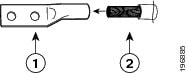
Step 2![]() Insert the stripped end of the grounding wire into the open end of the grounding lug as shown in Figure 6-1.
Insert the stripped end of the grounding wire into the open end of the grounding lug as shown in Figure 6-1.
Figure 6-1 Inserting the Grounding Wire in the Grounding Lug
|
|
|
6 AWG grounding cable with 0.75 in. (19 mm) of insulation stripped from the end |
Step 3![]() Use the crimping tool to crimp the lug to the grounding wire. Verify that the grounding wire is securely attached to the ground lug by attempting to pull the wire out of the crimped lug.
Use the crimping tool to crimp the lug to the grounding wire. Verify that the grounding wire is securely attached to the ground lug by attempting to pull the wire out of the crimped lug.
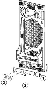
Step 4![]() Remove the adhesive label from one of the power supply grounding pads, and secure the grounding wire lug to the grounding pad threaded studs with two M6 nuts (tighten to a maximum of 40 in-lb [4.5 N·m]). Figure 6-2 shows the location of the grounding pads on the front side of the power supply. Ensure that the grounding lug and the grounding wire do not interfere with other switch hardware or rack equipment.
Remove the adhesive label from one of the power supply grounding pads, and secure the grounding wire lug to the grounding pad threaded studs with two M6 nuts (tighten to a maximum of 40 in-lb [4.5 N·m]). Figure 6-2 shows the location of the grounding pads on the front side of the power supply. Ensure that the grounding lug and the grounding wire do not interfere with other switch hardware or rack equipment.
Figure 6-2 Grounding Pads on the Front of a DC Power Supply
|
|
|
||
|
|
|
Step 5![]() Prepare the other end of the grounding wire and connect it to an appropriate grounding point in your site to ensure an adequate earth ground for the power supply.
Prepare the other end of the grounding wire and connect it to an appropriate grounding point in your site to ensure an adequate earth ground for the power supply.
With the power supply connected to the earth ground, you can connect the power supply to the DC power source (see the “Connecting a DC and HVAC/HVDC Power Supply to DC Power Sources” section).
Connecting a DC Power Supply Directly to DC Power Sources
Warning![]() Before performing any of the following procedures, ensure that power is removed from the DC circuit. Statement 1003
Before performing any of the following procedures, ensure that power is removed from the DC circuit. Statement 1003
Warning![]() Installation of the equipment must comply with local and national electrical codes. Statement 1074
Installation of the equipment must comply with local and national electrical codes. Statement 1074
Warning![]() When installing or replacing the unit, the ground connection must always be made first and disconnected last. Statement 1046
When installing or replacing the unit, the ground connection must always be made first and disconnected last. Statement 1046
To connect a DC power supply to a DC power source, you must connect two isolated inputs from the DC power grid to the power supply for each 3 kW of output power provided by the power supply. For the 3-kW power supply, you connect the four cables (two isolated inputs) to the power supply (use two 3-kW power supplies to output 6 kW of power). For the 6-kW DC power supplies, the cables for two isolated inputs are bundled into one cable with a plug that connects to the power supply (one cable and plug for 3 kW or two cables and plugs for 6 kW).
You can wire these power supplies for combined power mode, power-supply redundancy mode, input-source redundancy mode, and full redundancy mode as follows:
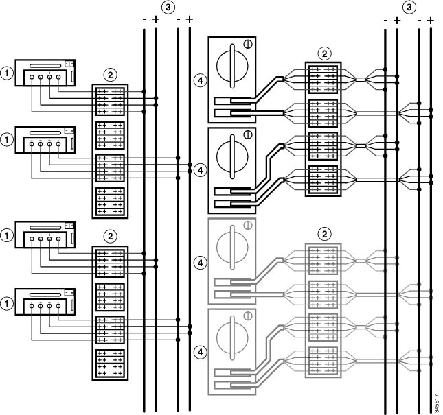
- Combined power mode uses all of the output from all of the connected power supplies. This mode does not provide any power redundancy. You can connect all of the power supplies to the same DC power grid as shown in Figure 6-3.
- Power supply redundancy uses the required number of power supplies plus one (N+1) power supply for redundancy. This mode enables you to replace a power supply during operations. You can connect all of the power supplies to the same DC power grid as shown in Figure 6-4.
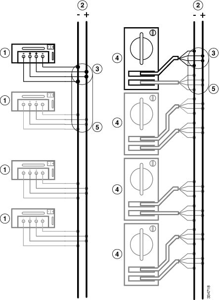
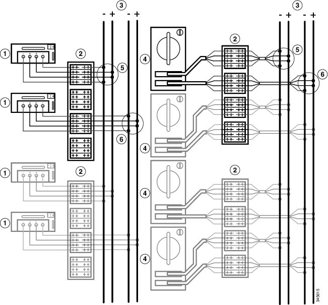
- Input source redundancy uses two power grids. Power supplies with two power cables have each cable connected to a different power grid. Power supplies with one power cable have half of the power supplies connected to one grid and the other half connected to the other grid. To see how these power supplies are connected to two grids, see Figure 6-5.
- Full redundancy provides both the power supply (N+1) redundancy and input source redundancy. You configure an extra power supply and you connect all of the power supplies to two grids, as shown in Figure 6-6.
Note![]() Figure 6-3, Figure 6-4, Figure 6-5, and Figure 6-6 show the required power supplies in black and optional power supplies in gray.
Figure 6-3, Figure 6-4, Figure 6-5, and Figure 6-6 show the required power supplies in black and optional power supplies in gray.
Figure 6-3 Connecting Power Supplies to the Grid for Combined Power Mode
|
|
3-kW DC power supply. You can use a combination of both power supplies. |
|
6-kW DC power supply with one or two power cables plugged in (each cable for 3 kW of power) |
|
|
|
||
|
|
|
Figure 6-4 Connecting DC Power Supplies to the Grid for Power Supply [N+1] Redundancy
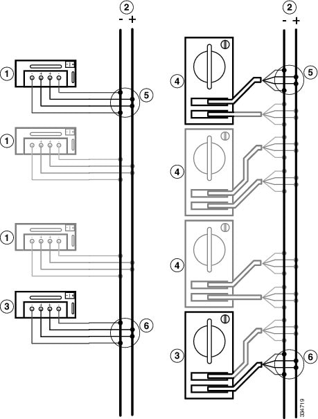
Figure 6-5 Connecting DC Power Supplies to Two Grids for Input Source Redundancy Mode
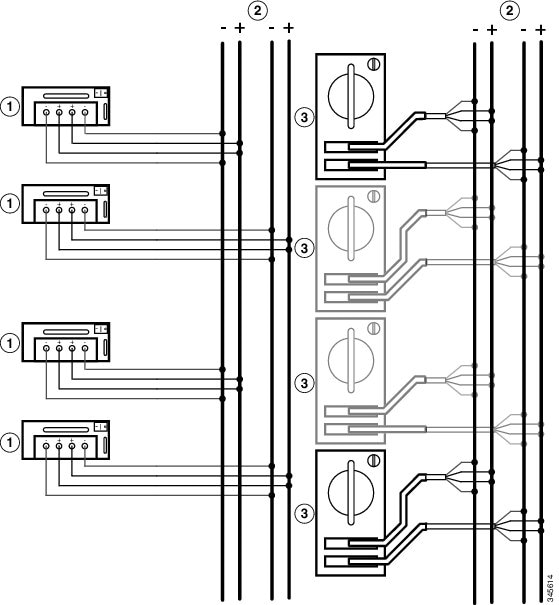
Figure 6-6 Connecting DC Power Supplies to Two Grids for Full Redundancy Mode
If the power supply is too far away for the power cables to reach, you need to install a power interface unit (PIU) in a rack where the power cable can connect it to the power supply (see the “Connecting a Power Supply to DC Power Sources through a Power Interface Unit” section).
Note![]() The power cables required for a 6-kW DC power supply are shipped with the power supply. If you did not receive the correct cables for a 6-kW DC power supply, contact Cisco TAC. You must supply the power cables for a 3-kW DC power supply.
The power cables required for a 6-kW DC power supply are shipped with the power supply. If you did not receive the correct cables for a 6-kW DC power supply, contact Cisco TAC. You must supply the power cables for a 3-kW DC power supply.
Warning![]() Read the installation instructions before connecting the system to the power source. Statement 1004
Read the installation instructions before connecting the system to the power source. Statement 1004
Connecting a 3-kW DC Power Supply Directly to DC Power Sources
If the DC power supply is within one cable length of the DC power sources, you can connect them directly to one another. Otherwise, if you need additional cables, you can connect the cables using a power interface unit (PIU) as explained in the “Connecting a Power Supply to DC Power Sources through a Power Interface Unit” section.
To connect the 3-kW DC power supply directly to one or two DC power sources, follow these steps:
Step 1![]() Turn the power switch to standby (labelled 0 on the power switch).
Turn the power switch to standby (labelled 0 on the power switch).
Step 2![]() Turn off the power at the circuit breakers for the portions of the DC grid power that you are connecting to and verify that all of the LEDs on the power supplies are off.
Turn off the power at the circuit breakers for the portions of the DC grid power that you are connecting to and verify that all of the LEDs on the power supplies are off.
Warning![]() Before performing any of the following procedures, ensure that power is removed from the DC circuit. Statement 1003
Before performing any of the following procedures, ensure that power is removed from the DC circuit. Statement 1003
Step 3![]() Size the power cables to the distance between the power supply and the DC power grid. If you need to cut the cable, cut it at the end that connects to the DC power grid, remove 0.75 inch (19 mm) of insulation from the cut ends, and attach them to the DC power system. Be sure to connect the negative cables to negative lines and positive cables to positive lines.
Size the power cables to the distance between the power supply and the DC power grid. If you need to cut the cable, cut it at the end that connects to the DC power grid, remove 0.75 inch (19 mm) of insulation from the cut ends, and attach them to the DC power system. Be sure to connect the negative cables to negative lines and positive cables to positive lines.
Note![]() For all your power connections, if you are using cables with two different colors, use one color cable for all positive circuits and the other color for all negative circuits.
For all your power connections, if you are using cables with two different colors, use one color cable for all positive circuits and the other color for all negative circuits.
Warning![]() Hazardous voltage or energy may be present on DC power terminals. Always replace cover when terminals are not in service. Be sure uninsulated conductors are not accessible when cover is in place. Statement 1075
Hazardous voltage or energy may be present on DC power terminals. Always replace cover when terminals are not in service. Be sure uninsulated conductors are not accessible when cover is in place. Statement 1075
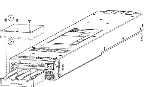
Step 4![]() Remove the three screws that hold down the safety cover for the terminal box on the front of the DC power supply and remove the cover (see Figure 6-7).
Remove the three screws that hold down the safety cover for the terminal box on the front of the DC power supply and remove the cover (see Figure 6-7).
Note![]() The terminal box has four slots for four power terminals (ordered as negative [-], positive [+], positive [+], and negative [-]). Each terminal has two nuts that you use to fasten a power cable to the terminal.
The terminal box has four slots for four power terminals (ordered as negative [-], positive [+], positive [+], and negative [-]). Each terminal has two nuts that you use to fasten a power cable to the terminal.
Figure 6-7 Removing the Safety Cover for the Terminal Box on the 3-kW DC Power Supply
|
|
|
Step 5![]() Install four cables (two positive and two negative cables) in the four terminal slots as follows:
Install four cables (two positive and two negative cables) in the four terminal slots as follows:
a.![]() Unscrew the two nuts in each of the four terminal slots.
Unscrew the two nuts in each of the four terminal slots.
b.![]() Attach and crimp each lug to the end of each power cable.
Attach and crimp each lug to the end of each power cable.
c.![]() Attach each cable lug to the two terminal posts in each slot, fasten with two nuts, and tighten to 40 in-lb (4.5 N·m).
Attach each cable lug to the two terminal posts in each slot, fasten with two nuts, and tighten to 40 in-lb (4.5 N·m).
Note![]() For all your power connections, if you are using cables with two different colors, use one color cable for all positive circuits and the other color for all negative circuits.
For all your power connections, if you are using cables with two different colors, use one color cable for all positive circuits and the other color for all negative circuits.
d.![]() Replace the safety cover on the terminal box and fasten with three screws.
Replace the safety cover on the terminal box and fasten with three screws.
Step 6![]() Install the four cables from the DC power supply to a DC power source as follows:
Install the four cables from the DC power supply to a DC power source as follows:
a.![]() If the unconnected end of each power cable is not stripped of its insulation for the last 0.75 inches (19 mm), use wire strippers to remove that amount of insulation.
If the unconnected end of each power cable is not stripped of its insulation for the last 0.75 inches (19 mm), use wire strippers to remove that amount of insulation.
b.![]() Attach the negative cables to the negative terminals of a DC power source, and attach the positive cables to the positive terminals of the same power source.
Attach the negative cables to the negative terminals of a DC power source, and attach the positive cables to the positive terminals of the same power source.
Note![]() If you are using combined power mode or power supply redundancy mode, connect all the power supplies in the chassis to the same power source. If you are using input source redundancy mode or full redundancy mode, connect half the power supplies to one DC power source and the other half of the power supplies to another DC power source.
If you are using combined power mode or power supply redundancy mode, connect all the power supplies in the chassis to the same power source. If you are using input source redundancy mode or full redundancy mode, connect half the power supplies to one DC power source and the other half of the power supplies to another DC power source.
Step 7![]() For the powered down circuits connected to the power supplies, turn on the power at the circuit breaker. The Input 1 (IN1) and Input 2 (IN2) LEDs turn on each connected power supply.
For the powered down circuits connected to the power supplies, turn on the power at the circuit breaker. The Input 1 (IN1) and Input 2 (IN2) LEDs turn on each connected power supply.
Step 8![]() Turn the power switch on the connected DC power supplies from standby to on (from 0 to 1 as labelled on the power switch for each power supply). The LEDs should flash and then the Output LED should turn on in addition to the Input LEDs.
Turn the power switch on the connected DC power supplies from standby to on (from 0 to 1 as labelled on the power switch for each power supply). The LEDs should flash and then the Output LED should turn on in addition to the Input LEDs.
If the FAULT LED is lit or flashing, call Cisco TAC for assistance.
Connecting a 6-kW DC Power Supply to a DC Power Source
To connect a DC power supply directly to DC power sources, follow these steps:
Step 1![]() Turn the power switch to standby (labelled as STBY).
Turn the power switch to standby (labelled as STBY).
Step 2![]() Turn off the power at the circuit breakers for the portions of the DC grid power that you are connecting to and verify that all of the LEDs on the power supplies are off.
Turn off the power at the circuit breakers for the portions of the DC grid power that you are connecting to and verify that all of the LEDs on the power supplies are off.
Warning![]() Before performing any of the following procedures, ensure that power is removed from the DC circuit. Statement 1003
Before performing any of the following procedures, ensure that power is removed from the DC circuit. Statement 1003
Step 3![]() Size the power cables to the distance between the power supply and the DC power grid. If you need to cut a cable, cut it at the end that connects to the DC power grid, remove 0.75 inches (19 mm) of insulation from the cut ends, and attach it to the DC power source. Be sure to connect the negative cables to negative terminals and positive cables to positive terminals. To determine which color of cables is positive and which color is negative, see the polarity marked on the plug at the other end of the cable.
Size the power cables to the distance between the power supply and the DC power grid. If you need to cut a cable, cut it at the end that connects to the DC power grid, remove 0.75 inches (19 mm) of insulation from the cut ends, and attach it to the DC power source. Be sure to connect the negative cables to negative terminals and positive cables to positive terminals. To determine which color of cables is positive and which color is negative, see the polarity marked on the plug at the other end of the cable.
Note![]() If the supplied 15-foot (4.6-meter) power cables are too short to connect the 6-kW power supply to the DC power source, you must install a PIU within reach of the power supply (see the “Connecting a Power Supply to DC Power Sources through a Power Interface Unit” section).
If the supplied 15-foot (4.6-meter) power cables are too short to connect the 6-kW power supply to the DC power source, you must install a PIU within reach of the power supply (see the “Connecting a Power Supply to DC Power Sources through a Power Interface Unit” section).
Warning![]() Hazardous voltage or energy may be present on DC power terminals. Always replace cover when terminals are not in service. Be sure uninsulated conductors are not accessible when cover is in place. Statement 1075
Hazardous voltage or energy may be present on DC power terminals. Always replace cover when terminals are not in service. Be sure uninsulated conductors are not accessible when cover is in place. Statement 1075
Step 4![]() Connect one or two power cables (Cisco part number N7K-DC-CAB=) to the DC power supply and the DC power grid. Each cable has one plug that connects two fully isolated 1.5 kW input modules to a DC power supply for 3 kW of power. Depending on your power requirements, connect the cables as follows:
Connect one or two power cables (Cisco part number N7K-DC-CAB=) to the DC power supply and the DC power grid. Each cable has one plug that connects two fully isolated 1.5 kW input modules to a DC power supply for 3 kW of power. Depending on your power requirements, connect the cables as follows:
–![]() For 3 kW of output power (combined power mode), use one set of four cables and connect its two fully isolated input modules to the DC power grid (see Figure 6-3).
For 3 kW of output power (combined power mode), use one set of four cables and connect its two fully isolated input modules to the DC power grid (see Figure 6-3).
–![]() For 6 kW of output power (combined power mode) or 3 kW of output power and 3 kW of redundant power (power supply redundant mode), use two sets of four cables and connect their fully isolated input modules to the same DC power grid (see Figure 6-4).
For 6 kW of output power (combined power mode) or 3 kW of output power and 3 kW of redundant power (power supply redundant mode), use two sets of four cables and connect their fully isolated input modules to the same DC power grid (see Figure 6-4).
–![]() For 3 kW of output power and 3 kW of redundant power (input source redundant mode), use two sets of four cables and connect each set of four cables to separate DC power grids (see Figure 6-5).
For 3 kW of output power and 3 kW of redundant power (input source redundant mode), use two sets of four cables and connect each set of four cables to separate DC power grids (see Figure 6-5).
Note![]() For all your power connections, use one color cable for positive circuits and the other color for negative circuits.
For all your power connections, use one color cable for positive circuits and the other color for negative circuits.
Note![]() The cable plugs are keyed to fit one way only in the power supply recepticles. If you cannot insert a plug easily in the receptacle, turn it over and reinsert it. When fully inserted, fasten the plugs to the power supply by tightening their two screws to 8 to 11 in-lb (0.9 to 1.2 N·m).
The cable plugs are keyed to fit one way only in the power supply recepticles. If you cannot insert a plug easily in the receptacle, turn it over and reinsert it. When fully inserted, fasten the plugs to the power supply by tightening their two screws to 8 to 11 in-lb (0.9 to 1.2 N·m).
Step 5![]() For the powered down circuits connected to the power supplies, turn on the power at the circuit breaker. The Input LEDs turn on as follows:
For the powered down circuits connected to the power supplies, turn on the power at the circuit breaker. The Input LEDs turn on as follows:
- For 3 kW of power, either Input 1 and Input 2 LEDs will turn green or the Input 3 and Input 4 LEDs will turn green.
- For 6 kW of power, all four of the Input LEDs will turn green.
Step 6![]() Turn the power switch on the DC power supply from STBY to ON. The LEDs should flash and then the Output LED should turn on in addition to the Input LEDs.
Turn the power switch on the DC power supply from STBY to ON. The LEDs should flash and then the Output LED should turn on in addition to the Input LEDs.
If the FAULT LED is lit or flashing, call Cisco TAC for assistance.
Connecting a 3.5-kW HVAC/HVDC Power Supply to DC Power Sources
To connect a 3.5-kW HVAC/HVDC power supply to a DC power source, follow these steps:
Step 1![]() Ensure that the power supply switch located on the front of the power supply is set at standby (labelled as 0).
Ensure that the power supply switch located on the front of the power supply is set at standby (labelled as 0).
Step 2![]() Plug the DC power cable into the power supply. The built-in latch secures the power cable to the power supply. You can disconnect the power cable from the power supply by pressing the release button on the power cable.
Plug the DC power cable into the power supply. The built-in latch secures the power cable to the power supply. You can disconnect the power cable from the power supply by pressing the release button on the power cable.
Step 3![]() Plug or connect the other end of the power cable into a DC power source supplied by the data center.
Plug or connect the other end of the power cable into a DC power source supplied by the data center.
Note![]() If you are using combined power mode or power supply redundancy mode, connect all the power supplies in the chassis to the same power source. If you are using input source redundancy mode or full redundancy mode, connect half the power supplies to one DC power source and the other half of the power supplies to another DC power source.
If you are using combined power mode or power supply redundancy mode, connect all the power supplies in the chassis to the same power source. If you are using input source redundancy mode or full redundancy mode, connect half the power supplies to one DC power source and the other half of the power supplies to another DC power source.
Warning![]() Take care when connecting units to the supply circuit so that wiring is not overloaded. Statement 1018
Take care when connecting units to the supply circuit so that wiring is not overloaded. Statement 1018
Step 4![]() Turn the power supply switch from standby to on (from 0 to 1 as labeled on the power switch).
Turn the power supply switch from standby to on (from 0 to 1 as labeled on the power switch).
Step 5![]() Verify that the INPUT and OUTPUT power supply LEDs are lit and the FAULT LED is not lit or flashing. For an explanation of all the power supply LEDs and the conditions that they indicate, see Table D-6.
Verify that the INPUT and OUTPUT power supply LEDs are lit and the FAULT LED is not lit or flashing. For an explanation of all the power supply LEDs and the conditions that they indicate, see Table D-6.
Note![]() When you first activate the power supply, you can verify the functionality of the LEDs by checking that each LED turns on for a couple of seconds.
When you first activate the power supply, you can verify the functionality of the LEDs by checking that each LED turns on for a couple of seconds.
If the Fault LED is flashing red, turn the power switch to standby (labeled as 0), check the DC power connections on the power supply and the DC power source, and then turn the power switch back on (labeled as 1). The Input and Output LEDs for the connected power supplies should be green and the Fault LED should be off.
Note![]() Connect the power supply to the appropriate polarity and ground as indicated on the power cable plug or as marked on the ring lug cables.
Connect the power supply to the appropriate polarity and ground as indicated on the power cable plug or as marked on the ring lug cables.
Connecting a Power Supply to DC Power Sources through a Power Interface Unit
If the DC power supplies and the DC power sources are located too far apart for you to connect them with the power cables that you attached to the DC power supplies, you must install a power interface unit (PIU) to connect the power cables to cables that can reach to the DC power sources.
Depending on whether you require the combined power mode, power-supply redundancy, input-source redundancy, or full redundancy, you connect the PIU to one or two power sources as follows:
- For combined power, connect each of the isolated inputs to the same DC power source as shown in Figure 6-8.
- For the power-supply redundancy, connect N+1 power supplies to the same DC power source as shown in Figure 6-9.
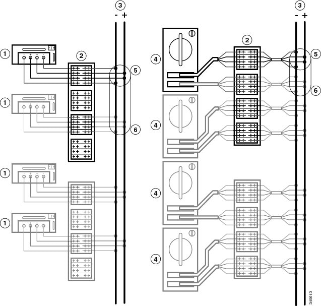
- For the input-source redundancy, connect the power cables as follows to the DC power source (see Figure 6-10):
–![]() For 3-kW power supplies, connect the cables from half of the power supplies to one DC power source and the other half to another DC power source.
For 3-kW power supplies, connect the cables from half of the power supplies to one DC power source and the other half to another DC power source.
–![]() For 6-kW power supplies, connect the cables from one of two plugs on a power supply to one DC power source and the cables from the other plug to another DC power source.
For 6-kW power supplies, connect the cables from one of two plugs on a power supply to one DC power source and the cables from the other plug to another DC power source.
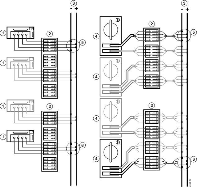
- For the full redundancy, connect the power cables as follows to the DC power source for N+1 power supplies (see Figure 6-11):
–![]() For 3-kW power supplies, connect the cables from half of the power supplies to one DC power source and the other half to another DC power source.
For 3-kW power supplies, connect the cables from half of the power supplies to one DC power source and the other half to another DC power source.
–![]() For 6-kW power supplies, connect the cables from one of two plugs on a power supply to one DC power source and the cables from the other plug to another DC power source.
For 6-kW power supplies, connect the cables from one of two plugs on a power supply to one DC power source and the cables from the other plug to another DC power source.
Figure 6-8 Connecting a PIU to a Power Supply and a 3-, 3.5-or 6-kW Power Supply for Combined Power Mode
|
|
|
||
|
|
|
||
|
|
|
Figure 6-9 Connecting a PIU to a Power Supply and a 3-,3.5- or 6-kW Power Supply for Power Supply Redundancy
|
|
|
||
|
|
|
||
|
|
|
Connections for 3 kW of reserve power (power supply redundancy at least equals the power provided by the power supply providing the maximum amount of available power) |
Figure 6-10 Connecting a PIU to a Power Supply and a 3-, 3.5- or 6-kW Power Supply for Input Source Redundancy
|
|
|
||
|
|
|
||
|
|
|
Connections for 3 kW of reserve power (input source redundancy) |
Figure 6-11 Connecting a PIU to Power Sources and a 3-, 3.5-or 6-kW Power Supply for Full Redundancy
|
|
|
||
|
|
|
Required Tools and Equipment
To install a power interface unit, you need the following tools and materials:
–![]() M6 x 19 mm or four 12-24 x 3/4” Phillips screws (4)
M6 x 19 mm or four 12-24 x 3/4” Phillips screws (4)
–![]() Grounding lug (standard two-holed barrel lug that supports up to 6 AWG wire)
Grounding lug (standard two-holed barrel lug that supports up to 6 AWG wire)
Note![]() Size this wire to meet local and national installation requirements. For U.S. installations, you must provide a 6 AWG copper conductor. For installations outside the U.S., consult your local and national electrical codes. The length of the grounding wire depends on the proximity of the switch to proper grounding facilities. You must supply this wire.
Size this wire to meet local and national installation requirements. For U.S. installations, you must provide a 6 AWG copper conductor. For installations outside the U.S., consult your local and national electrical codes. The length of the grounding wire depends on the proximity of the switch to proper grounding facilities. You must supply this wire.
- Wire-stripping tool
- Number 1 Phillips-head screwdriver with torque capability
- Crimping tool
- Power cables
–![]() Each 3-kW DC power supply requires that you provide four 6-AWG cables for up to 45 A current.
Each 3-kW DC power supply requires that you provide four 6-AWG cables for up to 45 A current.
–![]() Each 6-kW DC power supply comes with a 15-foot (4.6 m) cable with one plug on one end and four wires terminated with lugs.
Each 6-kW DC power supply comes with a 15-foot (4.6 m) cable with one plug on one end and four wires terminated with lugs.
Installing the PIU in a Rack
To install a PIU in a rack, follow these steps:
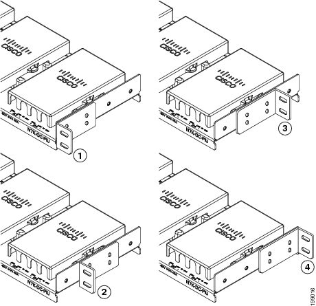
Step 1![]() Position and fasten the two mounting brackets in one of four ways shown in Figure 6-12.
Position and fasten the two mounting brackets in one of four ways shown in Figure 6-12.
Figure 6-12 Positioning the PIU Mounting Brackets
|
|
|
||
|
|
|
Step 2![]() Position the PIU on a rack so that you can connect it to the power supply with the power cables that you are using (user supplied for the 3-kW DC power supply or a 15-foot [4.6 m] cable shipped with the 6-kW DC power supply). Make sure that the PIU is level and its mounting holes align to holes in the mounting rails on the rack.
Position the PIU on a rack so that you can connect it to the power supply with the power cables that you are using (user supplied for the 3-kW DC power supply or a 15-foot [4.6 m] cable shipped with the 6-kW DC power supply). Make sure that the PIU is level and its mounting holes align to holes in the mounting rails on the rack.
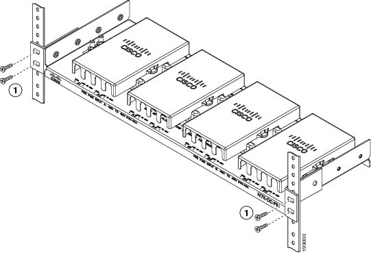
Step 3![]() Fasten the PIU to the rack using four M6 x 19 mm screws or four 12-24 x 3/4 inch screws, as shown in Figure 6-13. Tighten each screw to 40 in-lb (4.5 N·m).
Fasten the PIU to the rack using four M6 x 19 mm screws or four 12-24 x 3/4 inch screws, as shown in Figure 6-13. Tighten each screw to 40 in-lb (4.5 N·m).
Figure 6-13 Fastening the PIU to a Rack
|
|
On each side, fasten two M6 x 19 mm or two 12-24 x 3/4 inch screws (total of four screws for the PIU) and tighten to 40 in-lb (4.5 N·m). |
|
Grounding the PIU
To ground the PIU, follow these steps:
Step 1![]() Unscrew the two M6 nuts that hold the grounding lug to the PIU and remove the grounding lug from the PIU.
Unscrew the two M6 nuts that hold the grounding lug to the PIU and remove the grounding lug from the PIU.
Step 2![]() Use a wire-stripping tool to remove approximately 0.75 inch (19 mm) of the insulation from the end of the 6 AWG grounding wire that you provide.
Use a wire-stripping tool to remove approximately 0.75 inch (19 mm) of the insulation from the end of the 6 AWG grounding wire that you provide.
Step 3![]() Insert the stripped end of the grounding wire into the open end of the grounding lug as shown in Figure 6-1.
Insert the stripped end of the grounding wire into the open end of the grounding lug as shown in Figure 6-1.
Step 4![]() Use the crimping tool to crimp the lug to the 6 AWG grounding wire. Verify that the grounding wire is securely attached to the grounding lug by attempting to pull the wire out of the crimped lug.
Use the crimping tool to crimp the lug to the 6 AWG grounding wire. Verify that the grounding wire is securely attached to the grounding lug by attempting to pull the wire out of the crimped lug.
Step 5![]() Secure the grounding lug to the grounding pad threaded studs with the two M6 nuts and tighten them to 40 in-lb (4.5 N·m). Figure 6-14 shows the location of the grounding pads on the PIU. Ensure that the grounding lug and the grounding wire do not interfere with other PIU equipment.
Secure the grounding lug to the grounding pad threaded studs with the two M6 nuts and tighten them to 40 in-lb (4.5 N·m). Figure 6-14 shows the location of the grounding pads on the PIU. Ensure that the grounding lug and the grounding wire do not interfere with other PIU equipment.
|
|
|
Fasten the lug to the PIU using two M6 nuts and tighten to 40 in-lb (4.5 N·m). |
Step 6![]() Prepare the other end of the grounding wire and connect it to an appropriate grounding point in your site to ensure an adequate earth ground for the PIU.
Prepare the other end of the grounding wire and connect it to an appropriate grounding point in your site to ensure an adequate earth ground for the PIU.
Connecting the DC Power Supply to a Power Source Through a PIU
Before you begin connecting the DC power supply, make sure that the power supply and the PIU are located so that you can connect them with the power cable that you are connecting to the power supply. For the 6-kw power supply, this 15-foot (4.6-m) cable ships with the power supply. For the 3-kw power supply, you supply the 6-AWG power cables.
Warning![]() Read the installation instructions before connecting the system to the power source. Statement 1004
Read the installation instructions before connecting the system to the power source. Statement 1004
To connect the DC power supply to DC power sources through a power interface unit, follow these steps:
Step 1![]() Make sure that the power is turned off for the portion of the DC grid power that you are connecting to.
Make sure that the power is turned off for the portion of the DC grid power that you are connecting to.
Step 2![]() Make sure that the power supply is set to standby (labelled as STBY or 0).
Make sure that the power supply is set to standby (labelled as STBY or 0).
Step 3![]() Size the power cables to the distance between the power supply and the PIU. If you need to cut the cable, cut it at the ends that connect to the PIU, remove 0.75 in. (19 mm) of insulation from the cut end, and reattach the spade connector to the bare ends.
Size the power cables to the distance between the power supply and the PIU. If you need to cut the cable, cut it at the ends that connect to the PIU, remove 0.75 in. (19 mm) of insulation from the cut end, and reattach the spade connector to the bare ends.
Warning![]() Hazardous voltage or energy may be present on DC power terminals. Always replace cover when terminals are not in service. Be sure uninsulated conductors are not accessible when cover is in place. Statement 1075
Hazardous voltage or energy may be present on DC power terminals. Always replace cover when terminals are not in service. Be sure uninsulated conductors are not accessible when cover is in place. Statement 1075
Step 4![]() If you are connecting a 3-kW DC power supply, install four cables (two positive and two negative cables) in the four terminal slots as follows:
If you are connecting a 3-kW DC power supply, install four cables (two positive and two negative cables) in the four terminal slots as follows:
a.![]() Unscrew the three screws on the top of the terminal box and lift off the safety cover (see Figure 6-15).
Unscrew the three screws on the top of the terminal box and lift off the safety cover (see Figure 6-15).
Figure 6-15 Removing the Safety Cover from the Terminal Box
|
|
|
b.![]() Unscrew the two nuts in each of the four terminal slots inside the terminal box.
Unscrew the two nuts in each of the four terminal slots inside the terminal box.
c.![]() Remove a lug from each terminal (total of four lugs).
Remove a lug from each terminal (total of four lugs).
d.![]() For each of the four power cables, carefully crimp a lug on the end of the cable. Be sure not to deform the lug or cable in a way that prevents you from fitting the lug back into one of the terminal slots. Also, ensure that each lug is securely fastened to the cable by attempting to pull the cable out of the lug.
For each of the four power cables, carefully crimp a lug on the end of the cable. Be sure not to deform the lug or cable in a way that prevents you from fitting the lug back into one of the terminal slots. Also, ensure that each lug is securely fastened to the cable by attempting to pull the cable out of the lug.
e.![]() Attach each cable lug to a terminal by placing it on two terminal posts and fasten it with two nuts tightened to 40 in-lb (4.5 N·m).
Attach each cable lug to a terminal by placing it on two terminal posts and fasten it with two nuts tightened to 40 in-lb (4.5 N·m).
Note![]() For all your power connections, if you are using cables with two different colors, use one color cable for all positive circuits and use the other color for all negative circuits.
For all your power connections, if you are using cables with two different colors, use one color cable for all positive circuits and use the other color for all negative circuits.
f.![]() Replace the safety cover on the terminal box and fasten it with three screws.
Replace the safety cover on the terminal box and fasten it with three screws.
Step 5![]() If you are connecting a 6-kW DC power supply, insert the plug end of one or two power cables (Cisco part number N7K-DC-CAB=) to the power receptacles on the power supply and tighten its two screws to 11 to 15 in-lb (1.2 to 1.7 N·m).
If you are connecting a 6-kW DC power supply, insert the plug end of one or two power cables (Cisco part number N7K-DC-CAB=) to the power receptacles on the power supply and tighten its two screws to 11 to 15 in-lb (1.2 to 1.7 N·m).
Note![]() If the plug does not insert easily, turn it over and reinsert it.
If the plug does not insert easily, turn it over and reinsert it.
Step 6![]() Attach each set of four power supply and four power source cables to the PIU as follows:
Attach each set of four power supply and four power source cables to the PIU as follows:
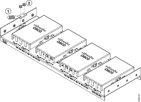
a.![]() Remove the safety cover for a set of four PIU terminals (see Callout 1 in Figure 6-16).
Remove the safety cover for a set of four PIU terminals (see Callout 1 in Figure 6-16).
Figure 6-16 Connecting Power Cables to a PIU
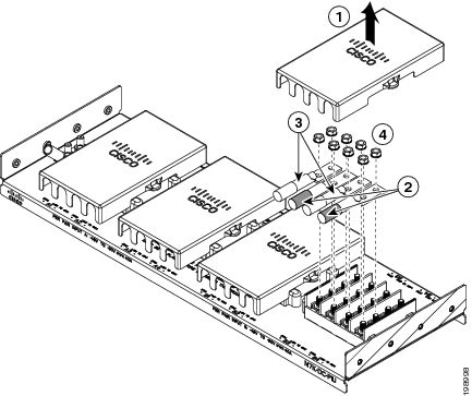
b.![]() In each of the uncovered terminal slots, unscrew and remove two nuts (remove a total of eight nuts) as shown by Callout 4 in Figure 6-16.
In each of the uncovered terminal slots, unscrew and remove two nuts (remove a total of eight nuts) as shown by Callout 4 in Figure 6-16.
c.![]() Attach the lugs for each of the four power supply cables to four terminals and fasten each lug with two nuts. Be sure that each negative cable is attached to a negative terminal and each positive cable is attached to a positive terminal as marked by the PIU slots. See Callouts 2 and 3 in Figure 6-16.
Attach the lugs for each of the four power supply cables to four terminals and fasten each lug with two nuts. Be sure that each negative cable is attached to a negative terminal and each positive cable is attached to a positive terminal as marked by the PIU slots. See Callouts 2 and 3 in Figure 6-16.
Note![]() For all your power connections, if you are using cables with two different colors, use one color cable for all positive circuits and the other color for all negative circuits.
For all your power connections, if you are using cables with two different colors, use one color cable for all positive circuits and the other color for all negative circuits.
d.![]() In each of the uncovered terminal slots, unscrew and remove two nuts (remove a total of eight nuts) as shown by Callout 3 in Figure 6-17.
In each of the uncovered terminal slots, unscrew and remove two nuts (remove a total of eight nuts) as shown by Callout 3 in Figure 6-17.
Figure 6-17 Connecting the Negative Inputs to the PIU
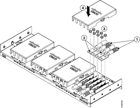
|
|
|
Fasten each of the four lugs with two M6 nuts and tighten to 40 in-lb (4.5 N·m). |
|
|
|
|
e.![]() Attach the lugs for each of the four power source cables to four terminals. Be sure that each negative cable is attached to a negative terminal and each positive cable is attached to a positive terminal. See Callouts 1 and 2 in Figure 6-17.
Attach the lugs for each of the four power source cables to four terminals. Be sure that each negative cable is attached to a negative terminal and each positive cable is attached to a positive terminal. See Callouts 1 and 2 in Figure 6-17.
f.![]() Fasten each lug to its terminal poles with two nuts and tighten to 40 in-lb (4.5 N·m). See Callout 3 in Figure 6-17).
Fasten each lug to its terminal poles with two nuts and tighten to 40 in-lb (4.5 N·m). See Callout 3 in Figure 6-17).
g.![]() Replace the safety cover on the PIU as shown by Callout 4 in Figure 6-17.
Replace the safety cover on the PIU as shown by Callout 4 in Figure 6-17.
Step 7![]() Install the four cables from the PIU to the DC power source as follows:
Install the four cables from the PIU to the DC power source as follows:
a.![]() If the wire is not stripped of its insulation for the last 0.75 inches (19 mm), use wire strippers to remove that amount of insulation from the end of the wire.
If the wire is not stripped of its insulation for the last 0.75 inches (19 mm), use wire strippers to remove that amount of insulation from the end of the wire.
b.![]() Attach the negative cables to the negative terminals of a DC power source, and attach the positive cables to the positive terminals of the DC power source. Depending on whether you need input source redundancy, connect these cables to one or two power sources as follows:
Attach the negative cables to the negative terminals of a DC power source, and attach the positive cables to the positive terminals of the DC power source. Depending on whether you need input source redundancy, connect these cables to one or two power sources as follows:
–![]() For combined power mode or power supply redundancy modes, connect all DC power supply cables to one DC power source.
For combined power mode or power supply redundancy modes, connect all DC power supply cables to one DC power source.
–![]() For input source redundancy mode or full redundancy mode with a 3-kW DC power supply, connect the power cables for half of the power supplies to one DC power source and connect the power cables for the other half of the power supplies to another DC power source.
For input source redundancy mode or full redundancy mode with a 3-kW DC power supply, connect the power cables for half of the power supplies to one DC power source and connect the power cables for the other half of the power supplies to another DC power source.
–![]() For input source redundancy mode or full redundancy mode with a 6-kW DC power supply, connect the four power cables connected to the top power plug on the power supply to one DC power source and connect the four power cables for the bottom power plug on the power supply to another DC power source.
For input source redundancy mode or full redundancy mode with a 6-kW DC power supply, connect the four power cables connected to the top power plug on the power supply to one DC power source and connect the four power cables for the bottom power plug on the power supply to another DC power source.
Step 8![]() For the powered down circuits connected to the power supplies, turn on the power at the circuit breaker. The Input LEDs turn on each connected power supply.
For the powered down circuits connected to the power supplies, turn on the power at the circuit breaker. The Input LEDs turn on each connected power supply.
Step 9![]() Turn the power switch on the connected DC power supplies from standby (labelled as STBY or 0) to on (labelled as ON or 1). The LEDs should flash and then the Output LEDs should turn on in addition to the Input LEDs.
Turn the power switch on the connected DC power supplies from standby (labelled as STBY or 0) to on (labelled as ON or 1). The LEDs should flash and then the Output LEDs should turn on in addition to the Input LEDs.
If the FAULT LED is lit or flashing, call Cisco TAC for assistance.
 Feedback