- Preface
- Overview
- Installing a Cisco Nexus 7004 Switch
- Installing a Cisco Nexus 7009 Chassis
- Installing a Cisco Nexus 7010 Chassis
- Installing a Cisco Nexus 7018 Chassis
- Installing Power Supply Units
- Connecting the Cisco Nexus 7000 Switch to the Network
- Managing system hardware
- Troubleshooting
- Replacement Procedures
- Technical Specifications
- Transceiver and Module Connectors
- Cisco Nexus 7000 Series Accessory Kit Contents
- Chassis and Module LEDs
- Repacking the Nexus 7000 Series Switch for Shipment
- Site Preparation and Maintenance Records
- Preparing for Connections
- Required Tools and Equipment
- Connecting to the Console
- Creating an Initial Switch Configuration
- Setting Up the Management Interface
- Connecting the Supervisor CMP Port
- Connecting an I/O Module
Connecting the Cisco Nexus 7000 Series Switch to the Network
This chapter describes how to connect the Cisco Nexus 7000 Series switch (configure its IP address through a console, set up its management interface, and connect its Ethernet ports to the network) after it has been installed in its rack or cabinet.
Preparing for Connections
When preparing your site for network connections to the Cisco Nexus 7000 Series switch, consider the following for each type of interface:
- Cabling required for each interface type
- Distance limitations for each signal type
- Additional interface equipment needed
Before installing the switch, have all additional external equipment and cables available.
Required Tools and Equipment
- Console cable connector kit—You can find this kit in the accessory kit, which ships with the Cisco Nexus 7000 Series switch.
- Network cabling—You have already routed the network cables to the location of the installed Cisco Nexus 7000 Series switch.
- If you are creating a management connection to the supervisor module, you need to use a modular, RJ-45, UTP straight-through or crossover cable.
Connecting to the Console
Before you create a network management connection for a Cisco Nexus 7000 Series switch or connect the switch to the network, you must create a local management connection through a console terminal and configure an IP address for the switch.
You can also use the console to perform the following functions, each of which can be performed through the management interface after you make that connection later on:
- Configure the switch using the command-line interface (CLI).
- Monitor network statistics and errors.
- Configure Simple Network Management Protocol (SNMP) agent parameters.
- Download software updates.
This local management connection is made between the asynchronous serial port on each Cisco Nexus 7000 Series supervisor module and a console device capable of asynchronous transmission, such as a computer terminal. On the supervisor modules, you use one of the following two asynchronous serial ports:
This port is used for direct connections to the console.
This port is used for modem connections to the console.

Note![]() Before you can connect the console port to a computer terminal, make sure that the computer terminal supports VT100 terminal emulation. The terminal emulation software makes communication between the switch and computer possible during setup and configuration.
Before you can connect the console port to a computer terminal, make sure that the computer terminal supports VT100 terminal emulation. The terminal emulation software makes communication between the switch and computer possible during setup and configuration.
To connect the Cisco Nexus 7000 Series switch to a computer terminal, follow these steps for each supervisor module installed:
Step 1![]() Configure the terminal to match the following default port characteristics:
Configure the terminal to match the following default port characteristics:
Step 2![]() Connect an RJ-45 rollover cable to one of the following serial ports on one of the supervisor modules on the Cisco Nexus 7000 Series switch:
Connect an RJ-45 rollover cable to one of the following serial ports on one of the supervisor modules on the Cisco Nexus 7000 Series switch:
- CONSOLE SERIAL PORT—Use this port if you are not using a modem.
- COM1/AUX SERIAL PORT—Use this port if you are using a modem (available with only Supervisor 1).
You can find this cable in the console cable connector kit, which is part of the accessory kit for the Cisco Nexus 7000 Series switch.
Step 3![]() Route the RJ-45 rollover cable through the center slot in the cable management system and then to the console or modem.
Route the RJ-45 rollover cable through the center slot in the cable management system and then to the console or modem.
Step 4![]() Connect the other end of the RJ-45 rollover cable to the console or to a modem that can connect to the console. If the console or modem cannot use an RJ-45 connection, use one of the following adapters from the console cable connector kit:
Connect the other end of the RJ-45 rollover cable to the console or to a modem that can connect to the console. If the console or modem cannot use an RJ-45 connection, use one of the following adapters from the console cable connector kit:
Creating an Initial Switch Configuration
After you create the local management connection with a console, you must assign an IP address to the switch management interface so that you can then connect the switch to the network.
As soon as you power up the switch, it boots up and asks you a series of questions to configure the switch. This section explains how to configure the IP address that is required to connect the switch to the network. To enable you to connect the switch to the network, you can use the default choices for each configuration except the IP address. You can perform the other configurations at a later time as described in the Cisco Nexus 7000 Series NX-OS Fundamentals Configuration Guide, Release 6.x.
Before you perform the initial switch configuration, you must determine the IP address and netmask needed for the following interfaces:
- Management (Mgmt0) interface
- Connectivity management processor (CMP) for the supervisor module in chassis slot 6 (Supervisor 1 modules only)
- CMP for the supervisor module in chassis slot 5 (Supervisor 1 modules only)
Note![]() You should also know the unique name needed to identify the switch among the devices in the network.
You should also know the unique name needed to identify the switch among the devices in the network.
To define the IP addresses required for an initial switch configuration, follow these steps:
Step 1![]() Power up the switch by turning the power switch from standby (STBY or 0) to on (ON or 1) with each power supply installed in the switch chassis.
Power up the switch by turning the power switch from standby (STBY or 0) to on (ON or 1) with each power supply installed in the switch chassis.
The Input and Output LEDs on each power supply light up (green) when the power supply units are sending power to the switch.
The software asks you to specify a password to use with the switch.
Step 2![]() Enter a new password to use for this switch.
Enter a new password to use for this switch.
The software checks the security strength of your password and rejects your password if it is not considered to be a strong password. To increase the security strength of your password, make sure that it adheres to the following guidelines:
- At least eight characters
- Minimizes or avoids the use of consecutive characters (such as “abcd”)
- Minimizes or avoids repeating characters (such as “aaabbb”)
- Does not contain recognizable words from the dictionary
- Does not contain proper names
- Contains both uppercase and lowercase characters
- Contains numbers as well as letters
Examples of strong passwords include the following:
Note![]() Clear text passwords cannot include the dollar sign ($) special character.
Clear text passwords cannot include the dollar sign ($) special character.

Tip If a password is trivial (such as a short, easy-to-decipher password), the software will reject your password configuration. Be sure to configure a strong password as explained in this step. Passwords are case sensitive.
If you enter a strong password, the software asks you to confirm the password.
Step 3![]() Enter the same password again.
Enter the same password again.
If you enter the same password, the software accepts the password and begins asking a series of configuration questions.
Step 4![]() Until you are asked for an IP address, you can enter the default configuration for each question.
Until you are asked for an IP address, you can enter the default configuration for each question.
Repeat this step for each question until you are asked for the Mgmt0 IPv4 address.
Step 5![]() Enter the IP address for the management interface.
Enter the IP address for the management interface.
The software asks for the Mgmt0 IPv4 netmask.
Step 6![]() Enter a network mask for the management interface.
Enter a network mask for the management interface.
The software asks if you need to edit the configuration.
Step 7![]() Enter no to not edit the configuration.
Enter no to not edit the configuration.
The software asks if you need to save the configuration.
Step 8![]() Enter yes to save the configuration.
Enter yes to save the configuration.
You can now set up the management interface for each supervisor module on the Cisco Nexus 7000 Series switch.
Setting Up the Management Interface
The Cisco Nexus 7000 Series supervisor management port (MGMT ETH) provides out-of-band management, which enables you to use the CLI or the Data Center Network Manager (DCNM) interface to manage the switch by its IP address. This port uses a 10/100/1000 Ethernet connection with an RJ-45 interface.
Note![]() In a dual supervisor switch, you can ensure that the active supervisor module is always connected to the network by connecting the management interface on both supervisor modules to the network. That way, no matter which supervisor module is active, the switch automatically has a management interface that is running and accessible from the network.
In a dual supervisor switch, you can ensure that the active supervisor module is always connected to the network by connecting the management interface on both supervisor modules to the network. That way, no matter which supervisor module is active, the switch automatically has a management interface that is running and accessible from the network.

To connect the supervisor modules to the network, follow these steps for each supervisor module:
Step 1![]() Connect a modular, RJ-45, UTP cable to the MGMT ETH port on the supervisor module.
Connect a modular, RJ-45, UTP cable to the MGMT ETH port on the supervisor module.
Step 2![]() Route the cable through the central slot in the cable management system.
Route the cable through the central slot in the cable management system.
Step 3![]() Connect the other end of the cable to a 10/100/1000 Ethernet port on the network device.
Connect the other end of the cable to a 10/100/1000 Ethernet port on the network device.
Connecting the Supervisor CMP Port
The CMP, which is included on the Cisco Nexus 7000 Series Supervisor 1 module (the CMP is not included on the Supervisor 2 or Supervisor 2E models), is a secondary, lightweight processor that provides a second network interface to the system for use even when the Control Processor (CP) is not reachable. You can access the CMP to perform operations, such as taking over the CP console, restarting the CP, or restarting a particular I/O module.
To connect the CMP to the network, follow these steps for each installed supervisor module:
Step 1![]() Connect a modular, RJ-45, UTP cable to the CMP MGMT ETH port on the supervisor module.
Connect a modular, RJ-45, UTP cable to the CMP MGMT ETH port on the supervisor module.
Step 2![]() Route the cable through the cable management system and to the networking device.
Route the cable through the cable management system and to the networking device.
To configure the port, see the Cisco Nexus 7000 Series Connectivity Management Processor Configuration Guide.
Connecting an I/O Module
After you set up an IP address for the switch and create an out-of-band management connection for the switch, you can connect the copper (1000BASE-T) and fiber-optic (SFP, SFP+, FET, and X2) I/O modules to the network. Table 7-1 lists the connectors and cables that you can use with each type of I/O module.
|
|
|
|
|
|---|---|---|---|
| SFP-H10GB-ACU7M SFP-H10GB-CU1M SFP-10G-AOC1M SFP-10G-ER CWDM-SFP-1xxx |
|||
F2 Series 48-port 1-/10-Gigabit Ethernet XL (N7K-F248XP-25 and N7K-F248XP-25E) |
SFP-H10GB-CU1M SFP-10G-AOC1M SFP-10G-ER CWDM-SFP-xxxx |
||
| SFP-H10GB-ACU7M SFP-H10GB-CU1M SFP-10G-AOC1M SFP-10G-ER SFP-10G-LRM CWDM-SFP-xxxx |
MMF(OM2) |
||
| QSFP-H40G-ACU7M QSFP-H40G-AOC1M QSFP-4X10G-AC7M QSFP-4X10G-AOC1M |
MMF |
||
FET-10G1 |
|||
| SFP-10G-AOC1M SFP-10G-ER SFP-H10GB-CU1M |
|||
CWDM-SFP-1xxx |
|||
CWDM-SFP-1xxx |
|||
| SFP-10G-LR3 SFP-10G-SR-S |
|||
| SFP-H10GB-CU1M SFP-H10GB-ACU7M SFP-10G-AOC1M SFP-10G-ER |
|||
| QSFP-H40G-ACU7M QSFP-H40G-AOC1M QSFP-4X10G-AC7M QSFP-4X10G-AOC1M |
Active Optical Cable Assembly |
||
SFP-10G-SR SFP-10G-BXD-I SFP-H10GB-ACU7M SFP-H10GB-CU1M SFP-10G-AOC1M CWDM-SFP-xxxx |
|||
| QSFP-H40G-AOC1M QSFP-4X10G-AOC1M |
Direct attach breakout copper, active |
|
1.FETs are used only when connecting this I/O module to a Fabric Extender (FEX). 3.Requires the CVR-X2-SFP10G OneX Converter Module (X2 to SFP+ adapter) |
This section includes the following topics:
Connecting or Disconnecting a 1000BASE-T Port
Connecting a 1000BASE-T Port to the Network
You can connect a copper network interface cable with an RJ-45 connector to a port on a 48-port 10/100/1000 Ethernet I/O module (N7K-M148GT-11 and N7K-M148GT-11L).
To connect a 1000BASE-T Ethernet port to the network, follow these steps:
Step 1![]() Attach an ESD-preventative wrist strap and follow its instructions for use.
Attach an ESD-preventative wrist strap and follow its instructions for use.
Step 2![]() Route the interface cable through the cable management slot for the I/O module with the port for this cable.
Route the interface cable through the cable management slot for the I/O module with the port for this cable.
Step 3![]() Insert the RJ-45 connector on the interface cable into the appropriate port on the I/O module.
Insert the RJ-45 connector on the interface cable into the appropriate port on the I/O module.
Disconnecting a 1000BASE-T Port from the Network
You can disconnect a copper network interface cable from a 48-port 10/100/1000 Ethernet module by unplugging its RJ-45 connector from its port on the module.
To disconnect a 1000BASE-T Ethernet port from the network, follow these steps:
Step 1![]() Attach an ESD-preventative wrist strap and follow its instructions for use.
Attach an ESD-preventative wrist strap and follow its instructions for use.
Step 2![]() Unplug the RJ-45 connector on the interface cable from the appropriate port on the Ethernet I/O module.
Unplug the RJ-45 connector on the interface cable from the appropriate port on the Ethernet I/O module.
Step 3![]() (Optional) If you need to remove the cable from the switch, pull it out of the cable management slot.
(Optional) If you need to remove the cable from the switch, pull it out of the cable management slot.
Connecting or Disconnecting an SFP, SFP+, or X2 Port
Depending on the I/O module model that you are using, you can use SFP, SFP+, or X2 transceivers. Some of these transceivers work with fiber-optic cables that you attach to the transceivers and other transceivers work with preattached copper cables. When installing fiber-optic cables for a port, you must install SFP transceivers for 1-Gigabit optical ports or install SFP+ or X2 transceivers or Fabric Extender Transceivers (FETs) for 10-Gigabit optical ports before installing the fiber-optic cable in the transceivers. When removing fiber-optic transceivers, you must remove the fiber-optic cables from a transceiver before removing the transceiver from the port.
Installing a Transceiver
Note Use only the transceivers listed in Table 7-1. Each Cisco transceiver is encoded with model information that enables the switch to verify that the transceiver meets the requirements for the switch.
To install a transceiver, follow these steps:
Step 1![]() Attach an ESD-preventative wrist strap and follow its instructions for use.
Attach an ESD-preventative wrist strap and follow its instructions for use.
Step 2![]() Remove the dust cover from the port cage.
Remove the dust cover from the port cage.
Step 3![]() Remove the dust cover from the port end of the transceiver.
Remove the dust cover from the port end of the transceiver.
Step 4![]() Insert the transceiver into the port.
Insert the transceiver into the port.
Step 5![]() If you are installing fiber-optic cables, connect two optical cables to the installed transceiver (see the “Connecting a Fiber-Optic Cable to a Transceiver” section).
If you are installing fiber-optic cables, connect two optical cables to the installed transceiver (see the “Connecting a Fiber-Optic Cable to a Transceiver” section).
Note![]() If you cannot install the cable into the transceiver, insert or leave the dust plug in the cable end of the transceiver.
If you cannot install the cable into the transceiver, insert or leave the dust plug in the cable end of the transceiver.
Removing a Transceiver
To remove a transceiver, follow these steps:
Step 1![]() Attach an ESD-preventative wrist strap and follow its instructions for use.
Attach an ESD-preventative wrist strap and follow its instructions for use.
Step 2![]() If a cable is installed in the transceiver, remove the cable as explained in the “Disconnecting a Fiber-Optic Cable from a Transceiver” section.
If a cable is installed in the transceiver, remove the cable as explained in the “Disconnecting a Fiber-Optic Cable from a Transceiver” section.
Step 3![]() Remove the transceiver from the port in one of the following ways:
Remove the transceiver from the port in one of the following ways:
- For SFP or SFP+ transceivers, open the clasp on the front of the transceiver and pull the transceiver out of the port.
- For X2 transceivers, pull on the collar on the transceiver to unlock it from the port and pull the transceiver out of the port.
Step 4![]() Insert a dust cover into the port end of the transceiver and place the transceiver on an antistatic mat or into a static shielding bag if you plan to return it to your Cisco representative.
Insert a dust cover into the port end of the transceiver and place the transceiver on an antistatic mat or into a static shielding bag if you plan to return it to your Cisco representative.
Step 5![]() If another transceiver is not being installed, protect the optical port cage by inserting a clean cover.
If another transceiver is not being installed, protect the optical port cage by inserting a clean cover.
Connecting a Fiber-Optic Cable to a Transceiver
To prevent possible damage to the cable or transceiver, install the transceiver in the port before installing the cable in the transceiver.
To install a cable into a transceiver, follow these steps:
Step 1![]() Attach an ESD-preventative wrist strap and follow its instructions for use.
Attach an ESD-preventative wrist strap and follow its instructions for use.
Step 2![]() Remove the dust cover from the port connector on the cable.
Remove the dust cover from the port connector on the cable.
Step 3![]() Remove the dust cover from the cable end of the transceiver.
Remove the dust cover from the cable end of the transceiver.
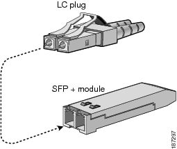
Step 4![]() Align the cable connector with the transceiver and insert the connector into the transceiver until it clicks into place (see Figure 7-1 for SFP or SFP+ transceivers).
Align the cable connector with the transceiver and insert the connector into the transceiver until it clicks into place (see Figure 7-1 for SFP or SFP+ transceivers).
If the cable does not install easily, ensure that it is correctly oriented before continuing.
Figure 7-1 Connecting the LC-Type Cable to an Ethernet SFP or SFP+ Transceiver
Disconnecting a Fiber-Optic Cable from a Transceiver
To remove the cable, follow these steps:
Step 1![]() Attach an ESD-preventative wrist strap and follow its instructions for use.
Attach an ESD-preventative wrist strap and follow its instructions for use.
Step 2![]() Record the cable and port connections for later reference.
Record the cable and port connections for later reference.
Step 3![]() Press the release latch on the cable, grasp the connector near the connection point, and gently pull the connector from the transceiver.
Press the release latch on the cable, grasp the connector near the connection point, and gently pull the connector from the transceiver.
Note![]() If the cable does not remove easily, ensure that any latch present on the cable has been released before continuing.
If the cable does not remove easily, ensure that any latch present on the cable has been released before continuing.
Step 4![]() Insert a dust plug into the cable end of the transceiver.
Insert a dust plug into the cable end of the transceiver.
Step 5![]() Insert a dust plug into the end of the cable.
Insert a dust plug into the end of the cable.
Maintaining Transceivers and Fiber-Optic Cables
Transceivers and fiber-optic cables must be kept clean and dust free to maintain high signal accuracy and prevent damage to the connectors. Attenuation (loss of light) is increased by contamination and should be below 0.35 dB.
Consider the following maintenance guidelines:
- Transceivers are static sensitive. To prevent ESD damage, wear an ESD-preventative wrist strap that is connected to the grounded chassis.
- Do not remove and insert a transceiver more often than is necessary. Repeated removals and insertions can shorten its useful life.
- Keep all optical connections covered when not in use. Clean them before using to prevent dust from scratching the fiber-optic cable ends.
- Do not touch the ends of connectors. Touching the ends can leave fingerprints and cause other contamination.
- Clean the connectors regularly; the required frequency of cleaning depends upon the environment. In addition, clean connectors if they are exposed to dust or accidentally touched. Both wet and dry cleaning techniques can be effective; refer to your site’s fiber-optic connection cleaning procedures.
- Inspect routinely for dust and damage. If you suspect damage, clean and then inspect fiber ends under a microscope to determine if damage has occurred.
 Feedback