-
Cisco MDS 9000 Family Storage Media Encryption Configuration Guide
-
Index
-
New and Changed Information
-
Preface
-
Cisco SME Overview
-
Cisco SME Getting Started
-
Cisco SME Cluster Management
-
Cisco SME Interface Configuration
-
Cisco SME Tape Management
-
Cisco SME Key Management
-
Using the CLI to Configure Cisco SME
-
Cisco SME Best Practices
-
Cisco SME Troubleshooting
-
Cisco SME CLI Commands
-
Offline Data Restore Tool
-
Creating Self-sign certificates
-
Database Backup and Restore
-
Planning for Cisco SME Installation
-
 Feedback
Table Of Contents
Creating a Cisco SME Cluster Using the Cisco SME Wizard
Selecting Master Key Security Levels
Specifying the Key Management Center Server
Confirming the Cluster Creation
Downloading Key File and Storing Keyshares
Basic Security Download Key File
Standard Security Confirmation and Stored Keyshares
Advanced Security Confirmation and Stored Keyshares
Viewing the Transport Settings in Cluster Detail Page
Archiving and Purging a Cisco SME Cluster
Viewing Cisco SME Cluster Details
Viewing Cluster Information Using Fabric Manager Client
Viewing Cluster Information Using Device Manager
Cluster Quorum and Master Switch Election Overview
Three-Switch Cluster Scenarios
In-Service Software Upgrade (ISSU) In a Two-Node Cluster
Cisco SME Cluster Management
The Cisco Fabric Manager provides a web-browser interface that displays real-time views of your network fabrics and lets you configure Cisco Storage Media Encryption with easy-to-use wizards. This chapter contains information about Cisco SME initial configuration and the tasks that are used to manage Cisco SME clusters using Cisco Fabric Manager.
About SME Cluster Management
An SME cluster consists of a group of MDS switches running the SME application in a single fabric environment where each switch is a member or node. The cluster infrastructure enables the SME application to offer high availability and load balancing by providing the ability to communicate and coordinate with the other members to maintain a consistent and distributed view of the application's configuration and operational state.
This chapter contains the following sections:
•
Creating a Cisco SME Cluster Using the Cisco SME Wizard
•
•
•
•
•
•
The process of configuring Cisco SME on an MDS switch with an installed MSM-18/4 module or on a Cisco MDS 9222i switch involves a number of configuration tasks that should be followed in chronological order. See the topics in the Before You Begin online help in Fabric Manager Web Server. Refer to Chapter 2, "Getting Started" and Chapter 4, "Cisco SME Interface Configuration" for information about the tasks that must be completed before creating an Cisco SME cluster.
Creating a Cisco SME Cluster Using the Cisco SME Wizard
The Cisco SME Wizard is an easy-to-use interface that walks you through the process of creating a Cisco SME cluster. The following sections describe the steps in this process:
•
•
•
•
•
Launching Cisco SME Wizard
To launch the Cisco SME wizard, follow these steps:
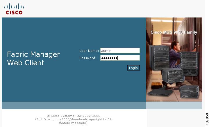
Step 1
For login information, refer to the Cisco MDS 9000 Family Fabric Manager Configuration Guide
Figure 3-1 Cisco Fabric Manager Login
.
Step 2
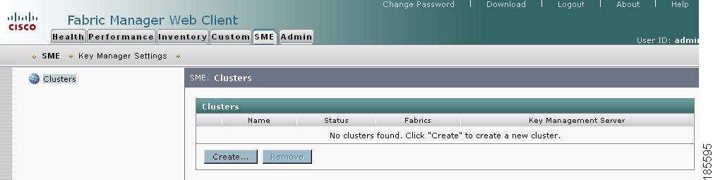
Step 3
Figure 3-2 Fabric Manager Web Client SME Tab
Step 4
The Cisco SME wizard launches to walk you through the easy configuration process.
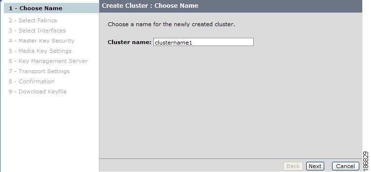
Choosing a Cluster Name
In the Choose Name screen, enter a cluster name. Click Next.
Figure 3-3 Cisco SME Wizard - Create a Cluster Name
Note
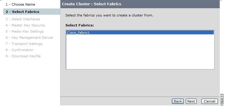
Selecting Fabrics
In the Selecting Fabrics screen, highlight the fabric you want to include in the cluster. Click Next.
Figure 3-4 Cisco SME Wizard - Select Fabrics
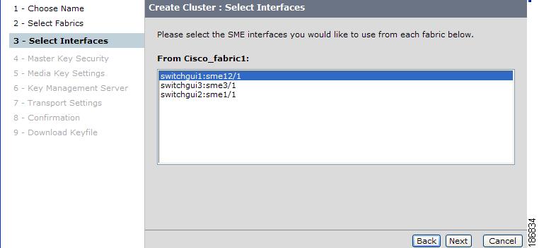
Selecting Interfaces
In the Selecting Interfaces screen, highlight the SME interfaces you want to include in your cluster. Click Next. For information about adding interfaces, see Chapter 4, "Cisco SME Interface Configuration."
Note
Figure 3-5 Select the Cisco SME Interfaces
Selecting Master Key Security Levels
There are 3 master key security levels: Basic, Standard, and Advanced. Standard and Advanced security levels require smart cards. Table 3-1 describes the master key security levels.
Caution
Note
Note
In the Master Key Security screen, select the cluster security type you wish to use. You can choose any of the following security levels:
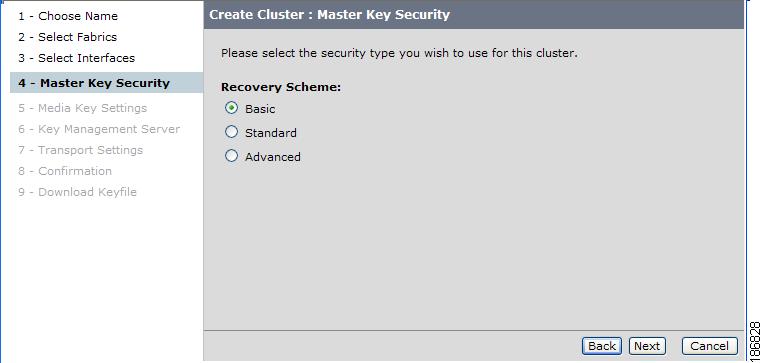
Selecting Basic Security
In the Master Key Security screen, select Basic. Click Next.
Figure 3-6 Selecting Basic Security
For the Basic security level, after the cluster is created the switch generates the master key file and you are prompted for a password to protect the file.
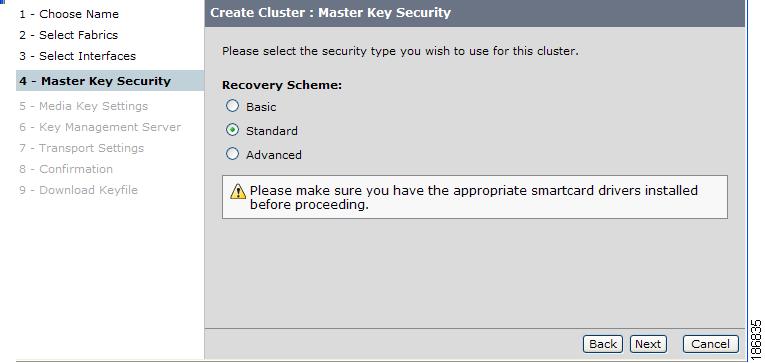
Selecting Standard Security
In the Master Key Security screen, select Standard and click Next. For Standard security, one Cisco SME Recovery Officer must be present to login and enter the smart card PIN.
Figure 3-7 Selecting Standard Security
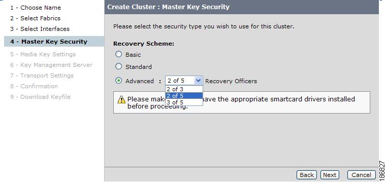
Selecting Advanced Security
When Advanced security is selected, you need to designate the number of cards that are required to recover the master key. This can be 2 or 3 of 5 smart cards or 2 of 3 smart cards. You will need to configure all 5 smart cards during the cluster creations process; however, you will only need the quorum number (that you designated in this step), to recover the master key.
In the Master Key Security screen, select Advanced. Enter the number of required smart cards for the quorum (2 of 3 or 2 of 5 or 3 of 5). Click Next.
•
•
•
Figure 3-8 Selecting Advanced Security
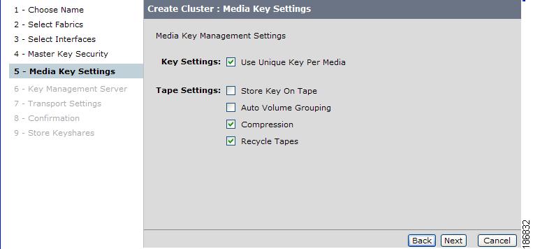
Selecting Media Key Settings
Caution
In the Media Key Settings screen, select the media key settings.
Figure 3-9 Media Key Settings
Table 3-2 lists the media key settings and definitions.
For additional information on media key settings, see Key Management Settings, page 6-4.
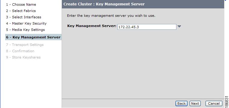
Specifying the Key Management Center Server
In the Key Management Server screen, specify the key management center server from the drop down menu. Click Next.
For information about key management, see Chapter 6, "Cisco SME Key Management."
Note
Figure 3-10 Specify Key Management Server
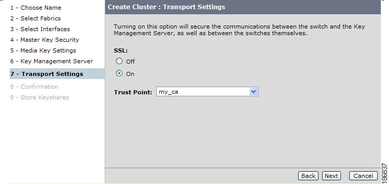
Selecting Transport Settings
In the Transport Settings screen, to enable Transport Settings, select On. If enabled, specify the Trust Point from the dropdown menu.
For more information about Trust Points, see Cisco MDS 9000 Family CLI Configuration Guide.
To enable Transport settings, select On as shown in Figure 3-11.
Figure 3-11 Transport Settings - On
If On is selected in the Transport Setting, SSL is enabled on KMC with the following results:
•
•
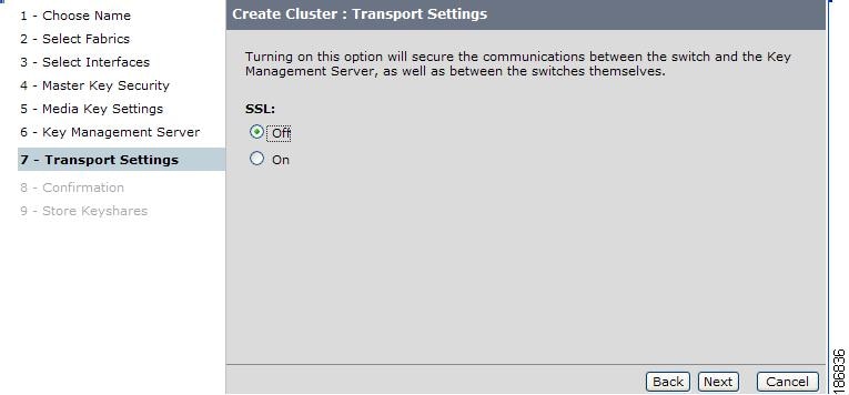
To disable Transport Settings, select Off as shown in Figure 3-12.
Figure 3-12 Transport Settings - Off
For more information on viewing or editing the transport settings in the cluster details page, see Viewing the Transport Settings in Cluster Detail Page
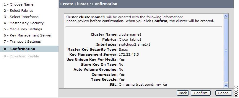
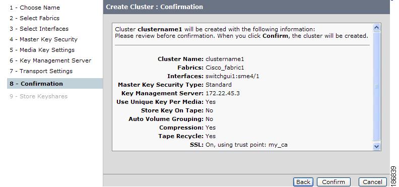
Confirming the Cluster Creation
In the Confirmation screen, review the cluster configuration information. Click Back to change any settings. Click Confirm to create the cluster.
Figure 3-13 Cluster Confirmation
You will see an indication that the operation is in progress until the entire configuration is applied.
Downloading Key File and Storing Keyshares
This section describes the downloading of key file for basic security level and storing keyshares for the standard and advanced security level.
•
•
•
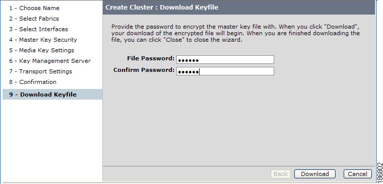
Basic Security Download Key File
For the basic security level, follow these steps:
Step 1
Figure 3-14 Entering the Password for the Master Key File
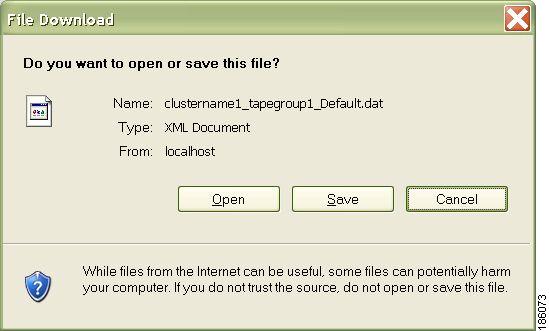
Step 2
Figure 3-15 Saving the Master Key File
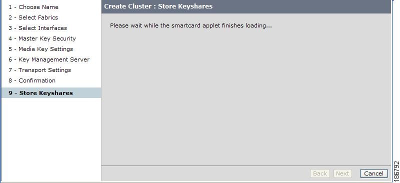
Standard Security Confirmation and Stored Keyshares
For the standard security level, follow these steps:
Step 1
Figure 3-16 Standard Security Confirmation
Step 2
Figure 3-17 Standard Mode - Applet loading
When entering smart card information, note the following:
•
•
•
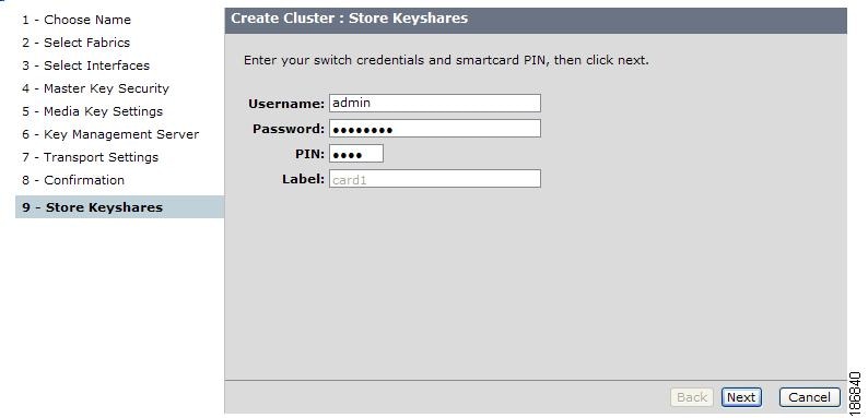
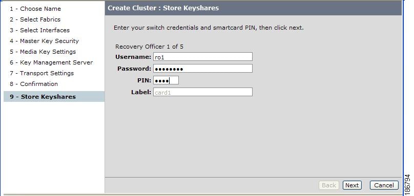
Step 3
Figure 3-18 Entering Switch Credentials and Pin Information
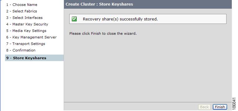
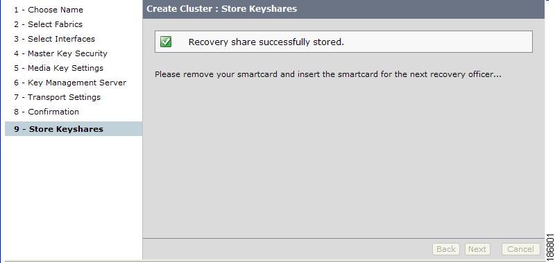
Figure 3-19 Recovery Shares Successfully Stored
Step 4
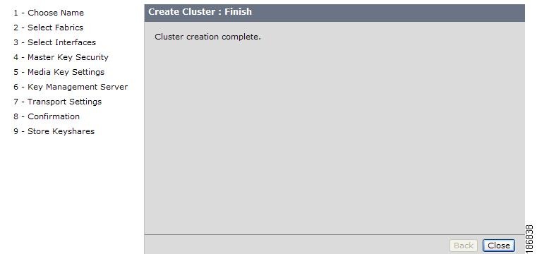
Figure 3-20 Standard Security Cluster Created
Step 5
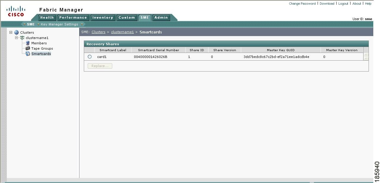
Step 6
Figure 3-21 Viewing Standard Security Smart Card Information
Advanced Security Confirmation and Stored Keyshares
In the advanced security level, follow these steps:
Step 1
Figure 3-22 Advanced Security Confirmation
Step 2
Figure 3-23 Loading the Smart Card Applet
When entering smart card information, note the following:
•
•
•
•
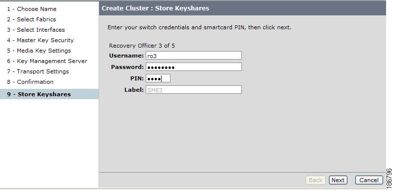
Step 3
Figure 3-24 Entering Switch Credentials and Pin Information For the First Recovery Officer
You will see a notification that the keyshare is being stored. This notification will be shown after each keyshare is stored.
Step 4
Figure 3-25 Storing the Keyshare For the First Recovery Officer
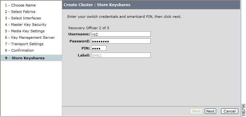
Step 5
Figure 3-26 Entering Switch Credentials and Pin Information For the Second Recovery Officer
Step 6
Figure 3-27 Entering Switch Credentials and Pin Information For the Third Recovery Officer
Step 7
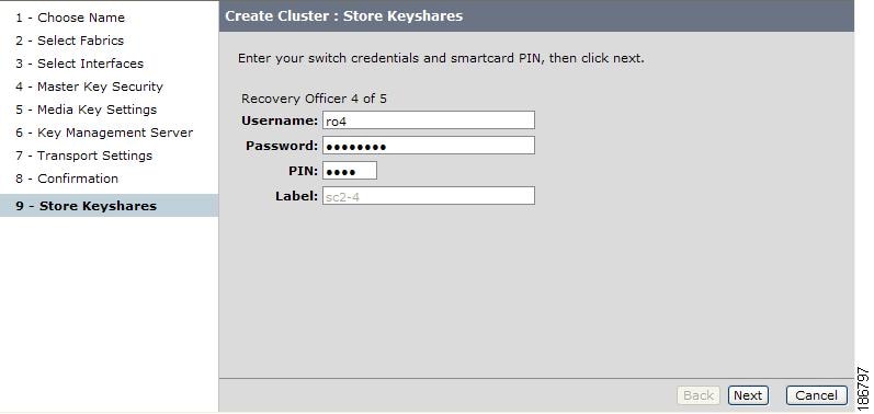
Figure 3-28 Entering Switch Credentials and Pin Information For the Fourth Recovery Officer
Step 8
Figure 3-29 Entering Switch Credentials and Pin Information For the Fifth Recovery Officer
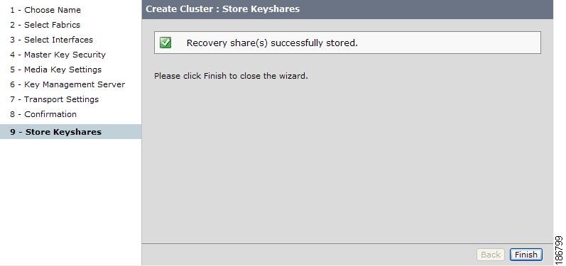
Step 9
Figure 3-30 Recovery Shares Successfully Stored
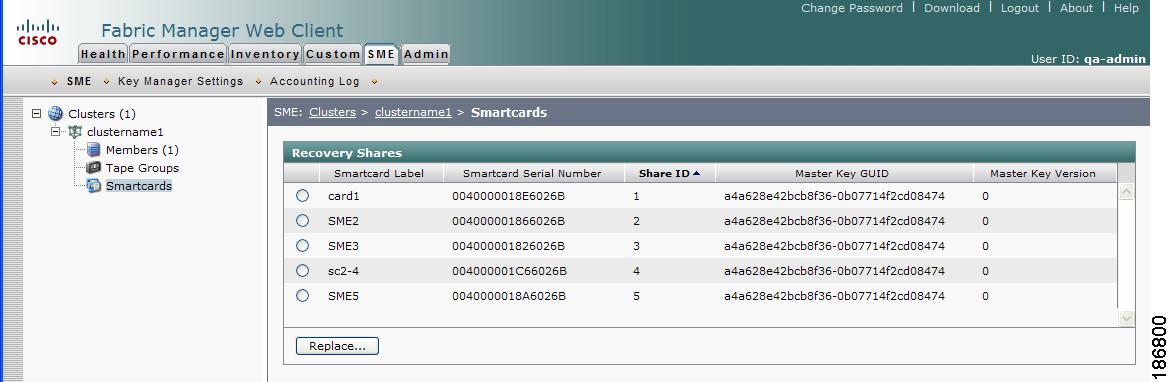
Step 10
Figure 3-31 Viewing Advanced Security Smart Card Information
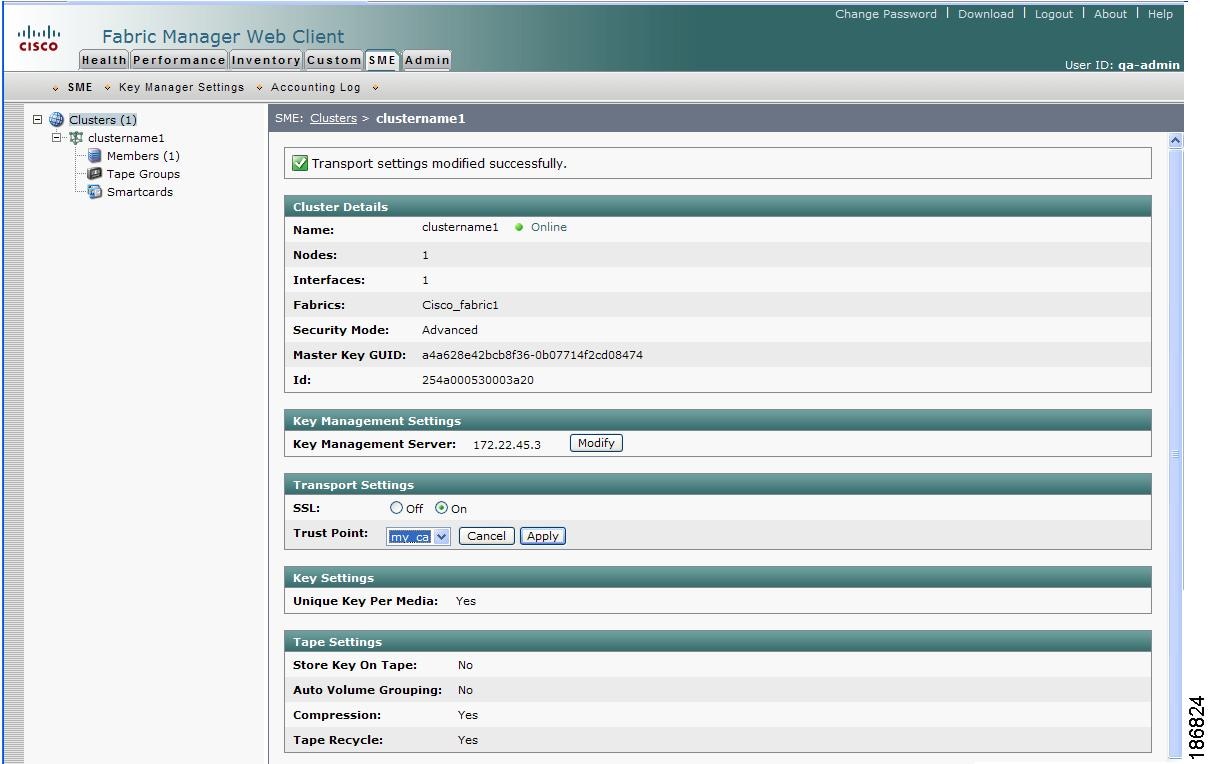
Viewing the Transport Settings in Cluster Detail Page
To view the transport settings, select the newly created cluster in the navigation pane to display the cluster detail page.
Figure 3-32 Transport Settings - SSL On
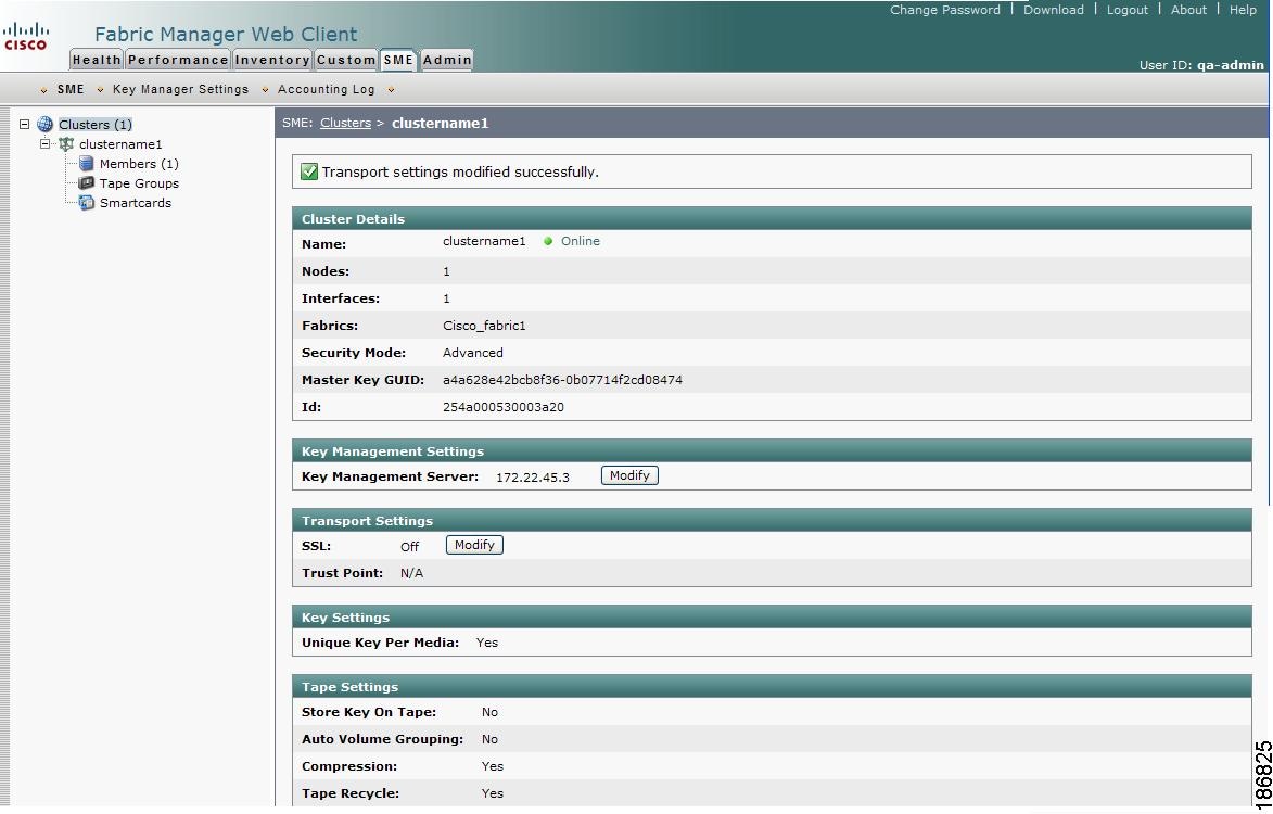
Figure 3-33 Transport Settings - SSL Off
Figure 3-34 Transport Settings - SSL Modify
You can also modify the transport settings in the cluster detail page. Select SSL and choose a Trust Point from the drop down menu. Click Apply to save the settings.
Archiving and Purging a Cisco SME Cluster
You can archive clusters that are Online, Pending, or Deprecated. For information on cluster states, see Viewing Cluster States.
Archiving and then purging a Cisco SME cluster involves the following:
•
•
•
•
Note
Archiving a Cisco SME Cluster
Archiving deletes the cluster from the switch and it retains the keys in the Cisco KMC.
To change the cluster state to Archived, follow these steps:
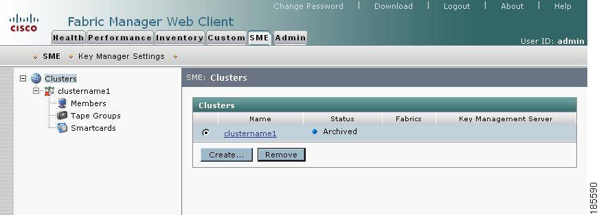
Step 1
Step 2
Note
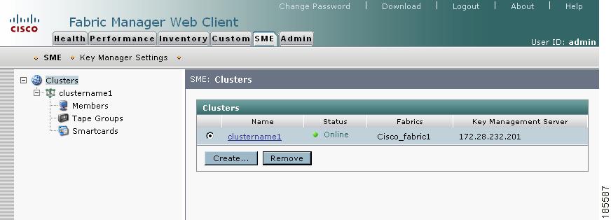
Figure 3-35 Cisco SME Clusters
Caution
Step 3
Figure 3-36 Cluster Removal Confirmation
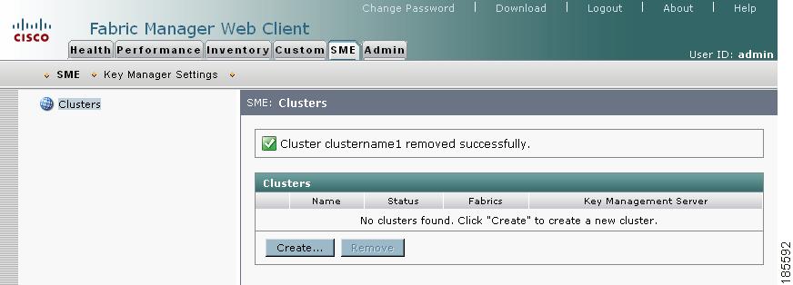
Step 4
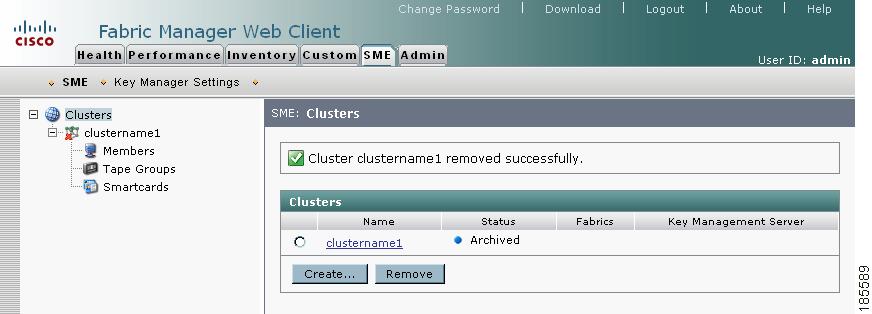
Figure 3-37 Cluster Archived
Purging a Cisco SME Cluster
Purging a Cisco SME cluster includes the following:
•
•
•
•
Note
To purge a Cisco SME cluster, follow these steps:
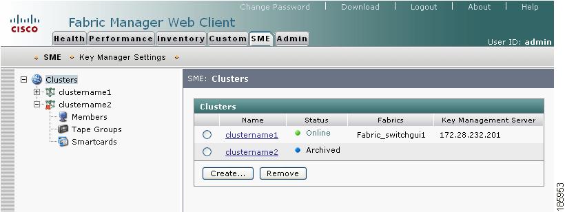
Step 1
Step 2
Figure 3-38 Archived Cisco SME Cluster
Step 3
Caution
Figure 3-39 Purging Confirmation
Figure 3-40 Purged Cluster Confirmation
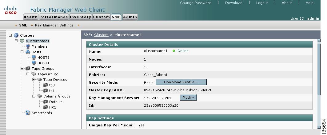
Viewing Cisco SME Cluster Details
To view cluster details, click the cluster name.
Figure 3-41 Viewing Cluster Details
Note
Viewing Cluster States
Cisco SME clusters can be in one of the following cluster states:
•
•
•
•
•
To view the cluster status, follow these steps:
Step 1
Step 2
Figure 3-42 Viewing Cluster States
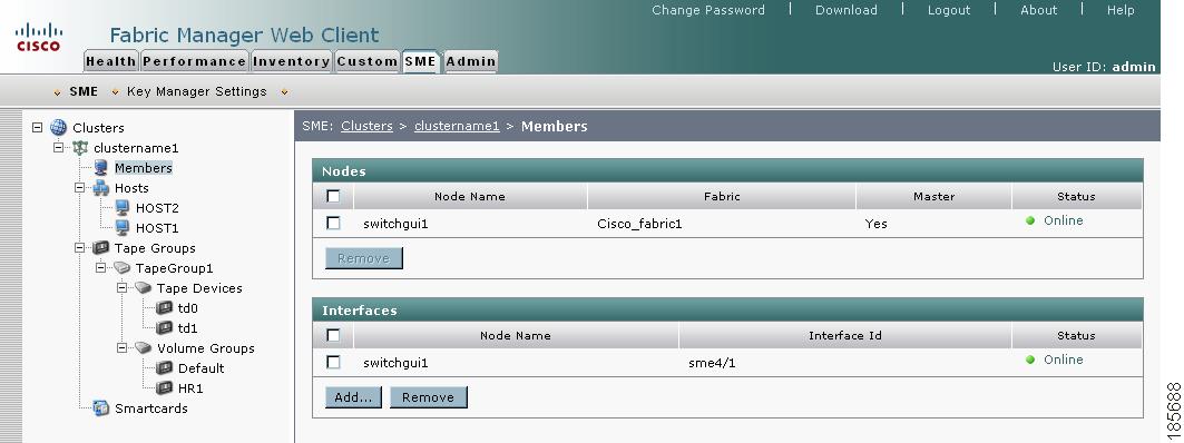
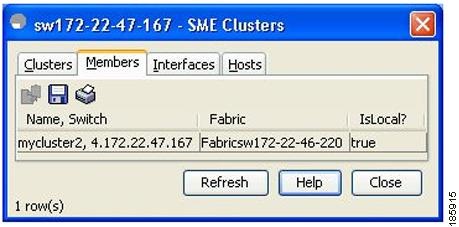
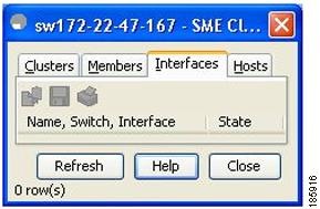
Viewing Members in a Cluster
When you view members of a cluster, you see the switches and the interfaces that have been added to a cluster.
To view the Cisco SME interfaces and switches in a cluster, follow these steps:
Step 1
Figure 3-43 Viewing Members (Switches and Interfaces) in a Cluster
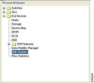
Viewing Cluster Information Using Fabric Manager Client
To view Cisco SME cluster information using Fabric Manager Client, follow these steps:
Step 1
Figure 3-44 Physical Attributes Pane
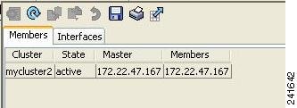
Step 2
Figure 3-45 Cluster Member Information in Fabric Manager
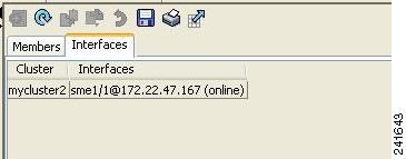
Step 3
Figure 3-46 Cluster Interface Information in Fabric Manager
Viewing Cluster Information Using Device Manager
To view Cisco SME cluster information using Device Manager, follow these steps:
Step 1
Step 2
Step 3
Step 4
Step 5
Figure 3-47 Viewing Cisco SME Cluster Information in Device View
Figure 3-48 Viewing Cisco SME Member Information in Device View
Figure 3-49 Viewing Cisco SME Interface Information in Device View
Cluster Quorum and Master Switch Election Overview
This section describes the Cisco SME cluster quorum and the process for electing the master switch in a cluster. The section includes the following:
In this section, the term switch is used to describe a Cisco MDS 9000 Family switch that is part of a Cisco SME cluster. In addition, the following terms are used in this section.
Node ID
Every switch in a cluster has a node ID. Cisco SME assigns a node ID to every new switch as it is added to the cluster. The switch where the cluster is created is assigned the node ID of 1. This is the master switch. When a new switch is added to the cluster, it is assigned the next available higher node ID. For example, when a second switch is added to the cluster it gets the node ID of 2 and the third switch gets the node ID of 3, and so on.
Cluster View
The cluster view is the set of switches that are part of the operational cluster.
Cluster Quorum
For a cluster to be operational, it must include more than half the number of configured switches in the cluster view. Thus, in an N-node cluster, N/2 + 1 nodes form a cluster quorum.
If N is even, the cluster quorum requires N/2 nodes and additionally, the presence of the switch with the lowest node ID.
The quorum logic ensures that in the event of cluster partitions, at most one partition can be operational. All other switches are nonoperational. This guarantees the consistency of the cluster.
Master Switch Election
When a cluster is created, the switch on which the cluster is created becomes the cluster master switch. When the master switch fails or is rebooted, another switch takes over as the master switch. The master election logic uses the node ID and the latest cluster configuration to determine which switch in the cluster will become the master switch. The master election logic is describe as follows:
•
–
•
–
For example, there are 3 switches S1, S2 and S3 with node IDs 1, 2 and 3 respectively. If switches S2 and S3 form a quorum then switch S2 becomes the master switch. Even if switch S1 with the node ID of 1 comes up and joins the cluster at a later time, switch S2 continues to be the master. However, if switch S2 goes down for any reason, switch S1 will become the master switch.
Two-Switch Cluster Scenarios
According to the cluster quorum logic (see Cluster Quorum), a cluster with 2 configured switches can be operational if both switches are operational or the switch with the lowest node ID is operational.
In the latter case, the switch with the lowest node ID is the master of the 1-switch cluster. The other switch could have failed or simply lost connectivity to the operational switch. In either case, the switch with the higher node ID would become nonoperational. If the node with the lower node ID failed, the other switch cannot form an operational cluster.
The examples that follow describe these scenarios. The first three examples consider single switch failures.
1.
When the switches lose connectivity between them, the master switch S1 continues to be operational since it has the lower node ID and can form an (N/2) switch cluster. Switch S2 becomes non-operational.
2.
When the switches lose connectivity between them, switch S2 becomes non-operational and S1 takes over as the master to form a 1-switch cluster. This is consistent with the quorum logic in a 2-switch cluster (N/2 with lowest node ID).
3.
When S1 comes up, S1 and S2 will form a 2-switch cluster.
The next set of examples consider reboots of both switches (S1 with node ID 1 and S2 with node ID 2).
Caution
4.
a.
b.
5.
6.
When S2 comes up and if it happens to have the latest cluster configuration in the startup configuration (this can happen if you did not save the running configuration to the startup configuration on S1 but did so on S2), it will not be able to join the cluster formed by S1. You may be required to follow the recovery procedures described in Chapter 9, "Cisco SME Troubleshooting" to bring S2 back into the cluster.
Caution
Three-Switch Cluster Scenarios
In a 3-switch cluster, the quorum requires 2 switches to be in the cluster view (N/2 + 1). The examples below explain three scenarios in a 3-switch cluster with switches S1 (node ID 1), S2 (node ID 2) and S3 (node ID 3). S1 is the master switch.
1.
2.
3.
The examples below consider reboots on all switches in the cluster.
Caution
4.
a.
b.
5.
If the third switch happens to be running the latest cluster configuration in the startup configuration (this can happen if you save the running configuration only on this switch but not on the other two), the third switch will not be able to join the cluster. You may be required to follow the recovery procedures described in Chapter 9, "Cisco SME Troubleshooting" to bring this switch back into the cluster.
Caution
Four-Switch Cluster Scenarios
The four-switch cluster scenario is very similar to the examples above. The cluster will be operational if the cluster view has at least 3 switches (N/2 + 1), or if the cluster view has 2 switches including the switch with the lowest node ID (N/2 with lowest node ID).
In-Service Software Upgrade (ISSU) In a Two-Node Cluster
In-Service Software Upgrade (ISSU) is a comprehensive, transparent software upgrade application that allows you to deploy bug fixes and add new features and services without any disruption to the traffic.
In a cluster comprising of the MDS 9222i switches as nodes, if the nodes are not able to communicate, then the node having the lowest node identifier (node ID) remains in the cluster while the other node leaves the cluster. However, when an ISSU is performed on a node having the lowest node identifier, a complete loss of the cluster results because both the nodes leave the cluster.
This undesirable situation is addressed in a two-node cluster as follows:
•
•
•
Note