Feedback
Table Of Contents
Ports to Include in a Server-Based Job
Understanding DMM Topologies
Cisco MDS DMM is designed to support a variety of SAN topologies. The SAN topology influences the location of the SSM module and the DMM feature configuration. The following sections describe common SAN topologies and their implications for DMM:
•
Ports to Include in a Server-Based Job
Overview
Cisco DMM supports homogeneous SANs (all Cisco MDS switches), as well as heterogeneous SANs (a mixture of MDS switches and other vendor switches). In a heterogeneous SAN, you must connect the existing and new storage to Cisco MDS switches.
In both homogeneous and heterogeneous SANs, Cisco MDS DMM supports dual-fabric and single-fabric SAN topologies. Dual-fabric and single-fabric topologies both support single path and multipath configurations.
In a single path configuration, a migration job includes only the one path (which is represented as an initiator/target port pair). In a multipath configuration, a migration job must include all paths (which are represented as two initiator/target port pairs).
FC-Redirect
When a data migration job is in progress, all traffic (in both directions) sent between the server HBA port and the existing storage is intercepted and forwarded to the SSM, using the FC-Redirect capability.
FC-Redirect requirements for the SAN topology/configuration include the following:
•
•
•
•
•
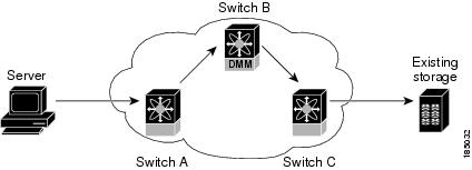
The following examples show the server-to-storage packet flow when a data migration job is in progress. For clarity, the example shows the SSM and the existing storage connected to separate switches. Our recommended practice is to connect the existing storage to the same switch as the SSM.
In Figure 6-1, the server HBA port is connected to switch A and the existing storage is connected to switch C. Both switches have FC Redirect capability. The SSM is installed on switch B. All three switches are running SAN OS 3.2(1) or later.
Figure 6-1 Host Connected to FC-Redirect Switch
When the data migration job is started, FC-Redirect is configured on switch A to divert the server traffic to the SSM. FC-Redirect is configured on switch C to redirect the storage traffic to the SSM.
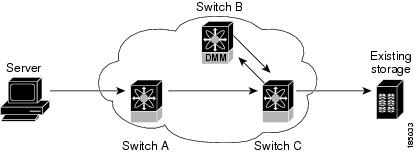
In Figure 6-2, the server HBA port is connected to switch A, which does not have FC-Redirect capability or is not running SAN OS 3.2(1) or later. The existing storage is connected to switch C, which has FC-Redirect capability. The SSM is installed on switch B. Switches B and C are running SAN OS 3.2(1) or later.
When the data migration job is started, FC-Redirect is configured on switch C to redirect the server and storage traffic to the SSM. This configuration introduces additional network latency and consumes additional bandwidth, because traffic from the server travels an extra network hop (A to C, C to B, B to C). The recommended configuration (placing the SSM in switch C) avoids the increase in network latency and bandwidth.
Figure 6-2 Host not Connected to FC-Redirect Switch
DMM Topology Guidelines
When determining the provisioning and configuration requirements for DMM, note the following guidelines related to SAN topology:
•
•
•
•
•
•
Note
Homogeneous SANs
A homogeneous SAN contains only Cisco MDS switches. Most topologies fit the following categories:
•
•
•
For all of the above categories, we recommend that you locate the SSM in the switch closest to the storage devices. Following this recommendation ensures that DMM introduces no additional network traffic during data migrations.
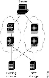
Figure 6-3 shows a common SAN topology, with servers at the edge of the network and storage arrays in the core.
Figure 6-3 Homogeneous SAN Topology
In a homogeneous network, you can locate the SSM on any DMM-enabled MDS switch in the fabric. We recommend that you install the SSM in the switch connected to the existing storage. You should also connect the new storage to the same switch as the existing storage. If the SSM is on a different switch from the storage, additional ISL traffic crosses the network during the migration (all traffic between storage and server is routed through the SSM).
Heterogeneous SANs
When planning Cisco MDS DMM data migration for a heterogeneous SAN, note the following guidelines:
•
•
Depending on the topology, you may need to make configuration changes prior to data migration.
Ports to Include in a Server-Based Job
This section provides guidelines for configuring server-based migration jobs.
When creating a server-based migration job, you must include all possible paths from the host to the LUNs being migrated. This is because all writes to a migrated LUN need to be mirrored in the new storage until the job is destroyed, so that no data writes are lost.
Therefore, all active ports on the existing storage that expose the same set of LUNs to the server must be added to a single data migration job.
In a multipath configuration, two or more active storage ports expose the same set of LUNs to two HBA ports on the server (one initiator/target port pair for each path). Multipath configurations are supported in dual-fabric topologies (one path through each fabric) and in single-fabric topologies (both paths through the single fabric).
In a single path configuration, only one active storage port exposes the LUN set to the server. The migration job includes one initiator/target port pair (DMM does not support multiple servers accessing the same LUN set).
The following sections describe how to apply the rules to various configurations:
•
•
•
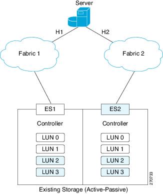
Single LUN Set, Active-Active Array
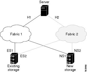
In the example shown in Figure 6-4, the server accesses three LUNs over Fabric 1 using storage port ES1. The server accesses the same LUNs over Fabric 2 using storage port ES2.
Both storage ports (ES1 and ES2) must be included in the same data migration job, as both ports are active and expose the same LUN set.
Figure 6-4 Single LUN Set, Active-Active Array
You create a data migration job with the following configuration:
Note
Multiple LUN Set, Active-Active Arrays
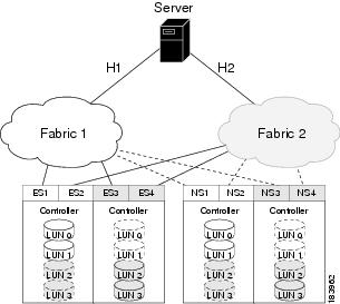
In the example shown in Figure 6-5, the server accesses three LUNs over Fabric 1 using storage port ES1. The server accesses the same LUNs over Fabric 2 using storage port ES2. The server accesses three different LUNs over Fabric 1 using storage port ES3, and accesses the same LUNs over Fabric 2 using storage port ES4.
Figure 6-5 Multiple LUN set, active-active arrays
You need to create two data migration jobs, because the server has access to two LUN sets on two different storage ports. You need to include two storage ports in each data migration job, as they are active-active multipathing ports.
One migration job has the following configuration:
This job includes three data migration sessions (for LUNs 1,2, and 3).
The other migration job has the following configuration:
This job includes three data migration sessions (for LUNs 7,8, and 9).
Single LUN Set, Active-Passive Array
In an active-passive array, the LUNs exposed by a storage port may be active or passive.
Case 1: Each controller has two active ports
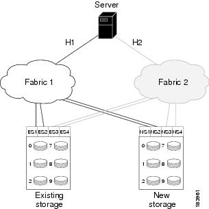
In the example shown in Figure 6-6, the server accesses a single LUN set. However, all LUNs are not active on a single storage port. The active-passive array in the example has two controllers, each with two ports. LUN 0 and LUN 1 are active on ES1 and ES2. LUN 2 and LUN 3 are active on ES3 and ES4.
Logically, the server sees two active LUN sets, accessed from two different storage ports each paired for multipathing.
Figure 6-6 Case 1: Single LUN Set, Active-Passive Array
The server accesses LUN 0 and LUN 1 over Fabric 1 using storage port ES1. The server accesses the same LUNs over Fabric 2 using storage port ES2. The server accesses LUN 2 and LUN 3 over Fabric 1 using storage port ES3, and accesses the same LUNs over Fabric 2 using storage port ES4.
You need to create two data migration jobs, because the server has access to two LUN sets over two different storage ports. Each of the data migration jobs includes two storage ports, because both ports access the active LUNs on the storage.
Only the active LUNs are included in each job. (LUNs 0 and 1 in one job and LUNs 1 and 2 in the other job).
Note
One migration job has the following configuration:
This job includes two data migration sessions (for LUNs 0 and 1).
The other migration job has the following configuration:
This job includes two data migration sessions (for LUNs 2 and 3).
Case 2: Each controller has only one active port
In the example shown in Figure 6-7, the server accesses a single LUN set. However, all LUNs are not active on a single storage port. The active-passive array in the example has two controllers, each with a single port. LUN 0 and LUN 1 are active on ES1. LUN 2 and LUN 3 are active on ES2.
Logically, the server sees two active LUN sets, accessed from different storage ports.
Figure 6-7 Case 2: Single LUN Set, Active-Passive Array
The server accesses LUN 0 and LUN 1 over Fabric 1 using storage port ES1. The server accesses LUN 3 and LUN 4 over Fabric 2 using storage port ES2.
You need to create two data migration jobs, because the server has access to two LUN sets over two different storage ports. Each of the data migration jobs includes the ports from a single fabric.
One migration job has the following configuration:
The other migration job has the following configuration: