Intranet and Extranet VPN Business Scenarios
Available Languages
Table Of Contents
Site-to-Site and Extranet VPN Business Scenarios
Configuring the Tunnel Interface, Source, and Destination
Verifying the Tunnel Interface, Source, and Destination
Step 2—Configuring Network Address Translation
Configuring Static Inside Source Address Translation
Verifying Static Inside Source Address Translation
Step 3—Configuring Encryption and IPSec
Additional Configuration Required for IKE Policies
Configuring the Gateway for Digital Certificate Interoperability
Configuring a Different Shared Key
Configuring IPSec and IPSec Tunnel Mode
Defining Transform Sets and Configuring IPSec Tunnel Mode
Verifying Transform Sets and IPSec Tunnel Mode
Applying Crypto Maps to Interfaces
Verifying Crypto Map Interface Associations
Step 4—Configuring Quality of Service
Configuring Network-Based Application Recognition
Verifying a Class Map Configuration
Attaching a Policy Map to an Interface
Verifying a Policy Map Configuration
Configuring Weighted Fair Queuing
Verifying Weighted Fair Queuing
Configuring Class-Based Weighted Fair Queuing
Configuring Class Policy in the Policy Map (Tail Drop)
Attaching the Service Policy and Enabling CBWFQ
Verifying Class-Based Weighted Fair Queuing
Step 5—Configuring Cisco IOS Firewall Features
Creating Extended Access Lists Using Access List Numbers
Verifying Extended Access Lists
Applying Access Lists to Interfaces
Verifying Extended Access Lists Are Applied Correctly
Comprehensive Configuration Examples
Headquarters Router Configuration
Remote Office Router Configuration
Headquarters Router Configuration
Business Partner Router Configuration
Site-to-Site and Extranet VPN Business Scenarios
This chapter explains the basic tasks for configuring IP-based, site-to-site and extranet Virtual Private Networks (VPNs) on a Cisco IOS VPN gateway using generic routing encapsulation (GRE) and IPSec tunneling protocols. Basic security, Network Address Translation (NAT), Encryption, Cisco IOS weighted fair queuing (WFQ), and extended access lists for basic traffic filtering are configured.

Note
This chapter describes basic features and configurations used in a site-to-site VPN scenario. Some Cisco IOS security software features not described in this document can be used to increase performance and scalability of your VPN. For up-to-date Cisco IOS security software features documentation, refer to the Cisco IOS Security Configuration Guide and the Cisco IOS Security Command Reference publication. To access the publication, log on to Cisco.com, and select the following links under "Service & Support": Technical Documents: Cisco IOS Software: Cisco IOS Release 12.2: Configuration Guides and Command References.
This chapter includes the following sections:
•
•
•
•
•
•
Note
Scenario Descriptions
This section includes the following topics:
•
•
•
•
•
•
•
•
•
•
•
•
Site-to-Site Scenario
Figure 3-1 shows a headquarters network providing a remote office access to the corporate intranet. In this scenario, the headquarters and remote office are connected through a secure GRE tunnel that is established over an IP infrastructure (the Internet). Employees in the remote office are able to access internal, private web pages and perform various IP-based network tasks.
Note
Figure 3-1 Site-to-Site VPN Business Scenario
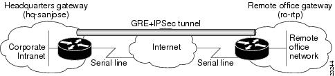
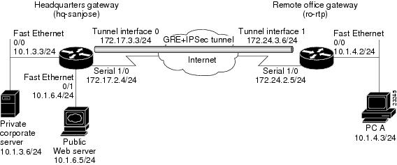
Figure 3-2 shows the physical elements of the scenario. The Internet provides the core interconnecting fabric between the headquarters and remote office routers. Both the headquarters and remote office are using a Cisco IOS VPN gateway (either a Cisco 7100 series with an Integrated Service Module (ISM) or VPN Accelerator Module (VAM), a Cisco 7200 series with an Integrated Service Adaptor (ISA) or VAM, a Cisco 2600 series, or a Cisco 3600 series router).
Note
The GRE tunnel is configured on the first serial interface in chassis slot 1 (serial 1/0) of the headquarters and remote office routers. Fast Ethernet interface 0/0 of the headquarters router is connected to a corporate server and Fast Ethernet interface 0/1 is connected to a web server. Fast Ethernet interface 0/0 of the remote office router is connected to a PC client.
Figure 3-2 Site-to-Site VPN Scenario Physical Elements
The configuration steps in the following sections are for the headquarters router, unless noted otherwise. Comprehensive configuration examples for both the headquarters and remote office routers are provided in the "Comprehensive Configuration Examples" section.
Table 3-1 lists the physical elements of the site-to-site scenario.
Extranet Scenario
The extranet scenario introduced in Figure 3-3 builds on the site-to-site scenario by providing a business partner access to the same headquarters network. In the extranet scenario, the headquarters and business partner are connected through a secure IPSec tunnel and the business partner is given access only to the headquarters public server to perform various IP-based network tasks, such as placing and managing product orders.
Figure 3-3 Extranet VPN Business Scenario
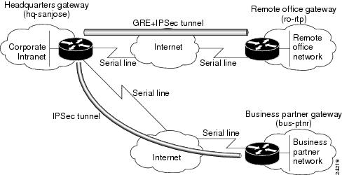
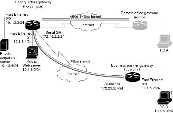
Figure 3-4 shows the physical elements of the scenario. As in the site-to-site business scenario, the Internet provides the core interconnecting fabric between the headquarters and business partner routers. Like the headquarters office, the business partner is also using a Cisco IOS VPN gateway (either a Cisco 7100 series with an Integrated Service Module (ISM) or a VPN Accelerator Module (VAM), a Cisco 7200 series with an Integrated Service Adaptor (ISA) or VAM, or a Cisco 3600 series concentrator).
Note
The IPSec tunnel between the two sites is configured on the second serial interface in chassis slot 2 (serial 2/0) of the headquarters router and the first serial interface in chassis slot 1 (serial 1/0) of the business partner router. Fast Ethernet interface 0/0 of the headquarters router is still connected to a private corporate server and Fast Ethernet interface 0/1 is connected to a public server. Fast Ethernet interface 0/0 of the business partner router is connected to a PC client.
Figure 3-4 Extranet VPN Scenario Physical Elements
The configuration steps in the following sections are for the headquarters router, unless noted otherwise. Comprehensive configuration examples for both the headquarters and business partner routers are provided in the "Comprehensive Configuration Examples" section.
Table 3-2 lists the extranet scenario's physical elements.
Table 3-2 Physical Elements
Address
Hardware
Addresshq-sanjose
Serial interface 2/0:
172.16.2.2
255.255.255.0Fast Ethernet
Interface 0/0:
10.1.3.3
255.255.255.0Fast Ethernet
Interface 0/1:
10.1.6.4
255.255.255.0bus-ptnr
Serial interface 1/0:
172.23.2.7
255.255.255.0Fast Ethernet
Interface 0/0:
10.1.5.2
255.255.255.0Corporate server
—
10.1.3.6
PC B
—
10.1.5.3
Web server
—
10.1.6.51
1 The inside local IP address of the headquarters network public server (10.1.6.5) is translated to inside global IP address 10.2.2.2 in the "Step 2—Configuring Network Address Translation" section.
Step 1—Configuring the Tunnel
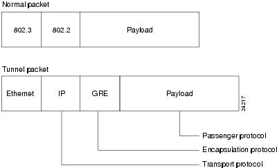
Tunneling provides a way to encapsulate packets inside of a transport protocol. Tunneling is implemented as a virtual interface to provide a simple interface for configuration. The tunnel interface is not tied to specific "passenger" or "transport" protocols, but rather, it is an architecture that is designed to provide the services necessary to implement any standard point-to-point encapsulation scheme. Because tunnels are point-to-point links, you must configure a separate tunnel for each link.
Tunneling has the following three primary components:
•
•
•
Figure 3-5 illustrates IP tunneling terminology and concepts.
Figure 3-5 IP Tunneling Terminology and Concepts
This section contains the following topics:
Configuring a GRE Tunnel
GRE is capable of handling the transportation of multiprotocol and IP multicast traffic between two sites, which only have IP unicast connectivity. The importance of using tunnels in a VPN environment is based on the fact that IPSec encryption only works on IP unicast frames. Tunneling allows for the encryption and the transportation of multiprotocol traffic across the VPN since the tunneled packets appear to the IP network as an IP unicast frame between the tunnel endpoints. If all connectivity must go through the home gateway router, tunnels also enable the use of private network addressing across a service provider's backbone without the need for running the Network Address Translation (NAT) feature.
Network redundancy (resiliency) is an important consideration in the decision to use GRE tunnels, IPSec tunnels, or tunnels which utilize IPSec over GRE. GRE can be used in conjunction with IPSec to pass routing updates between sites on an IPSec VPN. GRE encapsulates the clear text packet, then IPSec (in transport or tunnel mode) encrypts the packet.This packet flow of IPSec over GRE enables routing updates, which are generally multicast, to be passed over an encrypted link. IPSec alone can not achieve this, because it does not support multicast.
Using redundant GRE tunnels protected by IPSec from a remote router to redundant headquarter routers, routing protocols can be employed to delineate the "primary" and "secondary" headquarter routers. Upon loss of connectivity to the primary router, routing protocols will discover the failure and route to the secondary gateway, thereby providing network redundancy.
It is important to note that more than one router must be employed at HQ to provide resiliency. For VPN resilience, the remote site should be configured with two GRE tunnels, one to the primary HQ VPN router, and the other to the backup HQ VPN router.
This section contains basic steps to configure a GRE tunnel and includes the following tasks:
•
•
Configuring the Tunnel Interface, Source, and Destination
To configure a GRE tunnel between the headquarters and remote office routers, you must configure a tunnel interface, source, and destination on the headquarters and remote office routers. To do this, complete the following steps starting in global configuration mode.
Note
Step 1
hq-sanjose(config)#interface tunnel 0hq-sanjose(config-if)#ip address 172.17.3.3 255.255.255.0Specify a tunnel interface number, enter interface configuration mode, and configure an IP address and subnet mask on the tunnel interface. This example configures IP address and subnet mask 172.17.3.3 255.255.255.0 for tunnel interface 0 on the headquarters router.
Step 2
hq-sanjose(config-if)#tunnel source 172.17.2.4 255.255.255.0Specify the tunnel interface source address and subnet mask. This example uses the IP address and subnet mask of T3 serial interface 1/0 of the headquarters router.
Step 3
hq-sanjose(config-if)#tunnel destination 172.24.2.5 255.255.255.0Specify the tunnel interface destination address. This example uses the IP address and subnet mask of T3 serial interface 1/0 of the remote office router.
Step 4
hq-sanjose(config-if)#tunnel mode gre ipConfigure GRE as the tunnel mode.
GRE is the default tunnel encapsulation mode, so this command is considered optional.
Step 5
hq-sanjose(config)#interface tunnel 0hq-sanjose(config-if)#no shutdown%LINK-3-UPDOWN: Interface Tunnel0, changed state to upBring up the tunnel interface.1
Step 6
hq-sanjose(config-if)#exithq-sanjose(config)#ip route 10.1.4.0 255.255.255.0 tunnel 0Exit back to global configuration mode and configure traffic from the remote office network through the tunnel. This example configures traffic from the remote office Fast Ethernet network (10.1.4.0 255.255.255.0) through GRE tunnel 0.
1 This command changes the state of the tunnel interface from administratively down to up.
Note
Verifying the Tunnel Interface, Source, and Destination
To verify the configuration:
•
hq-sanjose# show interfaces tunnel 0Tunnel0 is up, line protocol is upHardware is TunnelInternet address is 172.17.3.3/24MTU 1514 bytes, BW 180 Kbit, DLY 500000 usec,reliablility 255/255, txload 1/255, rxload 1/255Encapsulation TUNNEL, loopback not setKeepalive set (10 sec)Tunnel source 172.17.2.4, destination 172.24.2.5Tunnel protocol/transport GRE/IP, key disabled, sequencing disabledChecksumming of packets disabled, fast tunneling enabledLast input never, output 00:10:44, output hang neverLast clearing of "show interface" counters neverQueueing strategy:fifoOutput queue 0/0, 0 drops; input queue 0/75, 0 drops5 minute input rate 0 bits/sec, 0 packets/sec5 minute output rate 0 bits/sec, 0 packets/sec0 packets input, 0 bytes, 0 no bufferReceived 0 broadcasts, 0 runts, 0 giants, 0 throttles0 input errors, 0 CRC, 0 frame, 0 overrun, 0 ignored, 0 abort29 packets output, 2348 bytes, 0 underruns0 output errors, 0 collisions, 0 interface resets0 output buffer failures, 0 output buffers swapped out•
hq-sanjose(config)# ping 172.24.3.6Type escape sequence to abort.Sending 5, 100-byte ICMP Echos to 172.24.3.6, timeout is 2 seconds:!!!!!Success rate is 100 percent (5/5), round-trip min/avg/max = 4/5/8 ms
Tips
Configuring an IPSec Tunnel
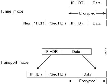
IPSec can be configured in tunnel mode or transport mode. IPSec tunnel mode can be used as an alternative to a GRE tunnel, or in conjunction with a GRE tunnel. In IPSec tunnel mode, the entire original IP datagram is encrypted, and it becomes the payload in a new IP packet. This mode allows a network device, such as a router, to act as an IPSec proxy. That is, the router performs encryption on behalf of the hosts. The source router encrypts packets and forwards them along the IPSec tunnel. The destination router decrypts the original IP datagram and forwards it on to the destination system. Tunnel mode protects against traffic analysis; with tunnel mode, an attacker can only determine the tunnel endpoints and not the true source and destination of the packets passing through the tunnel, even if they are the same as the tunnel endpoints.
Note
In IPSec transport mode, only the IP payload is encrypted, and the original IP headers are left intact. (See Figure 3-6.) This mode has the advantage of adding only a few bytes to each packet. It also allows devices on the public network to see the final source and destination of the packet. With this capability, you can enable special processing in the intermediate network based on the information in the IP header. However, the Layer 4 header will be encrypted, limiting the examination of the packet. Unfortunately, by passing the IP header in the clear, transport mode allows an attacker to perform some traffic analysis. (See the "Defining Transform Sets and Configuring IPSec Tunnel Mode" section for an IPSec transport mode configuration example.)
Figure 3-6 IPSec in Tunnel and Transport Modes
Step 2—Configuring Network Address Translation
Note
Network Address Translation (NAT) enables private IP internetworks with addresses that are not globally unique to connect to the Internet by translating those addresses into globally routable address space. NAT is configured on the router at the border of a stub domain (referred to as the inside network) and a public network such as the Internet (referred to as the outside network). NAT translates the internal local addresses to globally unique IP addresses before sending packets to the outside network. NAT also allows a more graceful renumbering strategy for organizations that are changing service providers or voluntarily renumbering into classless interdomain routing (CIDR) blocks.
This section only explains how to configure static translation to translate internal local IP addresses into globally unique IP addresses before sending packets to an outside network, and includes the following tasks:
•
•
Static translation establishes a one-to-one mapping between your internal local address and an inside global address. Static translation is useful when a host on the inside must be accessible by a fixed address from the outside.
Note
NAT uses the following definitions:
•
•
•
•
Figure 3-7 illustrates a router that is translating a source address inside a network to a source address outside the network.
Figure 3-7 NAT Inside Source Translation
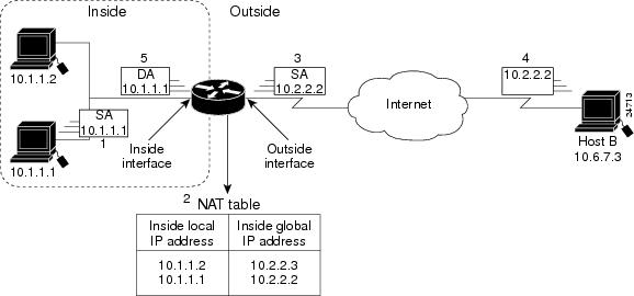
The following process describes inside source address translation, as shown in Figure 3-7:
1.
2.
If a static translation entry was configured, the router goes to Step 3.
If no translation entry exists, the router determines that source address (SA) 10.1.1.1 must be translated dynamically, selects a legal, global address from the dynamic address pool, and creates a translation entry. This type of entry is called a simple entry.
3.
4.
5.
6.
This section contains the following topics:
•
•
Configuring Static Inside Source Address Translation
To configure static inside source address translation, complete the following steps starting in global configuration mode:
The previous steps are the minimum you must configure for static inside source address translation. You could configure multiple inside and outside interfaces.
Verifying Static Inside Source Address Translation
To verify the configuration:
•
hq-sanjose# show ip nat translations verbosePro Inside global Inside local Outside local Outsideglobal--- 10.2.2.2 10.1.6.5 --- ---create 00:10:28, use 00:10:28, flags:static•
hq-sanjose# show running-configinterface FastEthernet0/1ip address 10.1.6.5 255.255.255.0no ip directed-broadcastip nat insideinterface serial2/0ip address 172.16.2.2 255.255.255.0ip nat outsideip nat inside source static 10.1.6.5 10.2.2.2Step 3—Configuring Encryption and IPSec
IPSec is a framework of open standards, developed by the Internet Engineering Task Force (IETF), that provides data confidentiality, data integrity, and data authentication between participating peers. IPSec provides these security services at the IP layer; it uses IKE to handle negotiation of protocols and algorithms based on local policy, and to generate the encryption and authentication keys to be used by IPSec. IPSec can be used to protect one or more data flows between a pair of hosts, between a pair of security gateways, or between a security gateway and a host.
IKE is a hybrid security protocol that implements Oakley and SKEME key exchanges inside the Internet Security Association and Key Management Protocol (ISAKMP) framework. While IKE can be used with other protocols, its initial implementation is with the IPSec protocol. IKE provides authentication of the IPSec peers, negotiates IPSec security associations, establishes IPSec keys, and provides IKE keepalives. IPSec can be configured without IKE, but IKE enhances IPSec by providing additional features, flexibility, ease of configuration for the IPSec standard, and keepalives, which are integral in achieving network resilience when configured with GRE.
Certification authority (CA) interoperability is provided by the ISM in support of the IPSec standard. It permits Cisco IOS devices and CAs to communicate so that your Cisco IOS device can obtain and use digital certificates from the CA. Although IPSec can be implemented in your network without the use of a CA, using a CA provides manageability and scalability for IPSec.
The CA must be properly configured to issue certificates. You must also configure the peers to obtain certificates from the CA. Configure this certificate support as described in the "Configuring Certification Authority Interoperability" chapter of the Security Configuration Guide.
To provide encryption and IPSec tunneling services on a Cisco IOS VPN gateway, you must complete the following tasks:
•
Note
Optionally, you can configure CA interoperability. This guide does not explain how to configure CA interoperability on your Cisco IOS VPN gateway. Refer to the "IP Security and Encryption" part of the Security Configuration Guide and the Security Command Reference publications for detailed information on configuring CA interoperabilty.
Note
Refer to the Integrated Service Adapter and Integrated Service Module Installation and Configuration publication for detailed configuration information on the ISM.
This section contains the following topics:
•
Configuring IKE Policies
Internet Key Exchange (IKE) is enabled by default. IKE does not have to be enabled for individual interfaces, but is enabled globally for all interfaces in the router. You must create IKE policies at each peer. An IKE policy defines a combination of security parameters to be used during the IKE negotiation.
You can create multiple IKE policies, each with a different combination of parameter values. If you do not configure any IKE policies, the router uses the default policy, which is always set to the lowest priority, and which contains each parameter default value.
For each policy that you create, you assign a unique priority (1 through 10,000, with 1 being the highest priority). You can configure multiple policies on each peer—but at least one of these policies must contain exactly the same encryption, hash, authentication, and Diffie-Hellman parameter values as one of the policies on the remote peer. If you do not specify a value for a parameter, the default value is assigned.
IKE keepalives (or "hello packets") are required to detect a loss of connectivity, providing network resiliency. If your HQ employs more than two routers and utilizes IPSec, you can specify the length of keepalive packets or use the default time period of 10 seconds. To specify the interval length at which keepalive packets are to be sent, use the cry isakmp keepalive
command, as exemplified in Step 2 of the "Creating IKE Policies" section.
Note
This section contains basic steps to configure IKE policies and includes the following tasks:
•
Creating IKE Policies
To create an IKE policy, complete the following steps starting in global configuration mode:
Step 1
hq-sanjose(config)#crypto isakmp policy 1Enter config-isakmp command mode and identify the policy to create. (Each policy is uniquely identified by the priority number you assign.) This example configures policy 1.
Step 2
hq-sanjose(config)#cry isakmp keepalive 12 2Optional step: Specify the time interval of IKE keepalive packets (default is 10 seconds), and the retry interval when the keepalive packet failed. This example configures the keepalive interval for 12 seconds and the retry interval for 2 seconds.
Step 3
hq-sanjose(config-isakmp)#encryption desSpecify the encryption algorithm—56-bit Data Encryption Standard (DES [des]) or 168-bit Triple DES (3des). This example configures the DES algorithm, which is the default.
Step 4
hq-sanjose(config-isakmp)#hash shaSpecify the hash algorithm—Message Digest 5 (MD5 [md5]) or Secure Hash Algorithm (SHA [sha]). This example configures SHA, which is the default.
Step 5
hq-sanjose(config-isakmp)#authentication pre-shareSpecify the authentication method—pre-shared keys (pre-share), RSA1 encrypted nonces (rsa-encr), or RSA signatures (rsa-slg). This example configures pre-shared keys. The default is RSA signatures.
Step 6
hq-sanjose(config-isakmp)#group 1Specify the Diffie-Hellman group identifier—768-bit Diffie-Hellman (1) or 1024-bit Diffie-Hellman (2). This example configures 768-bit Diffie-Hellman, which is the default.
Step 7
hq-sanjose(config-isakmp)#lifetime 86400Specify the security association's lifetime—in seconds. This example configures 86400 seconds (one day).
Step 8
hq-sanjose(config-isakmp)#exithq-sanjose(config)#Exit back to global configuration mode.
1 RSA = Rivest, Shamir, and Adelman.
Additional Configuration Required for IKE Policies
Depending on which authentication method you specify in your IKE policies, you need to complete an additional companion configuration before IKE and IPSec can successfully use the IKE policies.
Each authentication method requires an additional companion configuration as follows:
•
If you specify RSA signatures as the authentication method in a policy, you must configure the peers to obtain certificates from a certification authority (CA). (And, of course, the CA must be properly configured to issue the certificates.) Configure this certificate support as described in the "Configuring Certification Authority Interoperability" chapter of the Security Configuration Guide.
The certificates are used by each peer to securely exchange public keys. (RSA signatures require that each peer has the remote peer's public signature key.) When both peers have valid certificates, they will automatically exchange public keys with each other as part of any IKE negotiation in which RSA signatures are used.
•
If you specify RSA encrypted nonces as the authentication method in a policy, you need to ensure that each peer has the other peers' public keys.
Unlike RSA signatures, the RSA encrypted nonces method does not use certificates to exchange public keys. Instead, you ensure that each peer has the others' public keys by doing the following:
–
–
To make this happen, specify two policies: a higher-priority policy with RSA encrypted nonces, and a lower-priority policy with RSA signatures. When IKE negotiations occur, RSA signatures will be used the first time because the peers do not yet have each others' public keys. Then, future IKE negotiations will be able to use RSA-encrypted nonces because the public keys will have been exchanged.
Of course, this alternative requires that you have CA support configured.
•
If you specify pre-shared keys as the authentication method in a policy, you must configure these pre-shared keys as described in the "Configuring Pre-shared Keys" section."
•
If you specify digital certificates as the authentication method in a policy, the CA must be properly configured to issue certificates. You must also configure the peers to obtain certificates from the CA. Configure this certificate support as described in the "Configuring Certification Authority Interoperability" chapter of the Security Configuration Guide.
Digital certificates simplify authentication. You need only enroll each peer with the CA, rather than manually configuring each peer to exchange keys. Cisco recommends using digital certificates in a network of more than 50 peers. Third party CAs include Microsoft, Verisign, Baltimore, and Entrust.
If RSA encryption is configured and signature mode is negotiated, the peer will request both signature and encryption keys. Basically, the router will request as many keys as the configuration will support. If RSA encryption is not configured, it will just request a signature key.
Configuring Pre-shared Keys
To configure pre-shared keys, perform these steps at each peer that uses pre-shared keys in an IKE policy:
Step 1
Step 2

Note
To specify pre-shared keys at a peer, complete the following steps in global configuration mode:
Note
Configuring the Gateway for Digital Certificate Interoperability
To configure your IOS gateway to use digital certificates as the authentication method, use the following steps, beginning in global configuration mode. This configuration assumes the use of the IOS default ISAKMP policy, which uses DES, SHA, RSA signatures, Diffie-Hellman group 1, and a lifetime of 86,400 seconds. Cisco recommends using 3DES. Refer to the "Creating IKE Policies" section for an ISAKMP configuration example which specifies 3DES as the encryption method.
Note
Verifying IKE Policies
To verify the configuration:
•
hq-sanjose# show crypto isakmp policyProtection suite priority 1encryption algorithm: DES - Data Encryption Standard (56 bit keys)hash algorithm: Secure Hash Standardauthentication method: Pre-Shared KeyDiffie-Hellman group: #1 (768 bit)lifetime: 86400 seconds, no volume limit
Note
Tips
hq-sanjose# show versionCisco Internetwork Operating System SoftwareIOS (tm) EGR Software (c7100-JOS56I-M), Release Version 12.0(4)XECopyright (c) 1986-1999 by cisco Systems, Inc.Compiled Mon 22-Mar-99 21:41 by biffImage text-base:0x600088F8, data-base:0x611CE000ROM:System Bootstrap, Version 12.0(4)XE RELEASE SOFTWARErouter uptime is 20 hours, 34 minutesSystem restarted by reload at 22:36:57 PST Fri Dec 31 1999System image file is "c7100-jos56i-mz"cisco 7140 (EGR) processor with 188416K/139264K bytes of memory.R7000 CPU at 262Mhz, Implementation 39, Rev 1.0, 256KB L2, 2048KB L3 CacheLast reset from power-onBridging software.X.25 software, Version 3.0.0.SuperLAT software copyright 1990 by Meridian Technology Corp).TN3270 Emulation software.3 FastEthernet/IEEE 802.3 interface(s)2 Serial network interface(s)125K bytes of non-volatile configuration memory.40960K bytes of ATA PCMCIA card at slot 0 (Sector size 512 bytes).8192K bytes of Flash internal SIMM (Sector size 256K).Configuration register is 0x0Configuring a Different Shared Key
Because pre-shared keys were specified as the authentication method for policy 1 in the "Configuring IKE Policies" section, (the policy that will also be used on the business partner router) complete the following steps at the headquarters router as well as the business partner router:
Step 1
Step 2

Note
To configure a different pre-shared key for use between the headquarters router and the business partner router, complete the following steps in global configuration mode:
Step 1
hq-sanjose(config)#crypto isakmp key test67890 address 172.23.2.7At the local peer: Specify the shared key the headquarters router will use with the business partner router. This example configures the shared key test67890 to be used with the remote peer 172.23.2.7 (serial interface 1/0 on the business partner router).
Step 2
bus-ptnr(config)#crypto isakmp identity addressAt the remote peer: Specify the ISAKMP identity (address or hostname) the business partner router will use when communicating with the headquarters router during IKE negotiations. (This task was already completed on the headquarters router when policy 1 was configured in the "Configuring IKE Policies" section.) This example specifies the address keyword, which uses IP address 172.23.2.7 (serial interface 1/0 of the business partner router) as the identity for the business partner router.
Step 3
bus-ptnr(config)#crypto isakmp key test67890 address 172.17.2.4At the remote peer: Specify the shared key to be used with the local peer. This is the same key you just specified at the local peer. This example configures the shared key test67890 to be used with the local peer 172.16.2.2 (serial interface 2/0 on the headquarters router).
Note
Configuring IPSec and IPSec Tunnel Mode
After you have configured a different shared key, configure IPSec at each participating IPSec peer. This section contains basic steps to configure IPSec and includes the following tasks:
•
•
•
Note
Creating Crypto Access Lists
Crypto access lists are used to define which IP traffic will be protected by crypto and which traffic will not be protected by crypto. (These access lists are not the same as regular access lists, which determine what traffic to forward or block at an interface.) For example, you can create access lists to protect all IP traffic between the headquarters router and business partner router.
The access lists themselves are not specific to IPSec. It is the crypto map entry referencing the specific access list that defines whether IPSec processing is applied to the traffic matching a permit in the access list.
To create a crypto access list, enter the following command in global configuration mode:
hq-sanjose(config)#access-list 111 permit ip host 10.2.2.2 host 10.1.5.3Specify conditions to determine which IP packets are protected.1 (Enable or disable crypto for traffic that matches these conditions.) This example configures access list 111 to encrypt all IP traffic between the headquarters server (translated inside global IP address 10.2.2.2) and PC B (IP address 10.1.5.3) in the business partner office.
We recommend that you configure "mirror image" crypto access lists for use by IPSec and that you avoid using the any keyword.
1 You specify conditions using an IP access list designated by either a number or a name. The access-list command designates a numbered extended access list; the ip access-list extended command designates a named access list.
Verifying Crypto Access Lists
To verify the configuration:
•
hq-sanjose# show access-lists 111Extended IP access list 111permit ip host 10.2.2.2 host 10.1.5.3
Tips
Defining Transform Sets and Configuring IPSec Tunnel Mode
You must define transform sets regardless of the tunneling protocol you use. To define a transform set and configure IPSec tunnel mode, complete the following steps starting in global configuration mode:
Step 1
hq-sanjose(config)#crypto ipsec transform-set proposal4 ah-sha-hmac esp-desDefine a transform set and enter crypto-transform configuration mode. This example combines AH1 transform ah-sha-hmac, ESP2 encryption transform esp-des, and ESP authentication transform esp-sha-hmac in the transform set proposal4.
There are complex rules defining which entries you can use for the transform arguments. These rules are explained in the command description for the crypto ipsec transform-set command. You can also use the crypto ipsec transform-set? command, in global configuration mode, to view the available transform arguments.
Step 2
hq-sanjose(cfg-crypto-trans)#mode tunnelChange the mode associated with the transform set. The mode setting is only applicable to traffic whose source and destination addresses are the IPSec peer addresses; it is ignored for all other traffic. (All other traffic is in tunnel mode only.) This example configures tunnel mode for the transport set proposal4, which creates an IPSec tunnel between the IPSec peer addresses.
Step 3
hq-sanjose(cfg-crypto-trans)#exithq-sanjose(config)#Exit back to global configuration mode.
1 AH = authentication header. This header, when added to an IP datagram, ensures the integrity and authenticity of the data, including the invariant fields in the outer IP header. It does not provide confidentiality protection. AH uses a keyed-hash function rather than digital signatures.
2 ESP = encapsulating security payload. This header, when added to an IP datagram, protects the confidentiality, integrity, and authenticity of the data. If ESP is used to validate data integrity, it does not include the invariant fields in the IP header.
Note
Verifying Transform Sets and IPSec Tunnel Mode
To verify the configuration:
•
hq-sanjose# show crypto ipsec transform-setTransform set proposal4: { ah-sha-hmac }will negotiate = { Tunnel, },{ esp-des esp-sha-hmac }will negotiate = { Tunnel, },-Display text omitted-Configuring Crypto Maps
Remote devices need to be managed through a VPN from the central site when operating on a centralized IT model. VPN devices support numerous configuration options to determine the tunnel endpoint and, depending on the method chosen, these options may impact the manageability of the network. Refer to the "Dynamic versus Static Crypto Maps" section for a discussion of when to use static or dynamic crypto maps.
To be the most effective in managing remote devices, you must use static cryptographic maps at the site where your management applications are located. Dynamic cryptographic maps can be used at the headend for ease of configuration. Dynamic maps, however, accept only incoming IKE requests, and because dynamic maps cannot initiate an IKE request, it is not always guaranteed that a tunnel exists between the remote device and the headend site. Static cryptographic map configuration includes the static IP addresses of the remote peers. Thus, remote sites must use static IP addresses to support remote management.
For IPSec to succeed between two IPSec peers, both peer crypto map entries must contain compatible configuration statements.
When two peers try to establish a security association (SA), they must each have at least one crypto map entry that is compatible with one of the other peer crypto map entries. For two crypto map entries to be compatible, they must meet the following minimum criteria:
•
•
•
When IKE is used to establish SAs, the IPSec peers can negotiate the settings they will use for the new SAs. This means that you can specify lists (such as lists of acceptable transforms) within the crypto map entry.
After you have completed configuring IPSec at each participating IPSec peer, configure crypto map entries and apply the crypto maps to interfaces.
The task of configuring IPSec at each peer can be eased by utilizing dynamic crypto maps. By configuring the head-end gateway with a dynamic map, and the peers with a static map, the peer will be permitted to establish an IPSec security association even though the router does not have a crypto map entry specifically configured to meet all of the remote peer requirements.
This section contains basic steps to configure crypto maps and includes the following tasks:
•
•
Creating Crypto Map Entries
To create crypto map entries that will use IKE to establish the SAs, complete the following steps starting in global configuration mode:
Step 1
hq-sanjose(config)#crypto map s4second local-address serial 2/0Create the crypto map and specify a local address (physical interface) to be used for the IPSec traffic. This example creates crypto map s4second and specifies serial interface 2/0 of the headquarters router as the local address. This step is only required if you have previously used the loopback command or if you are using GRE tunnels.
Step 2
hq-sanjose(config)#crypto map s4second 2 ipsec-isakmpEnter crypto map configuration mode, specify a sequence number for the crypto map you created in Step 1, and configure the crypto map to use IKE to establish SAs. This example configures sequence number 2 and IKE for crypto map s4second.
Step 3
hq-sanjose(config-crypto-map)#match address 111Specify an extended access list. This access list determines which traffic is protected by IPSec and which traffic is not be protected by IPSec. This example configures access list 111, which was created in the "Creating Crypto Access Lists" section.
Step 4
hq-sanjose(config-crypto-map)#set peer 172.23.2.7Specify a remote IPSec peer (by host name or IP address). This is the peer to which IPSec protected traffic can be forwarded. This example specifies serial interface 1/0 (172.23.2.7) on the business partner router.
Step 5
hq-sanjose(config-crypto-map)#set transform-set proposal4Specify which transform sets are allowed for this crypto map entry. List multiple transform sets in order of priority (highest priority first). This example specifies transform set proposal4, which was configured in the "Defining Transform Sets and Configuring IPSec Tunnel Mode" section.
Step 6
hq-sanjose(config-crypto-map)#exithq-sanjose(config)#Exit back to global configuration mode.
To create dynamic crypto map entries that will use IKE to establish the SAs, complete the following steps, starting in global configuration mode:
Verifying Crypto Map Entries
To verify the configuration:
•
In the following example, peer 172.23.2.7 is the IP address of the remote IPSec peer. "Extended IP access list 111" lists the access list associated with the crypto map. "Current peer" indicates the current IPSec peer. "Security-association lifetime" indicates the lifetime of the SA.
"PFS N" indicates that IPSec will not negotiate perfect forward secrecy when establishing new SAs for this crypto map. "Transform sets" indicates the name of the transform set that can be used with the crypto map.
hq-sanjose# show crypto mapCrypto Map: "s4second" idb: Serial2/0 local address: 172.16.2.2Crypto Map "s4second" 2 ipsec-isakmpPeer = 172.23.2.7Extended IP access list 111access-list 111 permit ipsource: addr = 10.2.2.2/255.255.255.0dest: addr = 10.1.5.3/255.255.255.0SCurrent peer: 172.23.2.7Security-association lifetime: 4608000 kilobytes/3600 secondsPFS (Y/N): NTransform sets={proposal4,}-Display text omitted-
Tips
Applying Crypto Maps to Interfaces
You need to apply a crypto map set to each interface through which IPSec traffic will flow. Applying the crypto map set to an interface instructs the router to evaluate all the interface traffic against the crypto map set, and to use the specified policy during connection or SA negotiation on behalf of traffic to be protected by crypto.
To apply a crypto map set to an interface, complete the following steps starting in global configuration mode:
Step 1
hq-sanjose(config)#interface serial 2/0Specify a physical interface on which to apply the crypto map and enter interface configuration mode. This example specifies serial interface 2/0 on the headquarters router.
Step 2
hq-sanjose(config-if)#crypto map s4secondApply the crypto map set to the physical interface. This example configures crypto map s4second, which was created in the "Creating Crypto Map Entries" section.
Step 3
hq-sanjose(config-if)#exithq-sanjose(config)#Exit back to global configuration mode.
Step 4
hq-sanjose#clear crypto saIn privileged EXEC mode, clear the existing IPSec SAs so that any changes are used immediately. (Manually established SAs are reestablished immediately.)
Note
Verifying Crypto Map Interface Associations
To verify the configuration:
•
hq-sanjose# show crypto map interface serial 2/0Crypto Map "s4second" 2 ipsec-isakmpPeer = 172.23.2.7Extended IP access list 111access-list 111 permit ip host 10.2.2.2 host 10.1.5.3Current peer:172.23.2.7Security association lifetime:4608000 kilobytes/1000 secondsPFS (Y/N):NTransform sets={ proposal4, }Step 4—Configuring Quality of Service
Cisco IOS quality of service (QoS) refers to the ability of a network to provide better service to selected network traffic over various underlying technologies including Frame Relay, Asynchronous Transfer Mode (ATM), Ethernet and 802.1 networks, SONET, and IP-routed networks. In particular, QoS features provide better and more predictable network service by:
•
•
•
•
•
You configure QoS features throughout a network to provide for end-to-end QoS delivery. The following three components are necessary to deliver QoS across a heterogeneous network:
•
•
•
Not all QoS techniques are appropriate for all network routers. Because edge routers and backbone routers in a network do not necessarily perform the same operations, the QoS tasks they perform might differ as well.
In general, edge routers perform the following QoS functions:
•
•
•
In general, backbone routers perform the following QoS functions:
•
•
Cisco IOS QoS service models, features, and sample configurations are explained in detail in the Quality of Service Solutions Configuration Guide and the Quality of Service Solutions Command Reference. Refer to these two publications as you plan and implement a QoS strategy for your VPN, because there are various QoS service models and features that you can implement on your VPN.
This section contains basic steps to configure QoS weighted fair queuing (WFQ), which applies priority (or weights) to identified traffic on the GRE tunnel you configured in the "Step 1—Configuring the Tunnel" section. This section also contains basic steps to configure Network-Based Application Recognition (NBAR), which is a classification engine that recognizes a wide variety of applications, including web-based and other protocols that utilize dynamic TCP/UDP port assignments.
This section includes the following topics:
•
•
•
•
•
Configuring Network-Based Application Recognition
Network-Based Application Recognition (NBAR) adds intelligent network classification to network infrastructures. NBAR is a classification engine that recognizes a wide variety of applications, including web-based and other protocols that utilize dynamic TCP/UDP port assignments. When an application is recognized and classified by NBAR, a network can invoke services for that specific application. NBAR ensures that network bandwidth is used efficiently by working with QoS features.
Your interface to NBAR is through the modular QoS command-line interface (MQC). MQC provides a model for QoS configuration under IOS. MQC provides a clean separation between the specification of a classification policy and the specification of other policies that act based on the results of the applied classification.
Configuring a QoS policy typically requires the configuration of traffic classes, the configuration of policies that will be applied to those traffic classes, and the attaching of policies to interfaces using the commands in the sections that follow.
The following tasks are required to configure NBAR:
•
•
•
Note
Configuring a Class Map
Use the class-map configuration command to define a traffic class and the match criteria that will be used to identify traffic as belonging to that class. Match statements can include criteria such as protocol, ACL, IP precedence value, or interface identifier. The match criteria is defined with one or more of the match statements entered within the class-map configuration mode listed in the table below:
Step 1
Specifies the user-defined name of the class map. The match-all option specifies that all match criteria in the class map must be matched. The match-any option specifies that one or more match criteria must match.1
Step 2
Specifies a protocol supported by NBAR as a matching criteria.
Step 3
Specifies a class map as a matching criteria (nested class maps).
1 When neither match-all nor match-any is specified, the default is match-all. Use the no class-map command to disable the class map. Use the no match-all and no match-any commands to disable these commands within the class map. Use the match not command to configure a match that evaluates to true if the packet does not match the specified protocol.
Verifying a Class Map Configuration
Enter the show class-map command to display all class map information. You can also enter the show class-map class-name command to display the class map information of a user-specified class map.
Configuring a Policy Map
Use the policy-map configuration command to specify the QoS policies to apply to traffic classes defined by a class map. QoS policies that can be applied to traffic classification are listed in the table below.
Use the no policy-map command to deconfigure the policy map. Use the no bandwidth, no police, no set, and no random-detect commands to disable these commands within the policy map.
Attaching a Policy Map to an Interface
Use the service-policy interface configuration command to attach a policy map to an interface and to specify the direction in which the policy should be applied (on either packets coming into the interface or packets leaving the interface).
Use the no service-policy [input | output] policy-map-name command to detach a policy map from an interface.
Verifying a Policy Map Configuration
Use the show policy-map [interface [interface-spec [input | output [class class-name]]]] command to display the configuration of a policy map and its associated class maps. Forms of this command are listed in the following table:
Configuring Weighted Fair Queuing
Weighted Fair Queuing (WFQ) provides traffic priority management that automatically sorts among individual traffic streams without requiring that you first define access lists. WFQ can also manage duplex data streams such as those between pairs of applications, and simplex data streams such as voice or video. There are two categories of WFQ sessions: high bandwidth and low bandwidth. Low-bandwidth traffic has effective priority over high-bandwidth traffic, and high-bandwidth traffic shares the transmission service proportionally according to assigned weights.
When WFQ is enabled for an interface, new messages for high-bandwidth traffic streams are discarded after the configured or default congestive messages threshold has been met. However, low-bandwidth conversations, which include control message conversations, continue to enqueue data. As a result, the fair queue may occasionally contain more messages than its configured threshold number specifies.
With standard WFQ, packets are classified by flow. Packets with the same source IP address, destination IP address, source Transmission Control Protocol (TCP) or User Datagram Protocol (UDP) port, or destination TCP or UDP port belong to the same flow. WFQ allocates an equal share of the bandwidth to each flow. Flow-based WFQ is also called fair queuing because all flows are equally weighted.
To configure fair queuing on an interface, complete the following steps starting in global configuration mode:
Verifying Weighted Fair Queuing
To verify the configuration:
•
hq-sanjose# show interfaces serial 1/0 fair-queueSerial1/0 queue size 0packets output 35, drops 0WFQ: global queue limit 401, local queue limit 200•
hq-sanjose# show interfaces serial 1/0Serial1/0 is up, line protocol is upHardware is M2T-T3 pa-Display text omitted-Queueing strategy:weighted fairOutput queue:0/1000/64/0 (size/max total/threshold/drops)Conversations 0/0/256 (active/max active/max total)Reserved Conversations 0/0 (allocated/max allocated)-Display text omitted-Configuring Class-Based Weighted Fair Queuing
Class-based weighted fair queueing (CBWFQ) extends the standard WFQ functionality to provide support for user-defined traffic classes. For CBWFQ, you define traffic classes based on match criteria including protocols, access control lists (ACLs), and input interfaces. Packets satisfying the match criteria for a class constitute the traffic for that class. A queue is reserved for each class, and traffic belonging to a class is directed to that class queue.
Once a class has been defined according to its match criteria, you can assign it characteristics. To characterize a class, you assign it bandwidth, weight, and maximum packet limit. The bandwidth assigned to a class is the minimum bandwidth delivered to the class during congestion.
To characterize a class, you also specify the queue limit for that class, which is the maximum number of packets allowed to accumulate in the class queue. Packets belonging to a class are subject to the bandwidth and queue limits that characterize the class.
After a queue has reached its configured queue limit, enqueuing of additional packets to the class causes tail drop or packet drop to take effect, depending on how class policy is configured.
Tail drop is used for CBWFQ classes unless you explicitly configure policy for a class to use weighted random early detection (WRED) to drop packets as a means of avoiding congestion. Note that if you use WRED packet drop instead of tail drop for one or more classes comprising a policy map, you must ensure that WRED is not configured for the interface to which you attach that service policy.
Note
If a default class is configured, all unclassified traffic is treated as belonging to the default class. If no default class is configured, then by default the traffic that does not match any of the configured classes is flow classified and given best-effort treatment. Once a packet is classified, all of the standard mechanisms that can be used to differentiate service among the classes apply.
Flow classification is standard WFQ treatment. That is, packets with the same source IP address, destination IP address, source Transmission Control Protocol (TCP) or User Datagram Protocol (UDP) port, or destination TCP or UDP port are classified as belonging to the same flow. WFQ allocates an equal share of bandwidth to each flow. Flow-based WFQ is also called fair queueing because all flows are equally weighted.
For CBWFQ, which extends the standard WFQ, the weight specified for the class becomes the weight of each packet that meets the match criteria of the class. Packets that arrive at the output interface are classified according to the match criteria filters you define, then each one is assigned the appropriate weight.
The weight for a packet belonging to a specific class is derived from the bandwidth you assigned to the class when you configured it; in this sense the weight for a class is user-configurable.
After a packet's weight is assigned, the packet is enqueued in the appropriate class queue. CBWFQ uses the weights assigned to the queued packets to ensure that the class queue is serviced fairly.
The following tasks are required to configure CBWFQ:
•
•
•
Note
Defining a Class Map
To create a class map containing match criteria against which a packet is checked to determine if it belongs to a class, and to effectively create the class whose policy can be specified in one or more policy maps, use the first command in global configuration mode to specify the class-map name. Then use one of the following commands in class-map configuration mode:
Configuring Class Policy in the Policy Map (Tail Drop)
To configure a policy map and create class policies (including a default class) comprising the service policy, use the first global configuration command to specify the policy-map name. Then use the following policy-map configuration commands to configure policy for a standard class and the default class. For each class that you define, you can use one or more of the following policy-map configuration commands to configure class policy. For example, you might specify bandwidth for one class and both bandwidth and queue limit for another class.
The policy-map default class is the class to which traffic is directed if that traffic does not satisfy the match criteria of other classes whose policy is defined in the policy map. To configure policy for more than one class in the same policy map, repeat Steps 2 through 4. Note that because this set of commands uses queue-limit, the policy map uses tail drop for both class policies, not WRED packet drop.
To attach a service policy to an interface and enable CBWFQ on the interface, you must create a policy map. You can configure class policies for as many classes as are defined on the router up to the maximum of 64.
Attaching the Service Policy and Enabling CBWFQ
To attach a service policy to the output interface and enable CBWFQ on the interface, use the interface configuration command in the following table:
hq-sanjose(config-if)#service-policy output policy-mapEnables CBWFQ and attaches the specified service policy map to the output interface.
Note
Verifying Class-Based Weighted Fair Queuing
To display the contents of a specific policy map, a specific class from a specific policy map, or all policy maps configured on an interface, use one of the following global configuration commands:
Step 5—Configuring Cisco IOS Firewall Features
Cisco IOS software provides an extensive set of security features with which you can configure a simple or elaborate firewall, according to your particular requirements. When you configure Cisco IOS firewall features on your Cisco router, you turn your router into an effective, robust firewall.
Cisco IOS firewall features are designed to prevent unauthorized, external individuals from gaining access to your internal network, and to block attacks on your network, while at the same time allowing authorized users to access network resources.
Note
Note
You can use Cisco IOS firewall features to configure your Cisco IOS router as:
•
•
•
•
Cisco IOS firewall features provide the following benefits:
•
•
•
At a minimum, you must configure basic traffic filtering to provide a basic firewall. You can configure your Cisco IOS gateway to function as a firewall by using the following Cisco IOS security features:
•
•
•
•
•
•
•
•
•
•
•
•
Note
This section explains how to configure an extended access list, which is a sequential collection of permit and deny conditions that apply to an IP address.
This section includes the following topics:
•
•
•
•
Note
The simplest connectivity to the Internet is to use a single device to provide the connectivity and firewall function to the Internet. With everything being in a single device, it is easy to address translation and termination of the VPN tunnels. Complexity arises when you need to add extra VPN gateways to the network. This normally leads people into building a network where the corporate network touches the Internet through a network called the DMZ, or demilitarized zone.
Creating Extended Access Lists Using Access List Numbers
To create an extended access list that denies and permits certain types of traffic, complete the following steps starting in global configuration mode:
Verifying Extended Access Lists
To verify the configuration:
Enter the show access-lists 102 EXEC command to display the contents of the access list.
hq-sanjose# show access-list 102Extended IP access list 102deny tcp any anydeny udp any anypermit ip any anyApplying Access Lists to Interfaces
After you create an access list, you can apply it to one or more interfaces. Access lists can be applied on either outbound or inbound interfaces.
To apply an access list inbound and outbound on an interface, complete the following steps starting in global configuration mode:
For inbound access lists, after receiving a packet, the Cisco IOS software checks the source address of the packet against the access list. If the access list permits the address, the software continues to process the packet. If the access list rejects the address, the software discards the packet and returns an "icmp host unreachable" message.
For outbound access lists, after receiving and routing a packet to a controlled interface, the software checks the destination address of the packet against the access list. If the access list permits the address, the software transmits the packet. If the access list rejects the address, the software discards the packet and returns an "ICMP Host Unreachable" message.
When you apply an access list that has not yet been defined to an interface, the software acts as if the access list has not been applied to the interface and will accept all packets. Be aware of this behavior if you use undefined access lists as a means of security in your network.
Verifying Extended Access Lists Are Applied Correctly
To verify the configuration:
•
hq-sanjose# show ip interface serial 1/0Serial1/0 is up, line protocol is upInternet address is 172.17.2.4Broadcast address is 255.255.255.255Address determined by setup commandPeer address is 172.24.2.5MTU is 1500 bytesHelper address is not setDirected broadcast forwarding is disabledOutgoing access list is 102Inbound access list is 102-Display text omitted-
Tips
Comprehensive Configuration Examples
Following are comprehensive sample configurations for the site-to-site and extranet scenarios.
Site-to-Site Scenario
The following sample configuration is based on the physical elements shown in Figure 3-8:
Figure 3-8 Site-to-Site VPN Scenario Physical Elements
Headquarters Router Configuration
hq-sanjose# show running-configBuilding configuration...Current configuration:!version 12.0service timestamps debug uptimeservice timestamps log uptimeno service password-encryption!hostname hq-sanjose!boot system flash bootflash:boot bootldr bootflash:c7100-boot-mz.120-1.1.Tboot config slot0:hq-sanjose-cfg-smallno logging buffered!crypto isakmp policy 1authentication pre-sharelifetime 84600crypto isakmp key test12345 address 172.24.2.5!crypto ipsec transform-set proposal1 ah-sha-hmac esp-des esp-sha-hmacmode transport!!crypto map s1first local-address Serial1/0crypto map s1first 1 ipsec-isakmpset peer 172.24.2.5set transform-set proposal1match address 101!interface Tunnel0bandwidth 180ip address 172.17.3.3 255.255.255.0no ip directed-broadcasttunnel source 172.17.2.4tunnel destination 172.24.2.5crypto map s1first!interface FastEthernet0/0ip address 10.1.3.3 255.255.255.0no ip directed-broadcastno keepalivefull-duplexno cdp enable!interface FastEthernet0/1ip address 10.1.6.4 255.255.255.0no ip directed-broadcastno keepalivefull-duplexno cdp enable!interface Serial1/0ip address 172.17.2.4 255.255.255.0no ip directed-broadcastno ip mroute-cacheno keepalivefair-queue 64 256 0framing c-bitcablelength 10dsu bandwidth 44210clock source internalno cdp enablecrypto map s1first!ip route 10.1.4.0 255.255.255.0 Tunnel0!access-list 101 permit gre host 172.17.2.4 host 172.24.2.5!line con 0transport input noneline aux 0line vty 0 4login!endRemote Office Router Configuration
ro-rtp# show running-configBuilding configuration...Current configuration:!version 12.0service timestamps debug uptimeservice timestamps log uptimeno service password-encryption!hostname ro-rtp!boot system flash bootflash:boot bootldr bootflash:c7100-boot-mz.120-1.1.Tboot config slot0:ro-rtp-cfg-smallno logging buffered!crypto isakmp policy 1authentication pre-sharelifetime 84600crypto isakmp key test12345 address 172.17.2.4!crypto ipsec transform-set proposal1 ah-sha-hmac esp-des esp-sha-hmacmode transport!!crypto map s1first local-address Serial1/0crypto map s1first 1 ipsec-isakmpset peer 172.17.2.4set transform-set proposal1match address 101!interface Tunnel1bandwidth 180ip address 172.24.3.6 255.255.255.0no ip directed-broadcasttunnel source 172.24.2.5tunnel destination 172.17.2.4crypto map s1first!interface FastEthernet0/0ip address 10.1.4.2 255.255.255.0no ip directed-broadcastno keepalivefull-duplexno cdp enable!interface Serial1/0ip address 172.24.2.5 255.255.255.0no ip directed-broadcastno ip mroute-cacheno keepalivefair-queue 64 256 0framing c-bitcablelength 10dsu bandwidth 44210clock source internalno cdp enablecrypto map s1first!ip route 10.1.3.0 255.255.255.0 Tunnel1ip route 10.1.6.0 255.255.255.0 Tunnel1!access-list 101 permit gre host 172.24.2.5 host 172.17.2.4!line con 0transport input noneline aux 0line vty 0 4login!endExtranet Scenario
The following sample configuration is based on the physical elements shown in Figure 3-9:
Figure 3-9 Extranet VPN Scenario Physical Elements
Headquarters Router Configuration
hq-sanjose# show running-configBuilding configuration...Current configuration:!version 12.0service timestamps debug uptimeservice timestamps log uptimeno service password-encryption!hostname hq-sanjose!boot system flash bootflash:boot bootldr bootflash:c7100-boot-mz.120-1.1.Tboot config slot0:hq-sanjose-cfg-smallno logging buffered!crypto isakmp policy 1authentication pre-sharelifetime 84600crypto isakmp key test12345 address 172.24.2.5crypto isakmp key test67890 address 172.23.2.7!crypto ipsec transform-set proposal1 ah-sha-hmac esp-des esp-sha-hmacmode transport!crypto ipsec transform-set proposal4 ah-sha-hmac esp-des esp-sha-hmac!!crypto map s1first local-address Serial1/0crypto map s1first 1 ipsec-isakmpset peer 172.24.2.5set transform-set proposal1match address 101!crypto map s4second local-address Serial2/0crypto map s4second 2 ipsec-isakmpset peer 172.23.2.7set transform-set proposal4match address 111!interface Tunnel0bandwidth 180ip address 172.17.3.3 255.255.255.0no ip directed-broadcasttunnel source 172.17.2.4tunnel destination 172.24.2.5crypto map s1first!interface FastEthernet0/0ip address 10.1.3.3 255.255.255.0no ip directed-broadcastno keepalivefull-duplexno cdp enable!interface FastEthernet0/1ip address 10.1.6.4 255.255.255.0no ip directed-broadcastip nat insideno keepalivefull-duplexno cdp enable!interface Serial1/0ip address 172.17.2.4 255.255.255.0no ip directed-broadcastno ip mroute-cacheno keepalivefair-queue 64 256 0framing c-bitcablelength 10dsu bandwidth 44210clock source internalno cdp enablecrypto map s1first!interface Serial2/0ip address 172.16.2.2 255.255.255.0no ip directed-broadcastip nat outsideno ip mroute-cacheno keepalivefair-queue 64 256 0framing c-bitcablelength 10dsu bandwidth 44210clock source internalno cdp enablecrypto map s4second!router bgp 10network 10.2.2.2 mask 255.255.255.0network 172.16.2.0 mask 255.255.255.0!ip route 10.1.4.0 255.255.255.0 Tunnel0!ip nat inside source static 10.1.6.5 10.2.2.2!access-list 101 permit gre host 172.17.2.4 host 172.24.2.5access-list 111 permit ip host 10.2.2.2 host 10.1.5.3!line con 0transport input noneline aux 0line vty 0 4login!endBusiness Partner Router Configuration
bus-ptnr# show running-configBuilding configuration...Current configuration:!version 12.0service timestamps debug uptimeservice timestamps log uptimeno service password-encryption!hostname bus-ptnr!boot system flash bootflash:boot bootldr bootflash:c7100-boot-mz.120-1.1.Tboot config slot0:bus-ptnr-cfg-smallno logging buffered!crypto isakmp policy 1authentication pre-sharelifetime 84600crypto isakmp key test67890 address 172.16.2.2!crypto ipsec transform-set proposal4 ah-sha-hmac esp-des esp-sha-hmac!!crypto map s4second local-address Serial1/0crypto map s4second 2 ipsec-isakmpset peer 172.16.2.2set transform-set proposal4match address 111!interface FastEthernet0/0ip address 10.1.5.2 255.255.255.0no ip directed-broadcastno keepalivefull-duplexno cdp enable!interface Serial1/0ip address 172.23.2.7 255.255.255.0no ip directed-broadcastno ip mroute-cacheno keepalivefair-queue 64 256 0framing c-bitcablelength 10dsu bandwidth 44210clock source internalno cdp enablecrypto map s4second!router bgp 10network 10.1.5.0 mask 255.255.255.0network 172.16.2.0 mask 255.255.255.0!access-list 111 permit ip host 10.1.5.3 host 10.2.2.2!line con 0transport input noneline aux 0line vty 0 4login!end
 Feedback
Contact Cisco
- Open a Support Case

- (Requires a Cisco Service Contract)
This Document Applies to These Products
- Collaboration Endpoints - Retired Products
- Conferencing - Retired Products
- Contact Center - Retired Products
- Optical Networking - Retired Products
- Routers - Retired Products
- Security - Retired Products
- Servers - Unified Computing (UCS) Retired Products
- Storage Networking Retired Products
- Switches - Retired Products
- Video - Retired Products
- Wireless - Retired Products