Feedback
Table Of Contents
PIX 535 Network Interface Description
PIX 535 Network Interface Installation
Installing a Circuit Board in the PIX 535
Circuit Board Slot Description
Gigabit Ethernet Circuit Board
Installing the PIX 535 DC Model
PIX 535
This chapter describes the installation of the PIX 535, and includes the following sections:
•
Installing LAN-Based Failover
•
•
PIX 535 Product Overview
Note
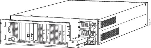
Figure 7-1 shows the front view of the PIX 535.
Figure 7-1 PIX 535 Front Panel
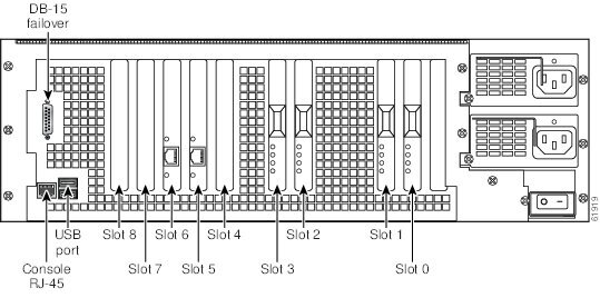
Figure 7-2 shows the rear view of the PIX 535.
Figure 7-2 PIX 535 Rear Panel
The PIX 535 has a fixed RJ-45 Console connector and a DB-15 Failover cable connector the USB port is not used at the present time.
Figure 7-3 shows the PIX 535 front panel LEDs.
Figure 7-3 PIX 535 Front Panel LEDs
.
Table 7-1 lists the states of the PIX 535 front panel LEDs.
Figure 7-4 shows the PIX 535 rear panel LEDs.
Figure 7-4 PIX 535 Rear Panel LEDs
Table 7-2 lists the states of the PIX 535 LEDs.
PIX 535 Network Interface Description
There are three separate buses for the nine interface slots in the PIX 535. The interfaces are counted from right to left on the PIX 535.
The slots and buses are configured as follows:
•
•
•
For optimum performance and throughput for the interface circuit boards, use the following guidelines:
•
•
•
•
•
•
Note
•
•
•
•
Table 7-3 lists the relative throughput of the Gigabit Ethernet combinations.
Installing the PIX 535
This section includes the following topics:
•
•
Before Installing the PIX 535
Observe the following before installing the PIX security appliance:
•
•
Mounting the PIX 535
To mount the PIX 535 on a rack, perform the following steps:
Step 1
Step 2
Step 3
PIX 535 Network Interface Installation
Note
To connect interfaces to the PIX 535, perform the following steps:
Step 1
Note
Step 2
Step 3
Note
Caution
Step 4
PIX 535 Feature Licenses
If you have the PIX-535-UR unrestricted feature license, the following options are available:
•
•
http://cisco.com/en/US/products/sw/secursw/ps2120/prod_command_reference_list.html
•
•
For information on upgrading feature licenses or downloading the latest software versions, refer to the configuration guide online at:
http://www.cisco.com/en/US/docs/security/asa/asa72/configuration/guide/conf_gd.html.
This section includes the following topics:
VPN Accelerator Card
The VPN Accelerator Card (VAC) for the Cisco PIX security appliance series is a card that provides high-performance, tunneling and encryption services suitable for site-to-site and remote access applications. The VAC is integrated with PIX 535 unrestricted (UR) and failover (FO) bundles. You can also purchase the VAC as a spare for use with PIX 535 units that have a restricted (R) license.
Note
VPN Accelerator Card+
The VAC+ is a 64-bit/66 MHz PCI card that provides faster tunneling and encryption services for Virtual Private Network (VPN) remote access, and site-to-site intranet and extranet applications, than the VAC. Each VAC+ occupies a single PCI slot in the system. The VAC+ is supported on any chassis that runs Version 6.3 software, has an appropriate license to run VPN software, and at least one PCI slot available. While the VAC continues to be supported in Version 6.3, if both types of cards, the VAC and the VAC+, are installed in a system running Version 6.3, the VAC card is ignored. The VAC+ runs at both 32-bit/33MHz and 64-bit/66 MHz, and does not slow down the bus when other 66 MHz cards are installed. We strongly recommend that you install the VAC+ in a 64bit/66 MHz slot. Performance is degraded if this recommendation is not followed.
The VAC+ driver supports the following:
•
•
•
•
•
Installing Failover
To set up a failover connection, perform the following steps:
Step 1
Note
Step 2
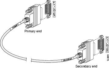
Install the cable for the PIX 535 as shown in Figure 7-5.
Figure 7-5 PIX 535 Failover Cable Connection
Step 3
Step 4
Step 5
Step 6
•
•
•
Note
Caution
Step 7
If the primary unit fails, the secondary unit automatically becomes active.
Note
Installing LAN-Based Failover
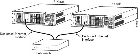
LAN-based failover supports failover between two units connected over a dedicated Ethernet interface. You can connect the LAN-based failover link by using a dedicated switch with no hosts or routers on the link or by using a crossover Ethernet cable to link the units directly.
Note
To set up a LAN-based failover connection, perform the following steps:
Step 1
Step 2
http://www.cisco.com/en/US/docs/security/asa/asa72/configuration/guide/conf_gd.html
Step 3
Step 4
Note
Figure 7-6 LAN-Based Failover Connections
Step 5
•
•
Note
Caution
Step 6
If the primary unit fails, the secondary unit automatically becomes active.
Replacing a Lithium Battery
The PIX security appliance has a lithium battery on its main circuit board. This battery has an operating life of about ten years. When the battery loses its charge, the PIX security appliance cannot function. The lithium battery is not a field-replaceable unit (FRU). Contact Cisco TAC to replace the battery.
Note
Warning
Installing a Memory Upgrade
The following statement applies to DC models only:
Warning
The following statement applies to both AC and DC models:
Warning
Caution
To install additional system memory, perform the following steps:
Step 1
Step 2
Step 3
Step 4
Step 5
Step 6
Step 7
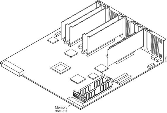
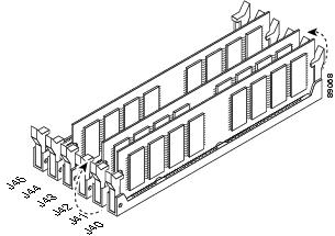
Populate memory Bank 0 first, then Bank 1. Memory sockets J40 and J43 comprise Bank 0; J41 and J44 comprise Bank 1. The PIX security appliance comes with 512 MB of RAM installed by default, so Bank 0 (J40 and J43) should be populated already. Install the additional 512 MB of RAM in Bank 1 (J41 and J44).
The memory DIMM pair that comprises a memory bank must be identical. Make sure that memory from the same vendor is placed together in the each memory bank (J40 and J43 in Bank 0 or J41 and J44 in Bank 1).
Figure 7-7 System Memory Location on the PIX 535 Component Tray
Step 8
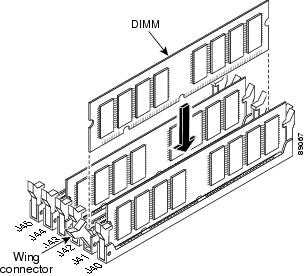
a.
b.
Figure 7-8 Inserting a DIMM Memory Strip in the PIX 535
Figure 7-9 Securing a DIMM Memory Strip in the PIX 535
Step 9
Step 10
Step 11
Step 12
Step 13
Note
Installing a Circuit Board in the PIX 535
The 4-port 64 bit/66 MHz FE card (PIX-4FE-66) is supported in software Versions 6.3, 6.2(2), 6.1(4), and 5.2(9), and later versions. These are the minimum software versions that support the card.
Note
The new card has the following characteristics:
•
•
•
•
This section includes the following topics:
•
•
•
•
PIX 535 Circuit Board Options
Table 7-4 lists the optional circuit board combinations that are available for the PIX 535. A maximum of eight interfaces are available with a restricted license, and 14 interfaces are available with an unrestricted license.
Note
Circuit Board Slot Description
There are nine circuit board slots (see Figure 7-10) using three separate buses for the PIX 535.
Figure 7-10 PIX 535 Back Panel Detail
The slots and buses are configured as follows:
•
•
•
For optimum performance and throughput for the interface circuit boards, you must use the following guidelines:
•
•
•
64-bit/66 MHz). Up to eight single-port FE circuit boards or up to two four-port FE circuit boards can be installed.–
Note
•
64-bit/66 MHz bus (Bus 0 or Bus 1). The overall speed of the bus will be reduced by the lower speed circuit board.•
Installing a Circuit Board
Note
To install a circuit board in the PIX 535, perform the following steps:
Step 1
Figure 7-11 The Component Tray at the Back of the PIX 535
Step 2
Step 3
Step 4
Step 5
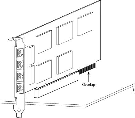
Step 6
Figure 7-12 4-Port Circuit Board Overlap
Note
16 MB Flash Circuit Board
Along with upgrading your Flash memory to 16 MB, the PIX security appliance 16 MB Flash circuit board includes pre-installed PIX security appliance software and a UR (unrestricted) 56-bit DES encryption license. The 16 MB Flash circuit board installs into the PIX security appliance ISA slot.
An illustration of the 16 MB Flash circuit board is shown in Figure 7-13.
Figure 7-13 16 MB Flash Circuit Board
You must observe the following when installing a 16 MB Flash circuit board:
•
•
•
•
To install the 16 MB Flash circuit board, perform the following steps:
Step 1
Step 2
After installation, the serial number of the PIX security appliance becomes the serial number supplied with the 16 MB Flash circuit board.
Step 3
Step 4
Step 5
Step 6
Step 7
VPN Accelerator Circuit Board
The VPN Accelerator (PIX-VPN-ACCEL) is an encryption and accelerator circuit board. The VPN Accelerator uses a PCI interface and therefore can only be installed in PIX security appliance platforms with PCI slots. The VPN Accelerator begins to function immediately after installation without the need of special installation configurations.
Note
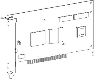
An illustration of the VPN Accelerator is shown in Figure 7-14.
Figure 7-14 PIX Security Appliance VPN Accelerator Circuit Board
Gigabit Ethernet Circuit Board
PIX security appliance supports 1000 Mbps (Gigabit) Ethernet. The Gigabit Ethernet circuit board has only one hardware speed and supports the following duplex options:
•
•
•
Note
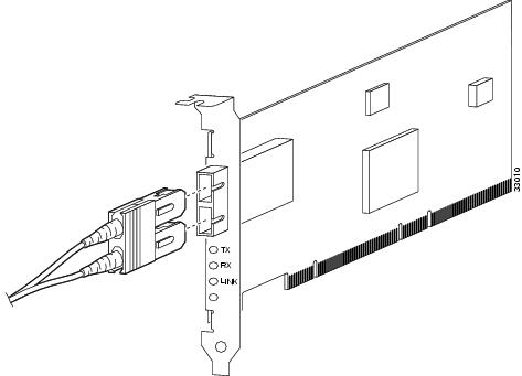
The Gigabit Ethernet circuit board and the fiber optic cable connection are shown in Figure 7-15.
Figure 7-15 Gigabit Ethernet Circuit Board
The Gigabit Ethernet circuit board has three LEDs:
•
•
•
Installing the PIX 535 DC Model
Warning
To install the PIX 535 DC power model, perform the following steps:
Step 1
Step 2
Step 3
Step 4
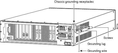
Step 5
Figure 7-16 Attaching a Grounding Lug to the PIX 535 DC
Step 6
Step 7
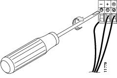
Step 8
Figure 7-17 Attaching DC Power Cables
Step 9
Step 10
Step 11
Note
Your unit is now ready to configure. Refer to the configuration guide online at:
http://www.cisco.com/en/US/docs/security/asa/asa72/configuration/guide/conf_gd.html.