Cisco PIX Security Appliance Hardware Installation Guide, Version 7.2
PIX 501

Table Of Contents

PIX 501

PIX 501 Product Overview

Installing the PIX 501

Connecting a Power Supply Module to the PIX 501

PIX 501 Cable Lock

Removing and Replacing the PIX 501 Chassis Cover

Removing the Chassis Cover

Replacing the Chassis Cover

Replacing a Lithium Battery


PIX 501


This chapter describes how to install the PIX 501, and includes the following sections:

PIX 501 Product Overview

Installing the PIX 501

Connecting a Power Supply Module to the PIX 501

Removing and Replacing the PIX 501 Chassis Cover

Replacing a Lithium Battery


Note The PIX 501 is not supported in software Version 7.0(1).


PIX 501 Product Overview

This section describes the PIX 501 front and rear panels and the panel LEDs.

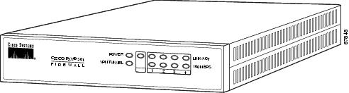
Figure 2-1 shows the front view of the PIX 501.

Figure 2-1 PIX 501 Front Panel

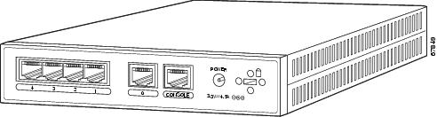
Figure 2-2 shows the rear view of the PIX 501.

Figure 2-2 PIX 501 Rear Panel

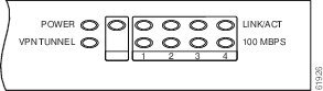
Figure 2-3 shows the PIX 501 front panel LEDs.

Figure 2-3 PIX 501 Front Panel LEDs

Table 2-1 lists the states of the PIX 501 front panel LEDs.

Table 2-1 PIX 501 Front Panel LEDs 

LED
Color
State
Description

POWER

Green

On

The device is powered on.


Off

The device is powered off.

LINK/ACT

Green

Flashing

Network activity, such as Internet access, is present.


On

The correct cable is in use, and the connected equipment has power and is operational.


Off

No link is established.


Tip If the LINK/ACT LED does not light up, you might be using the wrong type of cable. Try replacing the yellow, straight-through Ethernet cable with the orange, crossover Ethernet cable.


VPN TUNNEL

Green

On

One or more IKE/IPSec VPN tunnels are established.


Off

One or more IKE/IPSec VPN tunnels are disabled. If the standard configuration is not modified to support VPN tunnels, the LED does not light up because it is disabled by default. Also, the LED does not light up when PPTP/L2TP tunnels are established.

100 MBPS

Green

On

The interface is enabled at 100 Mbps (autonegotiated).


Off

The interface is enabled at 10 Mbps.


Installing the PIX 501

Place the PIX 501 on a flat, stable surface. The PIX 501 is not rack mountable.

To install the PIX 501, perform the following steps:


Step 1 Connect Port 0, the outside Ethernet port, to the public network.

Use the yellow Ethernet cable (72-1482-01) to connect the device to a switch or hub.

Use the orange Ethernet cable (72-3515-01) to connect the device to a DSL modem, cable modem, or router.

Step 2 Connect your PC or the other network devices to one of the four switched inside ports (numbered 1 through 4).


Connecting a Power Supply Module to the PIX 501

This section describes how to connect the power supply module to a PIX 501. Use this information in conjunction with the Regulatory Compliance and Safety Information document.

To connect the power supply module to the PIX 501, perform the following steps:


Step 1 Connect the small, round connector of the power supply cable to the power connector on the rear panel (see Figure 2-4).

Step 2 Connect the AC power connector of the power supply input cable to an electrical outlet.


Note The PIX 501 does not have a power switch. Completing Step 2 powers on the device.


Figure 2-4 Connecting the Power Supply Module to the PIX 501


PIX 501 Cable Lock

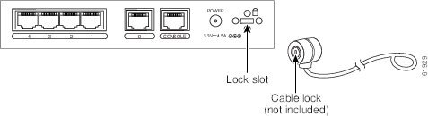
The PIX 501 includes a slot that accepts standard desktop cable locks to provide physical security for small portable equipment, such as laptop computers (see Figure 2-5).

Figure 2-5 PIX 501 Security Cable Lock

To install a security cable lock, perform the following steps:


Step 1 Attach the cable lock to the lock slot on the back panel of the PIX 501.

Step 2 Follow the directions from the manufacturer for attaching the other end of the device for securing the PIX 501.


Removing and Replacing the PIX 501 Chassis Cover

This section describes how to remove and replace the chassis cover from the PIX 501. This section includes the following topics:

Removing the Chassis Cover

Replacing the Chassis Cover

Removing the Chassis Cover

To remove the chassis cover, perform the following steps:


Note Removing the chassis cover does not affect your Cisco warranty. Upgrading the PIX security appliance does not require any special tools and does not create any radio frequency leaks.


Step 1 Read the Regulatory Compliance and Safety Information document.

Step 2 Unplug the power cord from the power outlet to power off the security appliance.

Step 3 Disconnect the network interface cables.

Step 4 Turn the unit upside down so that the top of the chassis is resting on a flat surface, and the front of the chassis is facing toward you.

Step 5 Unscrew the single screw located on the bottom of the chassis, centered under the front panel (see Figure 2-6).

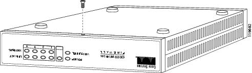
Figure 2-6 Removing PIX 501 Bottom Panel Screw

Step 6 Return the chassis to the upright position. Note that the chassis is comprised of two sections: top and bottom (see Figure 2-7).

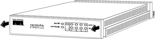
Figure 2-7 Sliding the Chassis Cover Off the Chassis

Step 7 With the front panel facing you, slide the top section toward you, and then lift it up and off the bottom section (see Figure 2-7).


Replacing the Chassis Cover


Caution Do not operate PIX security appliances without the chassis cover installed. The chassis cover protects the internal components, prevents electrical shorts, and provides proper air-flow for cooling the electronic components.

To replace the chassis cover, perform the following steps:


Step 1 Place the chassis on a secure surface with the front panel facing you.

Step 2 Hold the chassis cover so the tabs at the rear of the chassis cover are aligned with the chassis bottom.

Step 3 Lower the front of the cover onto the chassis, making sure that the side tabs of the cover fit under the side panels of the chassis.

Step 4 Slide the chassis cover toward the front, making sure that the cover tabs fit under the back panel, and the back panel tabs fit under the chassis cover.

Step 5 Secure the chassis cover with the screw you set aside earlier.

Step 6 Reconnect the network interface cables.

Step 7 Place the PIX 501 on a flat, stable surface. The PIX 501 is not rack mountable.

Step 8 Reconnect the power cord to the power outlet to power on the security appliance.


Replacing a Lithium Battery

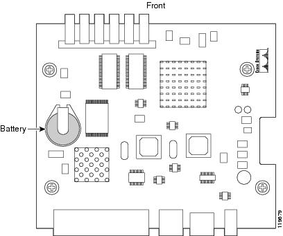
The PIX 501 has a lithium battery on the main circuit board (see Figure 2-8). This battery has an operating life of about ten years. When the battery loses its charge, the PIX security appliance cannot function. The lithium battery is a field-replaceable unit (FRU). You can use a standard 3V lithium battery to replace the used battery.

Figure 2-8 PIX 501 Lithium Battery Location


Warning Danger of explosion exists if the lithium battery is incorrectly replaced. Replace only with the same or equivalent type recommended by the manufacturer. Dispose of used batteries according to the manufacturer's instructions.


To replace the lithium battery, perform the following steps:


Step 1 Remove the chassis cover as described in the "Removing the Chassis Cover" section.

Step 2 Use a flathead screwdriver to slide the battery out of the metal clip on the circuit board (see Figure 2-8).

Step 3 Place the used battery aside and replace it with a new battery. Install the new battery writing side up.

Step 4 The battery snaps into place as you slide it into the battery slot.

Step 5 Replace the chassis cover as described in the "Replacing the Chassis Cover" section.