Feedback
Table Of Contents
Connecting a Power Supply Module to the PIX 506/506E
Removing and Replacing the PIX 506/506E Chassis Cover
PIX 506/506E
This chapter describes how to install a PIX 506/506E, and includes the following sections:
•
PIX 506/506E Product Overview
•
•
Note
The PIX 506 and the PIX 506E are not supported in software Version 7.0(1).
PIX 506/506E Product Overview
This section describes the PIX 506/506E front and rear panels and the panel LEDs.
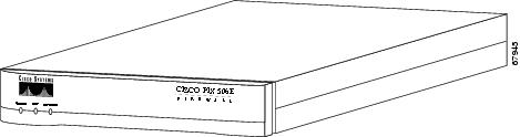
Figure 3-1 shows the front view of the PIX 506/506E.
Figure 3-1 PIX 506/506E Front Panel
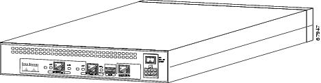
Figure 3-2 shows the rear view of the PIX 506/506E.
Figure 3-2 PIX 506/506E Rear Panel
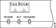
Figure 3-3 shows the PIX 506/506E front panel LEDs.
Figure 3-3 PIX 506/506E Front Panel LEDs
Table 3-1 lists the states of the PIX 506/506E front panel LEDs.
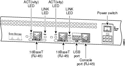
Figure 3-4 shows the PIX 506/506E rear panel LEDs.
Figure 3-4 PIX 506/506E Rear Panel LEDs
Table 3-2 lists the states of the PIX 506/506E rear panel LEDs.
Table 3-2 PIX 506/506E Rear Panel LEDs
ACT
Green
On
Shows network activity.
LINK
Green
On
Shows that data is passing on the network to which the connector is attached.
The USB port at the left of the Console port is not used.
Installing the PIX 506/506E
Place the PIX 506/506E on a flat, stable surface. The PIX 506/506E is not rack mountable.
To install the PIX 506/506E, perform the following steps:
Step 1
Note
Step 2
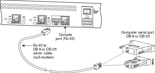
Figure 3-5 PIX 506/506E Serial Console Cable
Step 3
Note
Step 4
Connecting a Power Supply Module to the PIX 506/506E
This section describes how to connect the power supply module to the PIX 506/506E. Use this information in conjunction with the Regulatory Compliance and Safety Information document.
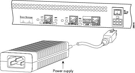
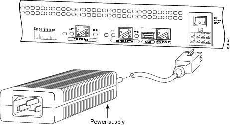
The PIX 506/506E uses an external AC to DC power supply. Power is supplied to the PIX 506/506E by connecting the power supply to the back of the security appliance and connecting a separate AC power cord to the power supply.
Figure 3-6 displays the cable connection from the power supply to the PIX 506, and displays the AC power cord connector (at the opposite end of the power supply).
Figure 3-6 Connecting the Power Supply Module to the PIX 506 6-Pin Connector
Figure 3-7 displays the cable connection from the power supply to the PIX 506E, and displays the AC power cord connector (at the opposite end of the power supply).
Figure 3-7 Connecting the Power Supply Module to the PIX 506E 8-Pin Connector
To connect the power supply module, perform the following steps:
Step 1
Step 2
Step 3
Removing and Replacing the PIX 506/506E Chassis Cover
This section describes how to remove and replace the chassis cover from the PIX 506/506E. This section includes the following topics:
Removing the Chassis Cover
To remove the chassis cover, perform the following steps:
Note
Step 1
Step 2
Warning
Step 3
Step 4
Figure 3-8 Removing PIX 506/506E Chassis Cover Screws
Step 5
Replacing the Chassis Cover
Caution
To replace the chassis cover, perform the following steps:
Step 1
Step 2
Step 3
Step 4
Step 5
Step 6
Step 7
Step 8
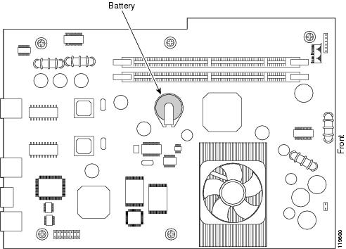
Replacing a Lithium Battery
The PIX 506/506E has a lithium battery on its main circuit board (see Figure 3-9). This battery has an operating life of about ten years. When the battery loses its charge, the PIX security appliance cannot function. The battery is a field-replaceable unit (FRU). You can use a standard 3V lithium battery to replace the used battery.
Figure 3-9 PIX 506/506E Lithium Battery Location
Warning
To replace the lithium battery, perform the following steps:
Step 1
Step 2
Step 3
Step 4
Step 5
Step 6