Table Of Contents
Configuration Examples
Two Interfaces without NAT - Basic
Two Interfaces with NAT - Basic
Two Interfaces with NAT - Advanced
Three Interfaces without NAT
Three Interfaces with NAT
Four Interfaces with NAT
Guidelines for a Configuration with Four Interfaces
Higher Security Level to Lower Security Level Access
Lower Security Level to Higher Security Level Access
IP Addresses for a Configuration with Four Interfaces
Configuration with Four Interfaces
Six Interfaces with NAT
Guidelines for a Configuration with Six Interfaces
Guidelines
Higher Security Level to Lower Security Level Access
Lower Security Level to Higher Security Level Access
IP Addresses for a Configuration with Six Interfaces
Configuration for Six Interfaces
IPSec with Manual Keys
PIX Firewall 1 Configuration
PIX Firewall 2 Configuration
VPN Tunnel Using Pre-shared Keys without NAT
Configuring PIX Firewall 1 for VPN Tunneling
Configuring PIX Firewall 2 for VPN Tunneling
VPN Tunnel Using VeriSign Digital Certificates
Configuring PIX Firewall 1 for a VeriSign Certificate
Configuring PIX Firewall 2 for a VeriSign Certificate
VPN Tunnel Using Entrust Digital Certificates
Configuring PIX Firewall 1 for an Entrust Certificate
Configuring PIX Firewall 2 for an Entrust Certificate
VPN Client Access with Manual IP Address and Pre-shared Keys
Configuring the PIX Firewall for Pre-shared Keys
Configuring the Cisco Secure VPN Client
VPN Client Access with AAA and Pre-shared Keys
Configuring the PIX Firewall
Configuring the Cisco Secure VPN Client
Working with IPSec and NAT on the PIX Firewall
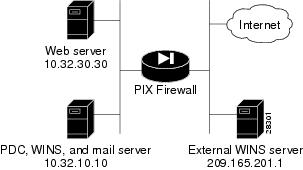
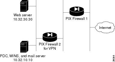
One PIX Firewall and One External WINS Server
PIX Firewall Configuration
Usage Notes
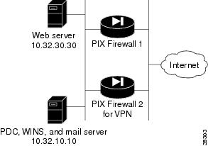
Parallel PIX Firewall Units without an Internal Router
PIX Firewall Unit 1 Configuration
PIX Firewall Unit 2 for VPN Configuration
Usage Notes
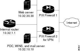
Parallel PIX Firewall Units with an Internal Router
Usage Notes
Serial PIX Firewall Units
PIX Firewall Unit 1 Configuration
PIX Firewall Unit 2 for VPN Configuration
Usage Note
Configuration Examples
Before using this chapter, be sure that you have planned your site's security policy, as described in "," and configured the PIX Firewall, as described in "." Acronyms in the text are defined in "."
This chapter provides network diagrams and the configuration instructions to create them. Further information about the commands in the configurations can be found in "."
If you are starting a configuration, you may want to use the forms provided in "," to help you plan a configuration.
This chapter includes the following sections:
• Two Interfaces without NAT - Basic
•Two Interfaces with NAT - Basic
•Two Interfaces with NAT - Advanced
•Three Interfaces without NAT
•Three Interfaces with NAT
•Four Interfaces with NAT
•Six Interfaces with NAT
•IPSec with Manual Keys
•VPN Tunnel Using Pre-shared Keys without NAT
•VPN Tunnel Using VeriSign Digital Certificates
•VPN Tunnel Using Entrust Digital Certificates
•VPN Client Access with Manual IP Address and Pre-shared Keys
•VPN Client Access with AAA and Pre-shared Keys
•Working with IPSec and NAT on the PIX Firewall
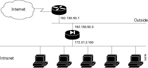
Two Interfaces without NAT - Basic
When you first add a PIX Firewall to an existing network, it is easiest to implement its use if you do not have to renumber all the inside and outside IP addresses. The configuration in illustrates this scenario. Syslog is enabled to facilitate troubleshooting. All inside hosts can start connections. All external hosts are blocked from initiating connections or sessions on inside hosts. If you use Inter-NIC registered IP addresses, only use those addresses that you own.
Figure 5-1 Two Interfaces without NAT
lists the configuration.
Table 5-1 Two Interfaces without NAT
Configuration
|
Description
|
nameif ethernet0 outside security0
nameif ethernet1 inside security100
|
PIX Firewall provides nameif and interface command statements for the interfaces in the default configuration.
|
ip address outside 192.150.50.3 255.255.255.0
ip address inside 172.31.2.100 255.255.255.0
|
Identify the IP addresses for both interfaces.
|
|
Specifies the host name for the PIX Firewall. This name appears in the command line prompt.
|
|
Sets the ARP timeout to 14,400 seconds (four hours). Entries are kept in the ARP table for four hours before they are flushed. Four hours is the standard default value for ARP timeouts.
|
|
Disables failover access.
|
|
Enables use of text strings instead of IP addresses. This makes your configuration files more readable.
|
|
Enables paging so that if when 24 lines of information display, PIX Firewall pauses the listing and prompts you to continue.
|
logging buffered debugging
|
Enables syslog messages, which provide diagnostic information and status for the PIX Firewall. PIX Firewall makes it easy to view syslog messages with the show logging command.
|
nat (inside) 0 172.31.2.0 255.255.255.0
|
Lets inside IP addresses be recognized on the outside network and lets inside users start outbound connections.
|
|
Sets RIP listening attributes. The first command causes the PIX Firewall to broadcast a default route on the inside interface. Broadcasting a default route sends network traffic to the PIX Firewall if your internal network is running RIP. The next command disables passive RIP listening on the inside. The next command disables broadcasting a default route on the outside. This is desirable when the network is attached to the Internet, but not when on an intranet. The last command disables passive RIP listening on the outside.
|
route outside 0.0.0.0 0.0.0.0 192.150.50.1 1
|
Sets the outside default route to the router attached to the Internet.
|
timeout xlate 3:00:00 conn 1:00:00
half-closed 0:10:00 udp 0:02:00
timeout rpc 0:10:00 h323 0:05:00
timeout uauth 0:05:00 absolute
|
Default values for the maximum duration that PIX Firewall resources can remain idle until being freed. Additional users cannot make connections until a connection resource is freed either by a user dropping a connection or by an xlate and conn timer time out.
|
snmp-server community public
|
Specifies that SNMP information may be accessed by internal hosts that know the community string, but PIX Firewall does not send trap information to any host.
|
|
Sets the maximum transmission unit value for Ethernet access.
|
Two Interfaces with NAT - Basic
In , the PIX Firewall has two interfaces. In this configuration, there is no user authentication, no authorization, and no syslog or SNMP logging of troubleshooting messages. All inside users can start outbound connections and all connections from the outside are dropped. A configuration such as this is a good example of the basic commands used to create a secured network.
Figure 5-2
Two Interfaces with NAT
lists the configuration.
Table 5-2 Two Interfaces with NAT
Configuration
|
Description
|
nameif ethernet0 outside security0
nameif ethernet1 inside security100
|
PIX Firewall provides nameif and interface command statements for the interfaces in the default configuration.
|
ip address outside 192.150.50.3 255.255.255.0
ip address inside 10.0.0.3 255.0.0.0
|
Identify the IP addresses for both interfaces.
|
|
Set the ARP timeout to 14,400 seconds (four hours). Entries are kept in the ARP table for four hours before they are flushed.
|
|
Permit all inside users to start outbound connections using the translated IP addresses from the global pool.
|
global (outside) 1 192.150.50.76-192.150.50.85
global (outside) 1 192.150.50.75
|
Create a pool of global addresses that translated addresses use when they exit the firewall from the protected networks to the unprotected networks. The global command statement is associated with a nat command statement by the nat_ID, which in this example is 1. Because there are only 9 IP addresses in the pool, a PAT (Port Address Translation) global is added to handle overflow.
|
|
PIX Firewall does use RIP information for its forwarding decisions, but these commands can be useful for broadcasting a default route—if your network uses the RIP protocol. However, most do not. In most cases, you can ignore these command statements.
|
route outside 0.0.0.0 0.0.0.0 192.150.50.1 1
|
Set the outside default route to the router attached to the Internet.
|
timeout xlate 3:00:00 conn 1:00:00
half-closed 0:10:00 udp 0:02:00
timeout rpc 0:10:00 h323 0:05:00
timeout uauth 0:05:00 absolute
|
Default values for the maximum duration that PIX Firewall resources can remain idle until being freed. Additional users cannot make connections until a connection resource is freed either by a user dropping a connection or by an xlate and conn timer time out.
|
conduit permit icmp any any
|
Allows inbound and outbound pings.
|
snmp-server community public
|
Specifies that SNMP information may be accessed by internal hosts that know the community string, but PIX Firewall does not send trap information to any host.
|
telnet 10.0.0.100 255.255.255.255
|
Specifies that host 10.0.0.100 is permitted to access the PIX Firewall console via Telnet and that 15 minutes are allowed before the idle timer runs out and the session is logged off.
|
|
Sets the maximum transmission unit value for Ethernet access.
|
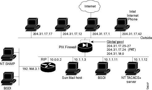
Two Interfaces with NAT - Advanced
The configuration in provides an overview of how the various commands are used to create a configuration.
This configuration shows the use of PAT (Port Address Translation), denying Java applets, using the AAA commands, creating a mail server, permitting NFS, initializing SNMP, and setting console access with Telnet.
Figure 5-3 Two Interfaces with NAT - Advanced
lists the configuration.
Table 5-3 Two Interfaces with NAT - Advanced
Configuration
|
Description
|
nameif ethernet0 outside security0
nameif ethernet1 inside security100
|
PIX Firewall provides nameif and interface command statements for the interfaces in the default configuration.
|
ip address inside 10.1.1.1 255.255.255.0
ip address outside 204.31.17.10 255.255.255.0
|
Identify the IP addresses for both interfaces.
|
|
The logging host command statement specifies which host runs a syslog server. This command also causes the PIX Firewall to start sending syslog messages to that host. The logging trap command statement sets syslog to send all possible messages to the syslog host. The no logging console command statement disables displaying messages to the console.
|
|
Set an ARP timeout to 600 seconds (10 minutes). Use this arp timeout command statement when you set up a network and change inside and outside host addresses often.
|
nat (inside) 1 0.0.0.0 0.0.0.0
nat (inside) 2 192.168.3.0 255.255.255.0
|
Permit all inside users to start outbound connections using the translated IP addresses from the global pool.
|
global (outside) 1 204.31.17.25-204.31.17.27
global (outside) 1 204.31.17.24
global (outside) 2 192.159.1.1-192.159.1.254
|
Create two pools of global addresses to let the nat command statements use the address pools for translating internal IP addresses to external addresses. Each pool is designated by the number from the nat command statement, in this case, 1 and 2.
|
conduit permit icmp any any
|
Allow inbound and outbound pings.
|
outbound 10 deny 192.168.3.3 255.255.255.255 1720
outbound 10 permit 192.168.3.3 255.255.255.255 80
outbound 10 deny 192.168.3.3 255.255.255.255 java
outbound 10 permit 10.1.1.11 255.255.255.255 80
|
Create access lists to determine which hosts can access services. The first outbound command statement denies host 192.168.3.3 from accessing H.323 (port 1720) services such as MS NetMeeting or InternetPhone. The next command statement denies all hosts from accessing the Web (port 80). The next two command statements permits host 192.168.3.3 to use the Web, but denies its users from downloading Java applets. The last outbound command statement permits host 10.1.1.11 access to the Web (at port 80) and to download Java applets. This permit command statement outweighs the previous deny regardless of the order in which the command statements are entered into the configuration.
|
apply (inside) 10 outgoing_src
|
Specify that the outbound group regulates the activities of inside hosts starting outbound connections.
|
|
|
The first command disables RIP listening on the outside interface. The second command disables broadcasting a default route on the outside.
The third command enables RIP listening on the inside and the last command causes PIX Firewall to broadcast a default route on the inside interface.
|
route outside 0 0 204.31.17.1 1
|
Set the default route on the outside network to be 204.31.17.1. This is the IP address of the host connecting to the Internet.
|
aaa-server TACACS+ (inside) host 10.1.1.12 1q2w3e
aaa authentication any inside 192.168.3.0
255.255.255.0 0 0 TACACS+
aaa authorization any inside 192.168.3.0
|
The aaa-server command specifies the IP address of the TACACS+ authentication server. The aaa authentication command statement specifies that users on network 192.168.3.0 starting FTP, HTTP, and Web connections from the inside interface be prompted for their usernames and passwords before being permitted to access these servers on other interfaces. The aaa authorization command statement lets the users on 192.168.3.0 access FTP, HTTP, or Telnet, and any TCP connections to anywhere as authorized by the AAA server. Even though it appears that the aaa commands let the PIX Firewall set security policy, the authentication server actually does the work to decide which users are authenticated and what services they can access when authentication is permitted.
|
static (inside, outside) 204.31.19.0 192.168.3.0
netmask 255.255.255.0
conduit permit tcp 204.31.19.0 255.255.255.0

eq h323 any
|
The static command statement creates a net static command statement, which is a static command statement for a Class IP address, in this case for IP addresses 204.31.19.1 through 204.31.19.254. The static command shows the use of the connection limit and the embryonic limit arguments. The maximum number of connections limits the number of connections a host can use. This command permits access to only 10 users and up to 30 SYNs (embryonic connections). Note that the static command's maximum connections option applies to both inbound and outbound connections.
The conduit command statement lets users on the Internet send InternetPhone (port h323) requests to users on 192.168.3.x while addressing them as 204.31.19.x.
|
static (inside, outside) 204.31.17.29 10.1.1.11
conduit permit tcp host 204.31.17.29 eq 80 any
|
The static command statement with the conduit command statement establishes an externally visible IP address for Web access (port 80 in the conduit command statement).
|
conduit permit udp host 204.31.17.29 eq rpc

host 204.31.17.17
|
Refine the accessibility of the static command by permitting Sun RPC over the UDP portmapper on port 111. Refer to the UNIX /etc/rpc file and the UNIX rpc(3N) command page for more information. Once you create a conduit for RPC, you can use the following command from outside host 204.31.17.17 to track down the activity of a PCNFSD on RPC 150001:
rpcinfo -u 204.31.17.29 150001
Another use of RPC is with the following command to see the exports of 204.31.17.29 if you want to allow NFS mounting from outside in:
showmount -e 204.31.17.29
Many protocols based on RPC, as well as NFS, are insecure and should be used with caution. Review your security policies carefully before permitting access to RPC.
|
conduit permit udp host 204.31.17.29 eq 2049

host 204.31.17.17
|
Permit NFS access, which occurs at port 2049 and provides access between the outside and inside, such that 204.31.17.17 can mount 10.1.1.11.
|
static (inside, outside) 204.31.17.30 10.1.1.3

netmask 255.255.255.255 10 10
conduit permit tcp host 204.31.17.30 eq smtp any
|
Identify access to the 10.1.1.3 mail server through global address 204.31.17.30. The conduit permits any outside host access to the static via SMTP (port 25). By default, PIX Firewall restricts all access to mail servers to RFC 821 section 4.5.1 commands of DATA, HELO, MAIL, NOOP, QUIT, RCPT, and RSET. This occurs via the Mail Guard service which is set with the following default configuration command:
fixup protocol smtp 25
Another aspect of providing access to a mail server is setting being sure that you have a DNS MX record for the static's global address, which outside users access when sending mail to your site.
|
conduit permit tcp host 204.31.17.30 eq 113 any
|
Create access to port 113, the IDENT protocol. If the mail server has to talk to many mail servers on the outside which connect back with the now obsolete and highly criticized IDENT protocol, use this conduit command statement to speed up mail transmission.
|
snmp-server host 192.168.3.2
snmp-server location building 42
snmp-server contact polly hedra
snmp-server community ohwhatakeyisthee
|
These commands specify that host 192.168.3.2 can receive SNMP events, which the PIX Firewall sends via syslog. The location and contact commands identify where the host is and who administers it. The community command describes the password in use at the SNMP server for verifying network access with the server.
|
telnet 10.1.1.11 255.255.255.255
telnet 192.168.3.0 255.255.255.0
|
These commands permit host access to the PIX Firewall console. The first telnet command permits a single host, 10.1.1.11 to access the PIX Firewall console with Telnet. The 255 value in the last octet of the netmask means that only the specified host can access the console.
The second telnet command permits PIX Firewall console access from all hosts on the 192.168.3.0 network. The 0 value in the last octet of the netmask permits all hosts in that network access. However, Telnet only permits 16 hosts simultaneous access to the PIX Firewall console over Telnet.
|
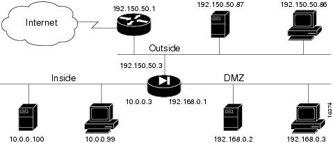
Three Interfaces without NAT
In , the PIX Firewall has three interfaces. No address translation is performed between the interfaces.
Figure 5-4
Three-interface Configuration
The network has the following IP addresses and network masks:
•Outside network interface address: 192.150.50.50, network mask: 255.255.255.240
•Inside network interface address: 192.150.50.98, network mask: 255.255.255.240
•DMZ network interface address: 192.150.50.68, network mask: 255.255.255.240
lists the configuration.
Table 5-4 Three-interface without NAT Configuration
Configuration
|
Description
|
nameif ethernet0 outside security0
nameif ethernet1 inside security100
nameif ethernet2 dmz security50
|
PIX Firewall provides nameif and interface command statements for the interfaces in the default configuration.
|
ip address outside 192.150.50.50 255.255.255.240
ip address inside 192.150.50.98 255.255.255.240
ip address dmz 192.150.50.68 255.255.255.240
|
Identify the IP addresses for each of the three interfaces.
|
|
Specifies the host name for the PIX Firewall. This name appears in the command line prompt.
|
|
Sets the ARP timeout to 14,400 seconds (four hours). Entries are kept in the ARP table for four hours before they are flushed. Four hours is the standard default value for ARP timeouts.
|
|
Disables failover access.
|
|
Lets you use text strings instead of IP addresses, which makes your configuration easier to read.
|
|
Enables paging so that if when 24 lines of information display, PIX Firewall pauses the listing and prompts you to continue.
|
logging buffered debugging
|
Enable syslog messages, which provide diagnostic information and status for the PIX Firewall. You can view the messages with the show logging command and clear the message buffer with the clear logging command.
|
|
Sets RIP listening attributes. The first two command statements enable RIP listening on the inside, but disable it on the outside. The no rip interface default commands causes PIX Firewall to not broadcast a default route on either interface.
|
route outside 0.0.0.0 0.0.0.0 192.150.50.1 1
|
Sets the outside default route to the router attached to the Internet.
|
timeout xlate 3:00:00 conn 1:00:00
half-closed 0:10:00 udp 0:02:00
timeout rpc 0:10:00 h323 0:05:00
timeout uauth 0:05:00 absolute
|
Default values for the maximum duration that PIX Firewall resources can remain idle until being freed.
|
snmp-server community public
|
Specifies that SNMP information may be accessed by internal hosts that know the community string, but PIX Firewall does not send trap information to any host.
|
|
Sets the maximum transmission unit value for Ethernet access.
|
nat (inside) 0 192.150.50.96 255.255.255.240
|
Disables NAT (Network Address Translation).
|
static (dmz,outside) 192.150.50.70 192.150.50.70
conduit permit tcp host 192.150.50.70 any
|
Maps access to the 192.150.50.70 host on the dmz interface. The conduit command lets any outside user access the host on any port.
|
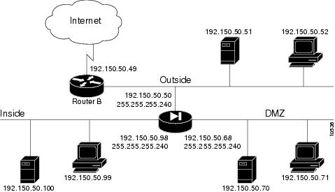
Three Interfaces with NAT
In , the PIX Firewall has three interfaces and these attributes:
•Address translation is performed between the interfaces.
•A web server on the DMZ interface is publicly accessible. The name command maps its host address to the name "webserver."
•The inside network has illegal addresses (10.0.0.0), the DMZ interface has RFC 1918 addresses (192.168.0.0), and the outside network has legal, registered addresses (192.150.50.0).
•TCP and UDP connections from the inside are allowed to go out on the DMZ and outside.
•An inside host has been given Telnet access to the PIX Firewall console.
Figure 5-5
Three Interfaces with NAT
The network has the following IP addresses and network masks:
•Outside network interface address: 192.150.50.3, network mask: 255.255.255.0
•Allowable global and static addresses on the outside network: 192.150.50.74-192.150.50.85
•Inside network interface address: 10.0.0.3, network mask: 255.0.0.0
•DMZ network interface address: 192.168.0.1, network mask: 255.255.255.0
Table 5-5 Three Interfaces with NAT Configuration
Configuration
|
Description
|
nameif ethernet0 outside security0
nameif ethernet1 inside security100
nameif ethernet2 dmz security50
|
PIX Firewall provides nameif and interface command statements for the interfaces in the default configuration.
|
ip address outside 192.150.50.3 255.255.255.0
ip address inside 10.0.0.3 255.0.0.0
ip address dmz 192.168.0.1 255.255.255.0
|
Identify the IP addresses for each of the three interfaces.
|
|
Specify the host name for the PIX Firewall. This name appears in the command line prompt.
|
|
Set the ARP timeout to 14,400 seconds (four hours). Entries are kept in the ARP table for four hours before they are flushed. Four hours is the standard default value for ARP timeouts.
|
|
Disable failover access.
|
|
Lets you use text strings instead of IP addresses, which makes your configuration easier to read.
|
|
Enable paging so that if after 24 lines of information display, PIX Firewall pauses the listing and prompts you to continue.
|
logging buffered debugging
|
Enable syslog messages, which provide diagnostic information and status for the PIX Firewall. You can view the messages with the show logging command and clear the message buffer with the clear logging command.
|
|
Disable RIP attributes.
|
route outside 0.0.0.0 0.0.0.0 192.150.50.1 1
|
Set the outside default route to the router attached to the Internet.
|
conduit permit icmp any any
|
Allow inbound and outbound pings.
|
timeout xlate 3:00:00 conn 1:00:00
half-closed 0:10:00 udp 0:02:00
timeout rpc 0:10:00 h323 0:05:00
timeout uauth 0:05:00 absolute
|
Default values for the maximum duration that PIX Firewall resources can remain idle until being freed.
|
snmp-server community public
|
Specify that SNMP information may be accessed by internal hosts that know the community string, but PIX Firewall does not send trap information to any host.
|
|
Set the maximum transmission unit value for Ethernet access.
|
telnet 10.0.0.100 255.255.255.255
|
Give Telnet access to PIX Firewall console to inside host. Use the timeout feature to set the maximum time a Telnet session can be idle before PIX Firewall closes the connection to 15 minutes. The default is 5 minutes.
|
global (outside) 1 192.150.50.75-192.150.50.85
global (outside) 1 192.150.50.74
global (dmz) 1 192.168.0.10-192.168.0.20
|
Create a pool of global addresses for the outside and DMZ interfaces. Because there are only 10 outside IP addresses, add a PAT global to handle overflow. The global (dmz) command gives inside users access to the web server on the DMZ interface.
|
nat (inside) 1 10.0.0.0 255.0.0.0
nat (dmz) 1 192.168.0.0 255.255.255.0
|
Let inside users start connections on the DMZ and outside interfaces, and let DMZ users start connections on the outside interface.
|
name 192.168.0.2 webserver
|
Give the IP address of the web server a label.
|
static (dmz,outside) 192.150.50.90 webserver
conduit permit tcp host 192.150.50.90 eq 80 any
|
Let any user on the outside interface access the web server on the DMZ interface.
|
lists the configuration.
Four Interfaces with NAT
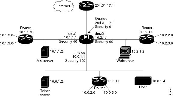
In , the PIX Firewall has four interfaces. In this configuration, there is no user authentication and no authorization. NAT (Network Address Translation) is in effect to translate addresses. In this example, users on all interfaces have access to all the servers and hosts on the inside, dmz1, and dmz2 interfaces can start connections.
This section includes the following topics:
•Guidelines for a Configuration with Four Interfaces
•IP Addresses for a Configuration with Four Interfaces
•Configuration with Four Interfaces
Figure 5-6
Four Interfaces with NAT
Configuring PIX Firewall for four interfaces requires more attention to detail than other configurations.
Guidelines for a Configuration with Four Interfaces
This section includes the following topics:
•Higher Security Level to Lower Security Level Access
•Lower Security Level to Higher Security Level Access
The most important guidelines to remember are:
•Higher to lower—To let users on a higher security level interface access hosts on a lower security interface, use the nat and global commands; for example, to let users on the inside interface access the web server on the dmz2 interface. As seen in , the inside interface has a security level of 100 and the dmz2 interface has a security level of 60.
The nat command lets users access all hosts on all lower security level interfaces. The global command identifies the interface through which the nat access is permitted.
•Lower to higher—To let users on a lower security level interface access hosts on a higher security interface, use the static and conduit commands; for example, to let users on the dmz1 interface access the Telnet server on the inside interface. As seen in , the dmz1 interface has a security level of 40 and the inside interface has a security level of 100.
The static command lets users access specifically identified hosts on a single interface. The conduit command identifies the port or ports through which access is permitted.
The sections that follow provide more information on these guidelines.
Higher Security Level to Lower Security Level Access
To let users on each higher security level interface access servers on each lower security level interface, follow these steps:
Step 1 Letting higher security level interface users access a lower security level interface has two components: you use the nat command to specify from where users start connections, and you use the global command to specify to where access is permitted. You associate the nat and global commands together with the NAT ID, which in this example configuration is 1. The nat command lets users start connections from the specified interface to all lower security interfaces, the global command permits access to translated connections from any higher security level interface.
To let users from the inside interface start connections, use:
Step 2 To let users on the dmz2 interface start connections, use:
Step 3 To let users on the dmz1 interface start connections, use:
Step 4 To permit access to the dmz2 interface for translated connections, use:
global (dmz2) 1 10.2.1.10-10.2.1.254
Step 5 To permit access to the dmz1 interface for translated connections, use:
global (dmz1) 1 10.1.1.10-10.1.1.254
Step 6 To permit access to the outside interface for translated connections, use:
global (outside) 1 204.31.17.10-204.31.17.254
Lower Security Level to Higher Security Level Access
To let users on a lower security level interface access a server on a higher security level interface, use the static and conduit commands. The first IP address in the static command is the address users on the lower security level interface use when they want to access the server on the higher security level interface. The second IP address is the actual address of the server.
When you enter the static command statement in your configuration, always specify the security level of the interfaces as (higher,lower) and the IP addresses as lower and higher; for example:
static (inside,dmz1) 10.1.1.7 10.0.1.2
When users on the dmz1 interface access the Telnet server, they use IP address 10.1.1.7.
To let users on each lower security level interface access servers on each higher security level interface, follow these steps:
Step 1 To let users on the outside interface access the mail server on the dmz1 interface, use:
static (dmz1,outside) 204.31.17.5 10.1.1.2
conduit permit tcp host 204.31.17.5 eq smtp any
Step 2 To let users on the outside interface access the web server on the dmz2 interface, use:
static (dmz2,outside) 204.31.17.6 10.2.1.2
conduit permit tcp host 204.31.17.6 eq www any
Step 3 To let users on the outside interface access the Telnet server on the inside interface, use:
static (inside,outside) 204.31.17.7 10.0.1.2
conduit permit tcp host 204.31.17.7 eq telnet any
Step 4 To let users on the dmz1 interface access the web server on the dmz interface, use:
static (dmz2,dmz1) 10.1.1.6 10.2.1.2
conduit permit tcp host 10.1.1.6 eq www any
Step 5 To let users on the dmz1 interface access the Telnet server on the inside interface, use:
static (inside,dmz1) 10.1.1.7 10.0.1.2
conduit permit tcp host 10.1.1.7 eq telnet any
Step 6 To let users on the dmz2 interface access the Telnet server on the inside interface, use:
static (inside,dmz2) 10.2.1.7 10.0.1.2
conduit permit tcp host 10.2.1.7 eq telnet any
All configuration command statements are explained in greater detail in .
Once you sketch out your network and map these steps to your IP addresses and servers, the four-interface configuration can become a simpler task.
IP Addresses for a Configuration with Four Interfaces
The addresses used in this configuration are as follows:
•The outside interface: 204.31.17.1 with static global addresses of 204.31.17.5 for the mail server on dmz1, 204.31.17.6 for the web server on dmz2, and 204.31.17.7 for the Telnet server on the inside. In addition, a pool of global addresses is defined as 204.31.17.10-204.31.17.254. A PAT (Port Address Translation) global is provided at 204.31.17.9.
•The dmz1 interface: 10.1.1.1 with static global addresses of 10.1.1.6 for the web server on dmz2 and 10.1.1.7 for the Telnet server on the inside. A pool of global addresses is defined as 10.1.1.10-10.1.1.254.
•The dmz2 interface: 10.2.1.1 with a static global address of 10.2.1.7 for the Telnet server on the inside and a pool of global addresses of 10.2.1.10-10.2.1.254.
•The inside interface: 10.0.1.1.
In addition, static route command statements are required to permit access to the networks that connect to the routers. A static route command statement directs traffic meant for a network to the router on the interface. The format for a static route command is shown in the following example:
route inside 10.0.2.0 255.255.255.0 10.0.1.3 1
This command statement instructs the PIX Firewall that when a packet needs to be sent to an address in the 10.0.2.0 network, send it to the router on the inside interface at 10.0.1.3.
Because there are routers on the inside, dmz2, and dmz1 interfaces with two networks connecting to each, six static route command statements are required—two for each interface.
Configuration with Four Interfaces
lists a four-interface configuration.
Table 5-6 Configuration with Four Interfaces
Configuration
|
Description
|
nameif ethernet0 outside security0
nameif ethernet1 inside security100
nameif ethernet2 dmz1 security40
nameif ethernet3 dmz2 security60
|
PIX Firewall provides nameif and interface command statements for the interfaces in the default configuration.
|
ip address outside 204.31.17.1 255.255.255.0
ip address dmz1 10.1.1.1 255.255.255.0
ip address dmz2 10.2.1.1 255.255.255.0
ip address inside 10.0.1.1 255.255.255.0
|
Identify the IP address for each interface.
|
|
Specify the host name for the PIX Firewall. This name appears in the command line prompt.
|
|
Set the ARP timeout to 14,400 seconds (four hours). This command statement is provided in the default configuration.
|
|
Disable failover access.
|
|
Lets you use text strings instead of IP addresses, which makes your configuration easier to read.
|
|
Enable paging so that if after 24 lines of information display, PIX Firewall pauses the listing and prompts you to continue.
|
logging buffered debugging
|
Enable syslog messages, which provide diagnostic information and status for the PIX Firewall. You can view the messages with the show logging command and clear the message buffer with the clear logging command.
|
|
Disable RIP attributes.
|
route outside 0.0.0.0 0.0.0.0 204.31.17.4 1
|
Set the outside default route to the router attached to the Internet.
|
conduit permit icmp any any
|
Allow inbound and outbound pings.
|
timeout xlate 3:00:00 conn 1:00:00
half-closed 0:10:00 udp 0:02:00
timeout rpc 0:10:00 h323 0:05:00
timeout uauth 0:05:00 absolute
|
Default values for the maximum duration that PIX Firewall resources can remain idle until being freed.
|
snmp-server community public
|
Specify that SNMP information may be accessed by internal hosts that know the community string, but PIX Firewall does not send trap information to any host.
|
|
Set the maximum transmission unit value for Ethernet access. You need to add the MTU command statements for the dmz1 and dmz2 interfaces.
|
telnet 10.0.1.4 255.255.255.255
|
Give Telnet access to PIX Firewall console to inside host. Use the timeout feature to let Telnet console sessions stay idle up to 15 minutes before PIX Firewall closes the connection. The default is 5 minutes.
|
|
Let inside users start connections on all lower security level interfaces: dmz1, dmz2, and the outside.
|
|
Let dmz2 users start connections on all lower security level interfaces: dmz1 and the outside.
|
|
Let dmz1 users start connections on all lower security level interfaces, which in this case, is the outside.
|
global (dmz2) 1 10.2.1.10-10.2.1.254 netmask
255.255.255.0
|
Give access to the dmz2 interface for users on the inside interface. This global command statement lets inside users access the dmz2 web server and provides access to the 10.2.2.0 and 10.2.3.0 networks.
|
global (dmz1) 1 10.1.1.10-10.1.1.254 netmask
255.255.255.0
|
Give access to the dmz1 interface for users on the inside and dmz2 interfaces. This global command statement lets inside and dmz2 users access the dmz1 mail server and provides access to the 10.1.2.0 and 10.1.3.0 networks.
|
global (outside) 1 204.31.17.10-204.31.17.254
netmask 255.255.255.0
global (outside) 1 204.31.17.9 netmask
255.255.255.0
|
Create a pool of global addresses for the outside interface to permit users on all other interfaces to access the Internet. Because there are potentially more than 244 users on the 3 other interfaces, add a PAT global to handle overflow.
|
static (dmz1,outside) 204.31.17.5 10.1.1.2 netmask
255.255.255.255
conduit permit tcp host 204.31.17.5 eq smtp any
|
Let outside users access the 10.1.1.2 mail server on the dmz1 interface. The outside users access the mail server via global address 204.31.17.5 on the outside interface. The conduit command statement lets users access the mail server on port 25 (smtp).
|
static (dmz2,outside) 204.31.17.6 10.2.1.2 netmask
255.255.255.255
conduit permit tcp host 204.31.17.6 eq www any
|
Let outside users access the 10.2.1.2 web server on the dmz2 interface. The outside users access the web server via global address 204.31.17.6 on the outside interface. The conduit command statement lets users access the web server on port 80 (www).
|
static (inside,outside) 204.31.17.7 10.0.1.2
netmask 255.255.255.255
conduit permit tcp host 204.31.17.7 eq telnet any
|
Let outside users access the 10.0.1.2 Telnet server on the inside interface. The outside users access the Telnet server via global address 204.31.17.7 on the outside interface. The conduit command statement lets users access the Telnet server on port 23 (telnet).
|
static (dmz2,dmz1) 10.1.1.6 10.2.1.2 netmask
255.255.255.255
conduit permit tcp host 10.1.1.6 eq www any
|
Let dmz1 users access the 10.2.1.2 web server on the dmz2 interface. The dmz1 users access the web server via global address 10.1.1.6 on the dmz1 interface. The conduit command statement lets users access the web server on the WWW port (80).
|
static (inside,dmz1) 10.1.1.7 10.0.1.2 netmask
255.255.255.255
conduit permit tcp host 10.1.1.7 eq telnet any
|
Let dmz1 users access the 10.0.1.2 Telnet server on the inside interface. The dmz1 users access the Telnet server via global address 10.1.1.7 on the dmz1 interface. The conduit command statement lets users access the Telnet server on port 23 (telnet).
|
static (inside,dmz2) 10.2.1.7 10.0.1.2 netmask
255.255.255.255
conduit permit tcp host 10.2.1.7 eq telnet any
|
Let dmz2 users access the 10.0.1.2 Telnet server on the inside interface. The dmz2 users access the Telnet server via global address 10.2.1.7 on the dmz2 interface. The conduit command statement lets users access the Telnet server on port 23 (telnet).
|
route dmz1 10.1.2.0 255.255.255.0 10.1.1.3 1
route dmz1 10.1.3.0 255.255.255.0 10.1.1.3 1
|
Provide static routes so that packets destined for the 10.1.2.0 and 10.1.3.0 networks are sent to the 10.1.1.3 router on the dmz1 interface.
|
route dmz2 10.2.2.0 255.255.255.0 10.2.1.3 1
route dmz2 10.2.3.0 255.255.255.0 10.2.1.3 1
|
Provide static routes so that packets destined for the 10.2.2.0 and 10.2.3.0 networks are sent to the 10.2.1.3 router on the dmz2 interface.
|
route inside 10.0.2.0 255.255.255.0 10.0.1.3 1
route inside 10.0.3.0 255.255.255.0 10.0.1.3 1
|
Provide static routes so that packets destined for the 10.0.2.0 and 10.0.3.0 networks are sent to the 10.0.1.3 router on the inside interface.
|
Six Interfaces with NAT
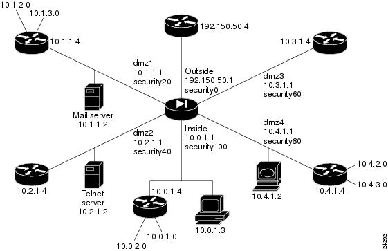
In , the PIX Firewall has six interfaces. In this configuration, there is no user authentication and no authorization. NAT (Network Address Translation) is in effect to translate addresses. In this example, users on all interfaces have access to all the servers and hosts on the inside, dmz1, dmz2, dmz3, and dmz4 interfaces can start connections.
This section includes the following topics:
•Guidelines for a Configuration with Six Interfaces
•IP Addresses for a Configuration with Six Interfaces
•Configuration for Six Interfaces
Figure 5-7 Six Interfaces with NAT
Configuring PIX Firewall for six interfaces is similar to the four interface example except that you have two more interfaces.
Guidelines for a Configuration with Six Interfaces
This section includes the following topics:
•Guidelines
•Higher Security Level to Lower Security Level Access
•Lower Security Level to Higher Security Level Access
Guidelines
The most important guidelines to remember follow:
•Higher to lower—To let users on a higher security level interface access hosts on a lower security interface, use the nat and global commands; for example, to let users on the inside interface access the mail server on the dmz2 interface. As seen in , the inside interface has a security level of 100 and the dmz2 interface has a security level of 40.
The nat command lets users access all hosts on all lower security level interfaces. The global command identifies the interface through which the nat access is permitted.
•Lower to higher—To let users on a lower security level interface access hosts on a higher security interface, use the static and conduit commands; for example, to let users on the dmz1 interface access the Telnet server on the dmz2 interface. As seen in , the dmz1 interface has a security level of 20 and the dmz2 interface has a security level of 40.
The static command lets users access specifically identified hosts on a single interface. The conduit command identifies the port or ports through which access is permitted.
The sections that follow provide more information on these guidelines.
Higher Security Level to Lower Security Level Access
To let users on each higher security level interface access servers on each lower security level interface, follow these steps:
Step 1 Letting higher security level interface users access a lower security level interface has two components: you use the nat command to specify from where users start connections, and you use the global command to specify to where access is permitted. You associate the nat and global commands together with the NAT ID, which in this example configuration is 1. The nat command lets users start connections from the specified interface to all lower security interfaces, the global command permits access to translated connections from any higher security level interface.
•To let users from the inside interface start connections on the dmz1, dmz2, dmz3, dmz4, and outside interfaces, use:
•To let users on the dmz1 interface start connections on the outside, use:
•To let users on the dmz2 interface start connections on the dmz1 and outside interfaces, use:
•To let users on the dmz3 interface start connections on the dmz1, dmz2, and outside interfaces, use:
•To let users on the dmz4 interface start connections on the dmz1, dmz2, dmz3, and outside interfaces, use:
Step 2 Create global pools for the connections to start on each lower level interface:
•To permit access to the outside interface for translated connections from the inside, dmz1, dmz2, dmz3, and dmz4 interfaces, use:
global (outside) 1 192.150.50.10-192.150.50.254
•To permit access to the dmz1 interface for translated connections from the inside, dmz2, dmz3, and dmz4 interfaces, use:
global (dmz1) 1 10.1.1.10-10.1.1.254
•To permit access to the dmz2 interface for translated connections from the inside, dmz3, and dmz4 interfaces, use:
global (dmz2) 1 10.2.1.10-10.2.1.254
•To permit access to the dmz3 interface for translated connections from the inside and dmz4 interfaces, use:
global (dmz3) 1 10.3.1.10-10.3.1.254
Lower Security Level to Higher Security Level Access
To let users on a lower security level interface access a server on a higher security level interface, use the static and conduit commands. The first IP address in the static command is the address users on the lower security level interface use when they want to access the server on the higher security level interface. The second IP address is the actual address of the server.
When you enter the static command statement in your configuration, always specify the security level of the interfaces as (higher,lower) and the IP addresses as lower and higher; for example:
static (inside,dmz1) 10.1.1.7 10.0.1.2
When users on the dmz1 interface access the Telnet server, they use IP address 10.1.1.7.
To let users on each lower security level interface access servers on each higher security level interface, follow these steps:
Step 1 To let users on the outside interface access the mail server on the dmz1 interface, use:
static (dmz1,outside) 192.150.50.5 10.1.1.2
conduit permit tcp host 192.150.50.5 eq smtp any
Step 2 To let users on the outside interface access the Telnet server on the dmz2 interface, use:
static (dmz2,outside) 192.150.50.6 10.2.1.2
conduit permit tcp host 192.150.50.6 eq telnet any
Step 3 To let users on the dmz1 interface access the Telnet server on the dmz2 interface, use:
static (dmz2,dmz1) 10.1.1.7 10.2.1.2
conduit permit tcp host 10.1.1.7 eq telnet any
All configuration command statements are explained in greater detail in .
Once you sketch out your network and map these steps to your IP addresses and servers, the four-interface configuration can become a simpler task.
IP Addresses for a Configuration with Six Interfaces
The addresses used in this configuration are as follows:
•The outside interface: 192.150.50.1 with static global addresses of 192.150.50.5 for the mail server on dmz1, 192.150.50.6 for the web server on dmz2, and 192.150.50.7 for the Telnet server on the inside. In addition, a pool of global addresses is defined as 192.150.50.10-192.150.50.254. A PAT (Port Address Translation) global is provided at 192.150.50.9.
•The dmz1 interface: 10.1.1.1 with static global addresses of 10.1.1.6 for the Telnet server on dmz2. A pool of global addresses is defined as 10.1.1.10-10.1.1.254.
•The dmz2 interface: 10.2.1.1 with a pool of global addresses of 10.2.1.10-10.2.1.254.
•The dmz3 interface: 10.3.1.1 with a pool of global addresses of 10.3.1.10-10.3.1.254.
•The dmz4 interface: 10.4.1.1 with a pool of global addresses of 10.4.1.10-10.4.1.254.
•The inside interface: 10.0.1.1 with a router at 10.0.1.4 and a host at 10.0.1.3.
In addition, static route command statements are required to permit access to the networks that connect to the routers. A static route command statement directs traffic meant for a network to the router on the interface. The format for a static route is shown in the following example:
route inside 10.0.2.0 255.255.255.0 10.0.1.4 1
This command statement instructs the PIX Firewall that when a packet needs to be sent to an address in the 10.0.2.0 network, send it to the router on the inside interface at 10.0.0.4.
Because there are routers on the inside, dmz1, and dmz4 interfaces with two networks connecting to each, six static route command statements are required—two for each interface.
Configuration for Six Interfaces
lists a six-interface configuration.
Table 5-7 Configuration with Six Interfaces
Configuration
|
Description
|
nameif ethernet0 outside security0
nameif ethernet1 inside security100
nameif ethernet2 dmz1 security20
nameif ethernet3 dmz2 security40
nameif ethernet4 dmz3 security60
nameif ethernet5 dmz4 security80
|
PIX Firewall provides nameif command statements for all interfaces. In this case, the default perimeter names were changed to dmz1 through dmz4.
|
|
PIX Firewall provides interface command statements for all six interfaces in the default configuration
|
ip address outside 192.150.50.1 255.255.255.0
ip address dmz1 10.1.1.1 255.255.255.0
ip address dmz2 10.2.1.1 255.255.255.0
ip address dmz3 10.3.1.1 255.255.255.0
ip address dmz4 10.4.1.1 255.255.255.0
ip address inside 10.0.1.1 255.255.255.0
|
Identify the IP address for each interface.
|
|
Specify the host name for the PIX Firewall. This name appears in the command line prompt.
|
|
Set the ARP timeout to 14,400 seconds (four hours). This command statement is provided in the default configuration.
|
|
Disable failover access.
|
|
Lets you use text strings instead of IP addresses, which makes your configuration easier to read.
|
|
Enable paging so that if after 24 lines of information displays, PIX Firewall pauses the listing and prompts you to continue.
|
logging buffered debugging
|
Enable syslog messages, which provide diagnostic information and status for the PIX Firewall. You can view the messages with the show logging command and clear the message buffer with the clear logging command.
|
|
Disable RIP attributes. Add command statements for the perimeter interfaces.
|
route outside 0.0.0.0 0.0.0.0 192.150.50.4 1
|
Set the outside default route to the router attached to the Internet.
|
route dmz1 10.1.2.0 255.255.255.0 10.1.1.4 1
route dmz1 10.1.3.0 255.255.255.0 10.1.1.4 1
|
Provide static routes so that packets destined for the 10.1.2.0 and 10.1.3.0 networks are sent to the 10.1.1.4 router on the dmz1 interface.
|
route dmz4 10.4.2.0 255.255.255.0 10.4.1.4 1
route dmz4 10.4.3.0 255.255.255.0 10.4.1.4 1
|
Provide static routes so that packets destined for the 10.4.2.0 and 10.4.3.0 networks are sent to the 10.4.1.4 router on the dmz4 interface.
|
route inside 10.0.2.0 255.255.255.0 10.0.1.4 1
route inside 10.0.3.0 255.255.255.0 10.0.1.4 1
|
Provide static routes so that packets destined for the 10.1.2.0 and 10.0.3.0 networks are sent to the 10.0.1.4 router on the inside interface.
|
conduit permit icmp any any
|
Allow inbound and outbound pings.
|
timeout xlate 3:00:00 conn 1:00:00
half-closed 0:10:00 udp 0:02:00
timeout rpc 0:10:00 h323 0:05:00
timeout uauth 0:05:00 absolute
|
Default values for the maximum duration that PIX Firewall resources can remain idle until being freed.
|
snmp-server community public
|
Specify that SNMP information may be accessed by internal hosts that know the community string, but PIX Firewall does not send trap information to any host.
|
|
Set the maximum transmission unit value for Ethernet access. You need to add the MTU command statements for the perimeter interfaces.
|
telnet 10.2.1.2 255.255.255.255
|
Give Telnet access to PIX Firewall console to users on the Telnet server on dmz2 host. PIX Firewall checks the interface IP address to ensure it is an internal interface. This lets users outside the network Telnet to the server and then access the PIX Firewall console from the server. This is one method that can be used to troubleshoot or administer a PIX Firewall from a remote location. Use the timeout command feature to let Telnet console sessions stay idle up to 15 minutes before PIX Firewall closes the connection. The default is 5 minutes.
|
|
Let inside users start connections on all lower security level interfaces: dmz1, dmz2, dmz3, dmz4, and the outside.
|
|
Let dmz1 users start connections on the lower security level interface: the outside.
|
|
Let dmz2 users start connections on all lower security level interfaces: dmz1 and the outside.
|
|
Let dmz3 users start connections on all lower security level interfaces: dmz1, dmz2, and the outside.
|
|
Let dmz4 users start connections on all lower security level interfaces: dmz1, dmz2, dmz3, and the outside.
|
global (outside) 1 192.150.50.10-192.150.50.254
netmask 255.255.255.0
global (outside) 1 192.150.50.9 netmask
255.255.255.0
|
Create a pool of global addresses for the outside interface to permit users on all other interfaces to access the Internet. Because there are potentially more than 244 users on the 3 other interfaces, add a PAT global to handle overflow.
|
global (dmz1) 1 10.1.1.10-10.1.1.254 netmask
255.255.255.0
|
Give access to the dmz1 interface for users on the dmz2, dmz3, dmz4, and the inside interfaces. This global command statement lets users on access these interfaces access the dmz1 mail server and provides access to the 10.1.2.0 and 10.1.3.0 networks.
|
global (dmz2) 1 10.2.1.10-10.2.1.254 netmask
255.255.255.0
|
Give access to the dmz2 interface for users on the inside interface. This global command statement lets inside users on the dmz3, dmz4, and inside access to the Telnet server of dmz2.
|
global (dmz3) 1 10.3.1.10-10.3.1.254
|
Give access to the dmz3 interface for users on the inside and dmz4 interfaces.
|
global (dmz4) 1 10.4.1.10-10.4.1.254 netmask
255.255.255.0
|
Give access to the dmz4 interface for users on the inside interface which also permits access to the 10.4.2.0 and 10.4.3.0 networks connected to the 10.4.1.4 router.
|
static (dmz1,outside) 192.150.50.6 10.1.1.2 netmask
255.255.255.255
conduit permit tcp host 192.150.50.6 eq smtp any
|
Give outside users access to the mailserver on the dmz1 interface.
|
static (dmz2,outside) 192.159.50.7 10.2.1.2 netmask
255.255.255.255
conduit permit tcp host 192.150.50.7 eq telnet any
|
Give outside users access to the Telnet server on the dmz2 interface.
|
static (dmz2,dmz1) 10.1.1.6 10.2.1.2 netmask
255.255.255.255
conduit permit tcp host 10.1.1.6 eq telnet any
|
Give dmz1 users access to the Telnet server on the dmz2 interface.
|
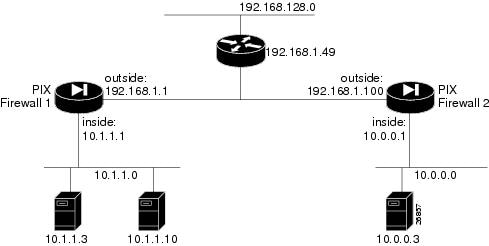
IPSec with Manual Keys
In this example, two PIX Firewall units are used to create a virtual private network (VPN) between the networks on each firewall unit's inside interface. This network is part of an intranet and therefore uses RFC 1918 addressing throughout.
In this example, the VPN is created without the use of IKE or a certificate authority.
Figure 5-8 Two Interfaces for IPSec Access
The interfaces are as follows:
•PIX Firewall 1:
•inside: 10.1.1.1
•outside: 192.168.1.1
•PIX Firewall 2:
•inside: 10.0.0.1
•outside: 192.168.1.100
The topics included in this section are:
•PIX Firewall 1 Configuration
•PIX Firewall 2 Configuration
PIX Firewall 1 Configuration
To program the PIX Firewall 1 unit for IPSec:
Step 1 Create a crypto map command statement.
Step 2 Create the access-list entries to select traffic for this policy.
Note For manual keying, only one access-list permit command statement is permitted in the configuration.
Step 3 Create the transform set for the crypto command statement entry.
Step 4 Define cryptographic state informations. These include SPI, and the necessary keys for manual keying and policy negotiation for ISAKMP.
Step 5 Repeat steps 1-4 for each group of policies.
Step 6 Associate the crypto map command statement with an interface.
lists the configuration for PIX Firewall 1.
Table 5-8 Two Interfaces with IPSec—PIX Firewall 1 Configuration
Configuration
|
Description
|
nameif ethernet0 outside security0
nameif ethernet1 inside security100
|
PIX Firewall provides nameif and interface command statements for the interfaces in the default configuration.
|
ip address outside 192.168.1.1 255.255.255.0
ip address inside 10.1.1.1 255.255.255.0
|
Identify the IP addresses for both interfaces.
|
enable password 8Ry2YjIyt7RRXU24 encrypted
passwd 2KFQnbNIdI.2KYOU encrypted
|
Default values for the privileged mode password and host name.
|
fixup protocol sqlnet 1521
|
Default values that assign a port value for each service that the PIX Firewall provides special handling for.
|
failover ip address outside 0.0.0.0
failover ip address inside 0.0.0.0
|
Default settings to disable failover.
|
|
Default settings that lets you use text strings instead of IP addresses, which makes your configuration easier to read, and sets the screen output so 24 lines display at a time before you are prompted to continue.
|
logging console debugging
|
Enable syslog output to the console to receive debugging messages.
|
|
Default Ethernet MTU settings.
|
|
Default value for the ARP timeout set to 14,400 seconds (four hours). Entries are kept in the ARP table for four hours before they are flushed.
|
|
Permit all inside users to start outbound connections using the translated IP addresses from the global pool.
|
global (outside) 1
128.120.56.100-128.120.56.150
|
Create a pool of global addresses that translated addresses use when they exit the firewall from the protected networks to the unprotected networks. The global command statement is associated with a nat command statement by the nat_ID, which in this example is 1.
|
static (inside,outside) 192.168.128.3
10.1.1.3 netmask 255.255.255.255 0 0
|
Create an inbound access address on the outside of the intranet on the 192.168.128.0 network so that the 10.1.1.3 server on PIX Firewall 1 is accessible from that network.
|
|
Default settings to disable RIP listening and broadcasting.
|
route outside 0.0.0.0 0.0.0.0 192.168.1.49 1
|
Establish a default route on the outside interface so that packets are routed to the router on the outside interface.
|
route inside 10.1.1.0 255.255.255.0 10.1.1.3 1
|
Create a static route so that all packets destined for the 10.1.1.0 network are routed to the server at 10.1.1.3.
|
timeout xlate 3:00:00 conn 1:00:00 half-closed
0:10:00 udp 0:02:00
timeout rpc 0:10:00 h323 0:05:00
timeout uauth 0:05:00 absolute
|
Default timeout settings.
|
snmp-server community public
no snmp-server enable traps
|
Default settings that disable SNMP access.
|
sysopt connection tcpmss 1380
|
Set the TCP maximum segment size to 1380 bytes. This is recommended for data over the encrypted VPN channel. This value is set by default but does not display in the default configuration. It does not need to be specified in a configuration.
|
sysopt connection permit-ipsec
|
Enable IPSec traffic to bypass the check of conduit or access-group command statements. If you disable this option, you need to add a conduit command statement to your configuration to allow the required set of IPSec traffic.
|
crypto map mymap 10 ipsec-manual
|
Create a crypto map called "mymap" and specify with the ipsec-manual option that IKE will not be used to establish the IPSec security association.
|
crypto ipsec transform-set myset ah-md5-hmac
esp-des
crypto map mymap 10 set transform-set myset
|
Establish the transform set as myset, enable MD5 AH, and enable ESP with 56-bit DES encryption. Then associate the transform set with the crypto map entry.
The transform set is used in the IPSec security association negotiation to protect the data flows specified by that crypto map entry's access list. Because IKE is not used to establish security associations, a single transform set must be used. The transform set is not negotiated.
|
access-list 10 permit ip host 192.168.128.3
host 209.165.200.225
|
Permit TCP traffic, and permit IP access from some external host on another network.
|
crypto map mymap 10 match address 10
|
Associate the map entry with the access list.
|
crypto map mymap 10 set peer 192.168.1.100
|
Establish PIX Firewall 2 as the peer. When IKE is not used, as in this example, only one peer is specified.
|
crypto map mymap 10 set session-key inbound ah
400 123456789A123456789A123456789A123456789A
|
Establish the inbound AH session key. The SPI (security parameter index) is set to 400 and the string of characters after the SPI is the session key specified in hexadecimal.
|
crypto map mymap 10 set session-key outbound
ah 300
123456789A123456789A123456789A123456789A
|
Establish the outbound AH session key. The SPI is set to 300 and the string of characters after the SPI is the session key specified in hexadecimal.
|
crypto map mymap 10 set session-key inbound
esp 400 cipher abcd1234abcd1234 authenticator
123456789A123456789A123456789A123456789A
|
Establish the inbound ESP session key. The SPI is set to 400. The cipher option indicates that the key string that follows the option is to be used with the ESP encryption transform. The authenticator option Indicates that the key string that follows the option is to be used with the ESP authentication transform. This argument is required only when the crypto map entry's transform set includes an ESP authentication transform.
|
crypto map mymap 10 set session-key outbound
esp 300 cipher abcd1234abcd1234 authenticator
123456789A123456789A123456789A123456789A
|
Establish the outbound ESP session key. The SPI is set to 300 and the cipher and authenticator keys are set to the same values as the inbound command statement.
|
|
Default values for the duration in minutes that a Telnet console session can be idle before being logged off, and for the number of characters wide that display during the console session.
|
PIX Firewall 2 Configuration
To program the PIX Firewall 2 unit for IPSec:
Step 1 Create a crypto map command statement.
Step 2 Create the access-list entries to select traffic for this policy.
Note For manual keying, only one access-list permit command statement is permitted in the configuration.
Step 3 Create the transform set for the crypto command statement entry.
Step 4 Define cryptographic state informations. These include SPI, and the necessary keys for manual keying and policy negotiation for ISAKMP.
Step 5 Repeat steps 1-4 for each group of policies.
Step 6 Associate the crypto map command statement with an interface.
lists the configuration for PIX Firewall 2.
Table 5-9 Two Interfaces with IPSec—PIX Firewall 2 Configuration
Configuration
|
Description
|
nameif ethernet0 outside security0
nameif ethernet1 inside security100
|
PIX Firewall provides nameif and interface command statements for the interfaces in the default configuration.
|
ip address outside 192.150.50.3 255.255.255.0
ip address inside 10.0.0.3 255.255.255.0
|
Identify the IP addresses for both interfaces.
|
enable password 8Ry2YjIyt7RRXU24 encrypted
passwd 2KFQnbNIdI.2KYOU encrypted
|
Default values for the privileged mode password and host name.
|
fixup protocol sqlnet 1521
|
Default values that assign a port value for each service that the PIX Firewall provides special handling for.
|
failover ip address outside 0.0.0.0
failover ip address inside 0.0.0.0
|
Default settings to disable failover.
|
|
Default settings that lets you use text strings instead of IP addresses, which makes your configuration easier to read, and sets the screen output so 24 lines display at a time before you are prompted to continue.
|
logging console debugging
|
Enable syslog output to the console to receive debugging messages.
|
|
Default Ethernet MTU settings.
|
|
Default value for the ARP timeout set to 14,400 seconds (four hours). Entries are kept in the ARP table for four hours before they are flushed.
|
|
Permit all inside users to start outbound connections using the translated IP addresses from the global pool.
|
static (inside,outside) 209.165.200.225
10.0.0.3 netmask 255.255.255.255 0 0
|
Create a static mapping between the inside host and an external address beyond the outside router.
|
access-list 10 permit ip host 209.165.200.225
host 192.168.128.3
|
Permit access to the static mapping from the 192.168.128.0 network outside the router.
|
route outside 0.0.0.0 0.0.0.0 192.168.1.49 1
route inside 10.0.0.0 255.255.255.0 10.0.0.3 1
|
Create the default route to the outside router, and a static route to send packets on the inside interface.
|
timeout xlate 3:00:00 conn 1:00:00 half-closed
0:10:00 udp 0:02:00
timeout rpc 0:10:00 h323 0:05:00
timeout uauth 0:05:00 absolute
|
Default timeout settings.
|
snmp-server community public
no snmp-server enable traps
|
Default settings that disable SNMP access.
|
|
Default settings to disable RIP listening and broadcasting.
|
crypto map mymap 10 ipsec-manual
|
Create a crypto map called "mymap" and specify with the ipsec-manual option that IKE will not be used to establish the IPSec security association.
|
crypto ipsec transform-set myset ah-md5-hmac
esp-des
crypto map mymap 10 set transform-set myset
|
Establish the transform set as myset, enable MD5 AH, and enable ESP with 56-bit DES encryption. Then associate the transform set with the crypto map entry.
The transform set is used in the IPSec security association negotiation to protect the data flows specified by that crypto map entry's access list. Because IKE is not used to establish security associations, a single transform set must be used. The transform set is not negotiated.
|
sysopt connection tcpmss 1380
|
Set the TCP maximum segment size to 1380 bytes. This is recommended for data over the encrypted VPN channel. This value is set by default but does not display in the default configuration.
|
crypto map mymap 10 match address 10
|
Associate the map entry with the access list.
|
crypto map mymap 10 set peer 192.168.1.1
|
Establish PIX Firewall 1 as the peer. When IKE is not used, as in this example, only one peer is specified.
|
crypto map mymap 10 set session-key inbound ah
300 123456789A123456789A123456789A123456789A
|
Establish the inbound AH session key. The SPI (security parameter index) is set to 300 and the string of characters after the SPI is the session key specified in hexadecimal. The SPI for PIX Firewall 2 is opposite of the values specified for PIX Firewall 1 (PIX Firewall 1 has an inbound SPI of 400 and an outbound SPI of 300).
|
crypto map mymap 10 set session-key outbound
ah 400
123456789A123456789A123456789A123456789A
|
Establish the outbound AH session key. The SPI is set to 400 and the string of characters after the SPI is the session key specified in hexadecimal.
|
crypto map mymap 10 set session-key inbound
esp 300 cipher abcd1234abcd1234 authenticator
123456789A123456789A123456789A123456789A
|
Establish the inbound ESP session key. The SPI is set to 300. The cipher option indicates that the key string that follows the option is to be used with the ESP encryption transform. The authenticator option Indicates that the key string that follows the option is to be used with the ESP authentication transform. This argument is required only when the crypto map entry's transform set includes an ESP authentication transform.
|
crypto map mymap 10 set session-key outbound
esp 400 cipher abcd1234abcd1234 authenticator
123456789A123456789A123456789A123456789A
|
Establish the outbound ESP session key. The SPI is set to 400 and the cipher and authenticator keys are set to the same values as the inbound command statement.
|
|
Default values for the duration in minutes that a Telnet console session can be idle before being logged off, and for the number of characters wide that display during the console session.
|
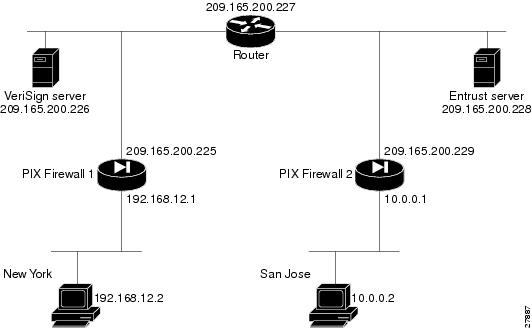
VPN Tunnel Using Pre-shared Keys without NAT
This section includes the following topics:
•Configuring PIX Firewall 1 for VPN Tunneling
•Configuring PIX Firewall 2 for VPN Tunneling
This example uses the network diagram shown in :
Figure 5-9 VPN Tunnel Network
Configuring PIX Firewall 1 for VPN Tunneling
To configure PIX Firewall 1:
Step 1 Define a host name:
Step 2 Define the domain name:
Step 3 Create a net static:
static (inside,outside) 192.168.12.0 192.168.12.0
Step 4 Configure an ISAKMP policy:
isakmp policy 9 authentication pre-share
isakmp policy 9 encr 3des
Step 5 Configure pre-shared key and associate with the peer:
crypto isakmp key cisco1234 address 209.165.200.229
Step 6 Configure the supported IPSec transforms:
crypto ipsec transform-set strong esp-3des esp-sha-hmac
Step 7 Create an access list:
access-list 90 permit ip 192.168.12.0 255.255.255.0 10.0.0.0 255.0.0.0
Step 8 Define a crypto map:
crypto map toSanJose 20 ipsec-isakmp
crypto map toSanJose 20 match address 90
crypto map toSanJose 20 set transform-set strong
crypto map toSanJose 20 set peer 209.165.200.229
Step 9 Apply the crypto map to the outside interface:
crypto map toSanJose interface outside
Step 10 Specify that IPSec traffic be implicitly trusted (permitted):
sysopt connection permit-ipsec
lists the configuration for PIX Firewall 1:
Table 5-10 PIX Firewall 1 VPN Tunnel Configuration
Configuration
|
Description
|
nameif ethernet0 outside security0
nameif ethernet1 inside security100
|
PIX Firewall provides nameif and interface command statements for the interfaces in the default configuration.
|
enable password 8Ry2YjIyt7RRXU24 encrypted
passwd 2KFQnbNIdI.2KYOU encrypted
|
Default values for the privileged mode password and the Telnet password.
|
|
Define a host name for the PIX Firewall.
|
|
Set the domain name.
|
fixup protocol sqlnet 1521
|
Default fixup protocol values that define port usage.
|
|
Default values that let you use names instead of an IP addresses, display 24 lines of text before you are prompted to continue, and disable syslog output.
|
|
Set the maximum transmission unit values for the Ethernet interfaces.
|
ip address outside 209.165.200.225
255.255.255.224
ip address inside 192.168.12.1 255.255.255.0
|
The IP addresses for each PIX Firewall interface.
|
failover ip address outside 0.0.0.0
failover ip address inside 0.0.0.0
|
Default values to disable failover.
|
|
Default value specifying that the ARP cache be reinitialized every four hours.
|
nat (inside) 0 0.0.0.0 0.0.0.0 0 0
|
Disable NAT for the inside interface.
|
static (inside,outside) 192.168.12.0
192.168.12.0 netmask 255.255.255.0 0 0
access-list 90 permit ip 192.168.12.0
255.255.255.0 10.0.0.0 255.0.0.0
|
Create a static command statement for access between the inside and outside interfaces so that all hosts on the 192.168.12.0 network are accessible on the outside interface. The access-list command statement permits IP traffic on all hosts on the inside network to be accessed by the hosts on PIX Firewall 2.
|
|
Default values to disable RIP listening or broadcasting. However, the inside interface does listen for RIP broadcasts.
|
route outside 0.0.0.0 0.0.0.0 209.165.200.227 1
|
Specify the router on the outside interface for default routes.
|
timeout xlate 3:00:00 conn 1:00:00 half-closed
0:10:00 udp 0:02:00
timeout rpc 0:10:00 h323 0:05:00
timeout uauth 0:05:00 absolute
|
Default timer values.
|
aaa-server TACACS+ protocol tacacs+
aaa-server RADIUS protocol radius
|
Default values that permit access to the TACACS+ or RADIUS protocols; however, AAA is not used in this configuration.
|
snmp-server community public
no snmp-server enable traps
|
Default values to disable SNMP access.
|
crypto ipsec transform-set strong esp-3des
esp-sha-hmac
crypto map toSanJose 20 ipsec-isakmp
crypto map toSanJose 20 match address 90
crypto map toSanJose 20 set peer 209.165.200.229
crypto map toSanJose 20 set transform-set strong
crypto map toSanJose interface outside
|
Define the crypto map transforms, specify ISAKMP access, match the map to the access list (both use ID 90 to be associated), set the tunnel peer to be the outside interface IP address of PIX Firewall 2 (209.165.200.229), and apply the crypto map to the outside interface.
|
isakmp key cisco1234 address 209.165.200.229
netmask 255.255.255.255
isakmp policy 9 authentication pre-share
isakmp policy 9 encryption 3des
|
Configure the ISAKMP policy.
|
sysopt connection permit-ipsec
|
Specify that IPSec traffic be implicitly trusted (permitted).
|
|
Default values for how long a Telnet console session can be idle and that a console session should display up to 80 characters wide on the console computer.
|
Configuring PIX Firewall 2 for VPN Tunneling
To configure PIX Firewall 2:
Step 1 Define a host name:
Step 2 Define the domain name:
Step 3 Create a net static:
static (inside,outside) 10.0.0.0 10.0.0.0
Step 4 Configure the ISAKMP policy:
isakmp policy 8 authentication pre-share
Step 5 Configure a pre-shared key and associate it with the peer:
crypto isakmp key cisco1234 address 209.165.200.225
Step 6 Configure IPSec supported transforms:
crypto ipsec transform-set strong esp-3des esp-sha-hmac
Step 7 Create an access list:
access-list 80 permit ip 10.0.0.0 255.0.0.0 192.168.12.0 255.255.255.0
Step 8 Define a crypto map:
crypto map newyork 10 ipsec-isakmp
crypto map newyork 10 match address 80
crypto map newyork 10 set transform-set strong
crypto map newyork 10 set peer 209.165.200.225
Step 9 Apply the crypto map to the interface:
crypto map newyork interface outside
Step 10 Specify that IPSec traffic be implicitly trusted (permitted):
sysopt connection permit-ipsec
lists the configuration for PIX Firewall 2:
Table 5-11 PIX Firewall 2 VPN Tunnel Configuration
Configuration
|
Description
|
nameif ethernet0 outside security0
nameif ethernet1 inside security100
nameif ethernet2 dmz security50
nameif ethernet3 perimeter security40
|
PIX Firewall provides nameif command statements for interfaces in the default configuration. In addition, the default configuration provides default names for the perimeter interfaces, but in this case, the configuration requires different names and security levels for the perimeter interfaces.
|
enable password 8Ry2YjIyt7RRXU24 encrypted
passwd 2KFQnbNIdI.2KYOU encrypted
|
Default values for the privileged mode password and the Telnet password.
|
|
Define a host name for the PIX Firewall.
|
|
Set the domain name.
|
fixup protocol sqlnet 1521
|
Default fixup protocol values that define port usage.
|
|
Default values that let you use names instead of an IP addresses, display 24 lines of text before you are prompted to continue, and disable syslog output.
|
|
Default interface definitions indicating that each Ethernet interface has automatic sensing capabilities to determine line speed and duplex.
|
|
Set the maximum transmission unit values for the Ethernet interfaces.
|
ip address outside 209.165.200.229
255.255.255.224
ip address inside 10.0.0.1 255.0.0.0
ip address dmz 192.168.101.1 255.255.255.0
ip address perimeter 192.168.102.1
255.255.255.0
|
The IP addresses for each PIX Firewall interface.
|
failover ip address outside 0.0.0.0
failover ip address inside 0.0.0.0
failover ip address dmz 0.0.0.0
failover ip address perimeter 0.0.0.0
|
Default values to disable failover.
|
|
Default value specifying that the ARP cache be reinitialized every four hours.
|
nat (inside) 0 0.0.0.0 0.0.0.0 0 0
|
Disable NAT for the inside interface.
|
static (inside,outside) 10.0.0.0 10.0.0.0
netmask 255.0.0.0 0 0
access-list 80 permit ip 10.0.0.0 255.0.0.0
192.168.12.0 255.255.255.0
|
Create a static command statement for access between the inside and outside interfaces so that all hosts on the 10.0.0.0 network are accessible on the outside interface. The access-list command statement permits IP traffic on all hosts on the inside network to be accessed by the hosts on PIX Firewall 1.
|
|
Default values to disable RIP listening or broadcasting.
|
route outside 0.0.0.0 0.0.0.0 209.165.200.227 1
|
Specify the router on the outside interface for default routes.
|
timeout xlate 3:00:00 conn 1:00:00 half-closed
0:10:00 udp 0:02:00
timeout rpc 0:10:00 h323 0:05:00
timeout uauth 0:05:00 absolute
|
Default timer values.
|
aaa-server TACACS+ protocol tacacs+
aaa-server RADIUS protocol radius
|
Default values that permit access to the TACACS+ or RADIUS protocols; however, AAA is not used in this configuration.
|
snmp-server community public
no snmp-server enable traps
|
Default values to disable SNMP access.
|
crypto ipsec transform-set strong esp-3des
esp-sha-hmac
crypto map newyork 10 ipsec-isakmp
crypto map newyork 10 match address 80
crypto map newyork 10 set peer 209.165.200.225
crypto map newyork 10 set transform-set strong
crypto map newyork interface outside
|
Define the crypto map transforms, specify ISAKMP access, match the map to the access list (both use ID 80 to be associated), set the tunnel peer to be the outside interface IP address of PIX Firewall 1 (209.165.200.225), and apply the crypto map to the outside interface.
|
isakmp key cisco1234 address 209.165.200.225
netmask 255.255.255.255
isakmp policy 8 authentication pre-share
isakmp policy 8 encryption 3des
|
Configure the ISAKMP policy.
|
sysopt connection permit-ipsec
|
Specify that IPSec traffic be implicitly trusted (permitted).
|
|
Default values for how long a Telnet console session can be idle and that a console session should display up to 80 characters wide on the console computer.
|
VPN Tunnel Using VeriSign Digital Certificates
This section includes the following topics:
•Configuring PIX Firewall 1 for a VeriSign Certificate
•Configuring PIX Firewall 2 for a VeriSign Certificate
This example uses the network diagram shown in :
Figure 5-10 VPN Tunnel Network
Configuring PIX Firewall 1 for a VeriSign Certificate
To configure PIX Firewall 1:
Step 1 Define a host name:
Step 2 Define the domain name:
Step 3 Create a net static:
static (inside,outside) 192.168.12.0 192.168.12.0
Step 4 Configure an ISAKMP policy:
isakmp policy 8 auth rsa-signature
Step 5 Define VeriSign-related enrollment commands:
ca identity example.com 209.165.200.226
ca configure example.com ca 2 100 crloptional
These commands are stored in the configuration. "2" is the retry period, "100" is the retry count, and the crloptional option disables CRL checking.
Step 6 Generate an RSA key pair:
This command is not stored in the configuration.
Step 7 Get the public key and the certificate of the CA server:
ca authenticate example.com
This command is not stored in the configuration:
Step 8 Contact your CA administrator and send your certificate request.
ca enroll example.com abcdef
"abcdef" is a challenge password. This can be anything. This command is not stored in the configuration.
Step 9 Configure supported IPSec transforms.
crypto ipsec transform-set strong esp-3des esp-sha-hmac
Step 10 Save keys, certificates, and CRLs in Flash memory:
Note Use the ca save all command any time you add, change, or delete ca commands in the configuration. This command is not stored in the configuration.
Step 11 Create a partial access list:
access-list 90 permit ip 192.168.12.0 255.255.255.0 10.0.0.0 255.0.0.0
Step 12 Define a crypto map:
crypto map toSanJose 20 ipsec-isakmp
crypto map toSanJose 20 match address 90
crypto map toSanJose 20 set transform-set strong
crypto map toSanJose 20 set peer 209.165.200.229
Step 13 Apply the crypto map to the outside interface:
crypto map toSanJose interface outside
Step 14 Specify that IPSec traffic be implicitly trusted (permitted):
sysopt connection permit-ipsec
lists the configuration for PIX Firewall 1:
Table 5-12 PIX Firewall 1 VPN Tunnel Configuration
Configuration
|
Description
|
nameif ethernet0 outside security0
nameif ethernet1 inside security100
|
PIX Firewall provides nameif command statements for the interfaces in the configuration.
|
enable password 8Ry2YjIyt7RRXU24 encrypted
passwd 2KFQnbNIdI.2KYOU encrypted
|
Default values for the privileged mode password and the Telnet password.
|
|
Define a host name for the PIX Firewall.
|
|
Set the domain name.
|
fixup protocol sqlnet 1521
|
Default fixup protocol values that define port usage.
|
|
Default values that let you use names instead of an IP addresses, display 24 lines of text before you are prompted to continue, and disable syslog output.
|
|
Default interface definitions indicating that each Ethernet interface has automatic sensing capabilities to determine line speed and duplex.
|
|
Set the maximum transmission unit values for the Ethernet interfaces.
|
ip address outside 209.165.200.225
255.255.255.224
ip address inside 192.168.12.1 255.255.255.0
|
The IP addresses for each PIX Firewall interface.
|
failover ip address outside 0.0.0.0
failover ip address inside 0.0.0.0
|
Default values to disable failover.
|
|
Default value specifying that the ARP cache be reinitialized every four hours.
|
nat (inside) 0 0.0.0.0 0.0.0.0 0 0
|
Disable NAT for the inside interface.
|
static (inside,outside) 192.168.12.0
192.168.12.0 netmask 255.255.255.0 0 0
access-list 90 permit ip 192.168.12.0
255.255.255.0 10.0.0.0 255.0.0.0
|
Create a static command statement for access between the inside and outside interfaces so that all hosts on the 192.168.12.0 network are accessible on the outside interface. The access-list command statement permits IP traffic on all hosts on the inside network to be accessed by the hosts on PIX Firewall 2.
|
|
Default values to disable RIP listening or broadcasting. However, the inside interface does listen for RIP broadcasts.
|
route outside 0.0.0.0 0.0.0.0 209.165.200.227 1
|
Specify the router on the outside interface for default routes.
|
timeout xlate 3:00:00 conn 1:00:00 half-closed
0:10:00 udp 0:02:00
timeout rpc 0:10:00 h323 0:05:00
timeout uauth 0:05:00 absolute
|
Default timer values.
|
aaa-server TACACS+ protocol tacacs+
aaa-server RADIUS protocol radius
|
Default values that permit access to the TACACS+ or RADIUS protocols; however, AAA is not used in this configuration.
|
snmp-server community public
no snmp-server enable traps
|
Default values to disable SNMP access.
|
crypto ipsec transform-set strong esp-3des
esp-sha-hmac
crypto map toSanJose 20 ipsec-isakmp
crypto map toSanJose 20 match address 90
crypto map toSanJose 20 set peer 209.165.200.229
crypto map toSanJose 20 set transform-set strong
crypto map toSanJose interface outside
|
Define the crypto map transforms, specify ISAKMP access, match the map to the access list (both use ID 90 to be associated), set the tunnel peer to be the outside interface IP address of PIX Firewall 2 (209.165.200.229), and apply the crypto map to the outside interface.
|
isakmp policy 9 encryption 3des
|
Configure the ISAKMP policy.
|
ca identity example.com
209.165.200.226:cgi-bin/pkiclient.exe
ca configure example.com ca 1 100 crloptional
|
Define VeriSign-related enrollment commands.
|
sysopt connection permit-ipsec
|
Specify that IPSec traffic be implicitly trusted (permitted).
|
|
Default values for how long a Telnet console session can be idle and that a console session should display up to 80 characters wide on the console computer.
|
Configuring PIX Firewall 2 for a VeriSign Certificate
To configure PIX Firewall 2:
Step 1 Define a host name:
Step 2 Define the domain name:
Step 3 Create a net static:
static (inside,outside) 192.168.12.0 192.168.12.0
Step 4 Configure an ISAKMP policy:
isakmp policy 8 auth rsa-signature
Step 5 Define VeriSign-related enrollment commands:
ca identity example.com 209.165.200.226
ca configure example.com ca 1 20 crloptional
These commands are stored in the configuration. 1 is the retry period, 20 is the retry count, and the crloptional option disables CRL checking.
Step 6 Generate an RSA key pair:
This command is entered at the command line and does not get stored in the configuration.
Step 7 Get the public key and the certificate of the CA server:
ca authenticate example.com
This command is entered at the command line and does not get stored in the configuration.
Step 8 Contact your CA administrator and send your certificate request:
ca enroll example.com abcdef
"abcdef" is a challenge password. This can be anything. This command is entered at the command line and does not get stored in the configuration.
Step 9 Configure supported IPSec transforms:
crypto ipsec transform-set strong esp-3des esp-sha-hmac
Step 10 Save keys, certificates, and CRLs in Flash memory:
Note Use the ca save all command any time you add, change, or delete ca commands in the configuration. This command is not stored in the configuration.
Step 11 Create a partial access list:
access-list 80 permit ip 10.0.0.0 255.0.0.0 192.168.12.0 255.255.255.0
Step 12 Define a crypto map:
crypto map newyork 10 ipsec-isakmp
crypto map newyork 10 match address 80
crypto map newyork 10 set transform-set strong
crypto map newyork 10 set peer 209.165.200.225
Step 13 Apply the crypto map to the outside interface:
crypto map toSanJose interface outside
Step 14 Specify that IPSec traffic be implicitly trusted (permitted):
sysopt connection permit-ipsec
lists the configuration for PIX Firewall 2:
Table 5-13 PIX Firewall 2 VPN Tunnel Configuration
Configuration
|
Description
|
nameif ethernet0 outside security0
nameif ethernet1 inside security100
nameif ethernet2 dmz security50
nameif ethernet3 perimeter security40
|
PIX Firewall provides nameif command statements interfaces in the default configuration, but in this case, the configuration required different names and security levels for the perimeter interfaces.
|
enable password 8Ry2YjIyt7RRXU24 encrypted
passwd 2KFQnbNIdI.2KYOU encrypted
|
Default values for the privileged mode password and the Telnet password.
|
|
Define a host name for the PIX Firewall.
|
|
Set the domain name.
|
fixup protocol sqlnet 1521
|
Default fixup protocol values that define port usage.
|
|
Default values that let you use names instead of an IP addresses, display 24 lines of text before you are prompted to continue, and disable syslog output.
|
|
Default interface definitions indicating that each Ethernet interface has automatic sensing capabilities to determine line speed and duplex.
|
|
Set the maximum transmission unit values for the Ethernet interfaces.
|
ip address outside 209.165.200.229
255.255.255.224
ip address inside 10.0.0.1 255.0.0.0
ip address dmz 192.168.101.1 255.255.255.0
ip address perimeter 192.168.102.1
255.255.255.0
|
The IP addresses for each PIX Firewall interface.
|
failover ip address outside 0.0.0.0
failover ip address inside 0.0.0.0
failover ip address dmz 0.0.0.0
failover ip address perimeter 0.0.0.0
|
Default values to disable failover.
|
|
Default value specifying that the ARP cache be reinitialized every four hours.
|
nat (inside) 0 10.0.0.0 255.0.0.0 0 0
|
Disable NAT for the inside interface.
|
static (inside,outside) 10.0.0.0 10.0.0.0
netmask 255.0.0.0 0 0
access-list 80 permit ip 10.0.0.0 255.0.0.0
192.168.12.0 255.255.255.0
|
Create a static command statement for access between the inside and outside interfaces so that all hosts on the 10.0.0.0 network are accessible on the outside interface. The access-list command statement permits IP traffic on all hosts on the inside network to be accessed by the hosts on PIX Firewall 1.
|
|
Default values to disable RIP listening or broadcasting.
|
route outside 0.0.0.0 0.0.0.0 209.165.200.227 1
|
Specify the router on the outside interface for default routes.
|
timeout xlate 3:00:00 conn 1:00:00 half-closed
0:10:00 udp 0:02:00
timeout rpc 0:10:00 h323 0:05:00
timeout uauth 0:05:00 absolute
|
Default timer values.
|
aaa-server TACACS+ protocol tacacs+
aaa-server RADIUS protocol radius
|
Default values that permit access to the TACACS+ or RADIUS protocols; however, AAA is not used in this configuration.
|
snmp-server community public
no snmp-server enable traps
|
Default values to disable SNMP access.
|
crypto ipsec transform-set strong esp-3des
esp-sha-hmac
crypto map newyork 10 ipsec-isakmp
crypto map newyork 10 match address 80
crypto map newyork 10 set peer 209.165.200.225
crypto map newyork 10 set transform-set strong
crypto map newyork interface outside
|
Define the crypto map transforms, specify ISAKMP access, match the map to the access list (both use ID 80 to be associated), set the tunnel peer to be the outside interface IP address of PIX Firewall 1 (209.165.200.225), and apply the crypto map to the outside interface.
|
isakmp key cisco1234 address 209.165.200.225
netmask 255.255.255.255
isakmp policy 8 encryption 3des
|
Configure the ISAKMP policy.
|
ca identity example.com
209.165.200.226:cgi-bin/pkiclient.exe
ca configure example.com ca 1 20 crloptional
|
Define VeriSign-related enrollment commands.
|
sysopt connection permit-ipsec
|
Specify that IPSec traffic be implicitly trusted (permitted).
|
|
Default values for how long a Telnet console session can be idle and that a console session should display up to 80 characters wide on the console computer.
|
VPN Tunnel Using Entrust Digital Certificates
This section includes the following topics:
•Configuring PIX Firewall 1 for an Entrust Certificate
•Configuring PIX Firewall 2 for an Entrust Certificate
This example uses the network diagram shown in :
Figure 5-11 VPN Tunnel Network
Configuring PIX Firewall 1 for an Entrust Certificate
To configure PIX Firewall 1:
Step 1 Define a host name:
Step 2 Define the domain name:
Step 3 Create a net static:
static (inside,outside) 192.168.12.0 192.168.12.0
Step 4 Configure an ISAKMP policy:
isakmp policy 8 auth rsa-signature
Step 5 Define Entrust-related enrollment commands:
ca identity abcd 209.165.200.228 209.165.200.228
ca configure abcd ra 1 20 crloptional
These commands are stored in the configuration. 1 is the retry period, 20 is the retry count, and the crloptional option disables CRL checking.
Step 6 Generate an RSA key pair:
ca generate rsa specialkey 512
This command is entered at the command line and does not get stored in the configuration.
Step 7 Get the public key and the certificate of the CA server:
This command is entered at the command line and does not get stored in the configuration.
Step 8 Contact your CA administrator and send your certificate request:
"cisco" is a challenge password. This can be anything. This command is entered at the command line and does not get stored in the configuration.
Step 9 Configure supported IPSec transforms:
crypto ipsec transform-set strong esp-3des esp-sha-hmac
Step 10 Save keys, certificates, and CRLs in Flash memory:
Note Use the ca save all command any time you add, change, or delete ca commands in the configuration. This command is not stored in the configuration.
Step 11 Create a partial access list:
access-list 90 permit ip 192.168.12.0 255.255.255.0 10.0.0.0 255.0.0.0
Step 12 Define a crypto map.
crypto map toSanJose 20 ipsec-isakmp
crypto map toSanJose 20 match address 90
crypto map toSanJose 20 set transform-set basic
crypto map toSanJose 20 set peer 209.165.200.229
Step 13 Apply the crypto map to the outside interface:
crypto map toSanJose interface outside
Step 14 Specify that IPSec traffic be implicitly trusted (permitted):
sysopt connection permit-ipsec
lists the configuration for PIX Firewall 1:
Table 5-14 PIX Firewall 1 VPN Tunnel Configuration
Configuration
|
Description
|
nameif ethernet0 outside security0
nameif ethernet1 inside security100
|
PIX Firewall provides nameif command statements for the inside and outside interfaces in the default configuration.
|
enable password 8Ry2YjIyt7RRXU24 encrypted
passwd 2KFQnbNIdI.2KYOU encrypted
|
Default values for the privileged mode password and the Telnet password.
|
|
Define a host name for the PIX Firewall.
|
|
Set the domain name.
|
fixup protocol sqlnet 1521
|
Default fixup protocol values that define port usage.
|
|
Default values that let you use names instead of an IP addresses, display 24 lines of text before you are prompted to continue, and disable syslog output.
|
|
Default interface definitions indicating that each Ethernet interface has automatic sensing capabilities to determine line speed and duplex.
|
|
Set the maximum transmission unit values for the Ethernet interfaces.
|
ip address outside 209.165.200.225
255.255.255.224
ip address inside 192.168.12.1 255.255.255.0
|
The IP addresses for each PIX Firewall interface.
|
failover ip address outside 0.0.0.0
failover ip address inside 0.0.0.0
|
Default values to disable failover.
|
|
Default value specifying that the ARP cache be reinitialized every four hours.
|
nat (inside) 0 192.168.12.0 255.255.255.0 0 0
|
Disable NAT for the inside interface.
|
static (inside,outside) 192.168.12.0
192.168.12.0 netmask 255.255.255.0 0 0
access-list 90 permit ip 192.168.12.0
255.255.255.0 10.0.0.0 255.0.0.0
|
Create a static command statement for access between the inside and outside interfaces so that all hosts on the 192.168.12.0 network are accessible on the outside interface. The access-list command statement permits IP traffic on all hosts on the inside network to be accessed by the hosts on PIX Firewall 2.
|
|
Default values to disable RIP listening or broadcasting. However, the inside interface does listen for RIP broadcasts.
|
route outside 10.0.0.0 255.0.0.0
209.165.200.229 1
route outside 0.0.0.0 0.0.0.0 209.165.200.227 1
|
Specify a static route to access the inside network of PIX Firewall 2.
Specify the router on the outside interface for default routes.
|
timeout xlate 3:00:00 conn 1:00:00 half-closed
0:10:00 udp 0:02:00
timeout rpc 0:10:00 h323 0:05:00
timeout uauth 0:05:00 absolute
|
Default timer values.
|
aaa-server TACACS+ protocol tacacs+
aaa-server RADIUS protocol radius
|
Default values that permit access to the TACACS+ or RADIUS protocols; however, AAA is not used in this configuration.
|
snmp-server community public
no snmp-server enable traps
|
Default values to disable SNMP access.
|
crypto ipsec transform-set strong esp-3des
esp-sha-hmac
crypto map toSanJose 20 ipsec-isakmp
crypto map toSanJose 20 match address 90
crypto map toSanJose 20 set peer 209.165.200.229
crypto map toSanJose 20 set transform-set strong
crypto map toSanJose interface outside
|
Define the crypto map transforms, specify ISAKMP access, match the map to the access list (both use ID 90 to be associated), set the tunnel peer to be the outside interface IP address of PIX Firewall 2 (209.165.200.229), and apply the crypto map to the outside interface.
|
isakmp policy 9 encryption 3des
|
Configure the ISAKMP policy.
|
ca identity abcd
209.165.200.228:cgi-bin/pkiclient.exe
209.165.200.228
ca configure abcd ra 1 100 crloptional
|
Define Entrust-related enrollment commands.
|
sysopt connection permit-ipsec
|
Specify that IPSec traffic be implicitly trusted (permitted).
|
|
Default values for how long a Telnet console session can be idle and that a console session should display up to 80 characters wide on the console computer.
|
Configuring PIX Firewall 2 for an Entrust Certificate
To configure PIX Firewall 2:
Step 1 Define a host name:
Step 2 Define the domain name:
Step 3 Create a net static:
static (inside,outside) 10.0.0.0 10.0.0.0
Step 4 Configure an ISAKMP policy:
isakmp policy 8 auth rsa-signature
Step 5 Define Entrust-related enrollment commands:
ca identity my_nickname 209.165.200.228 209.165.200.228
ca configure my_nickname ra 1 20 crloptional
These commands are stored in the configuration. 1 is the retry period, 20 is the retry count, and the crloptional option disables CRL checking.
Step 6 Generate an RSA key pair:
ca generate rsa specialkey 512
This command is entered at the command line and does not get stored in the configuration.
Step 7 Get the public key and the certificate of the CA server:
This command is entered at the command line and does not get stored in the configuration.
Step 8 Contact your CA administrator and send your certificate request:
"cisco" is a challenge password. This can be anything. This command is entered at the command line and does not get stored in the configuration.
Step 9 Configure supported IPSec transforms:
crypto ipsec transform-set strong esp-3des esp-sha-hmac
Step 10 Save keys, certificates, and CRLs in Flash memory:
Note Use the ca save all command any time you add, change, or delete ca commands in the configuration. This command is not stored in the configuration.
Step 11 Create a partial access list:
access-list 80 permit ip 10.0.0.0 255.0.0.0 192.168.12.0 255.255.255.0
Step 12 Define a crypto map:
crypto map newyork 20 ipsec-isakmp
crypto map newyork 20 match address 80
crypto map newyork 20 set transform-set strong
crypto map newyork 20 set peer 209.165.200.225
Step 13 Apply the crypto map to the outside interface:
crypto map newyork interface outside
Step 14 Specify that IPSec traffic be implicitly trusted (permitted):
sysopt connection permit-ipsec
lists the configuration for PIX Firewall 2:
Table 5-15 PIX Firewall 2 VPN Tunnel Configuration
Configuration
|
Description
|
nameif ethernet0 outside security0
nameif ethernet1 inside security100
nameif ethernet2 dmz security50
nameif ethernet3 perimeter security40
|
PIX Firewall provides nameif command statements for the inside and outside interfaces in the default configuration. In addition, the default configuration provides default names for the perimeter interfaces, but in this case, the configuration required different names and security levels for the perimeter interfaces.
|
enable password 8Ry2YjIyt7RRXU24 encrypted
passwd 2KFQnbNIdI.2KYOU encrypted
|
Default values for the privileged mode password and the Telnet password.
|
|
Define a host name for the PIX Firewall.
|
|
Set the domain name.
|
fixup protocol sqlnet 1521
|
Default fixup protocol values that define port usage.
|
|
Default values that let you use names instead of an IP addresses, display 24 lines of text before you are prompted to continue, and disable syslog output.
|
|
Default interface definitions indicating that each Ethernet interface has automatic sensing capabilities to determine line speed and duplex.
|
|
Set the maximum transmission unit values for the Ethernet interfaces.
|
ip address outside 209.165.200.229
255.255.255.224
ip address inside 10.0.0.1 255.0.0.0
ip address dmz 192.168.101.1 255.255.255.0
ip address perimeter 192.168.102.1
255.255.255.0
|
The IP addresses for each PIX Firewall interface.
|
failover ip address outside 0.0.0.0
failover ip address inside 0.0.0.0
failover ip address dmz 0.0.0.0
failover ip address perimeter 0.0.0.0
|
Default values to disable failover.
|
|
Default value specifying that the ARP cache be reinitialized every four hours.
|
nat (inside) 0 10.0.0.0 255.0.0.0 0 0
|
Disable NAT for the inside interface.
|
static (inside,outside) 10.0.0.0 10.0.0.0
netmask 255.0.0.0 0 0
access-list 80 permit ip 10.0.0.0 255.0.0.0
192.168.12.0 255.255.255.0
|
Create a static command statement for access between the inside and outside interfaces so that all hosts on the 10.0.0.0 network are accessible on the outside interface. The access-list command statement permits IP traffic on all hosts on the inside network to be accessed by the hosts on PIX Firewall 1.
|
|
Default values to disable RIP listening or broadcasting.
|
route outside 0.0.0.0 0.0.0.0 209.165.200.227 1
|
Specify the router on the outside interface for default routes.
|
timeout xlate 3:00:00 conn 1:00:00 half-closed
0:10:00 udp 0:02:00
timeout rpc 0:10:00 h323 0:05:00
timeout uauth 0:05:00 absolute
|
Default timer values.
|
aaa-server TACACS+ protocol tacacs+
aaa-server RADIUS protocol radius
|
Default values that permit access to the TACACS+ or RADIUS protocols; however, AAA is not used in this configuration.
|
snmp-server community public
no snmp-server enable traps
|
Default values to disable SNMP access.
|
crypto ipsec transform-set strong esp-3des
esp-sha-hmac
crypto map newyork 10 ipsec-isakmp
crypto map newyork 10 match address 80
crypto map newyork 10 set peer 209.165.200.225
crypto map newyork 10 set transform-set strong
crypto map newyork interface outside
|
Define the crypto map transforms, specify ISAKMP access, match the map to the access list (both use ID 80 to be associated), set the tunnel peer to be the outside interface IP address of PIX Firewall 1 (209.165.200.225), and apply the crypto map to the outside interface.
|
isakmp policy 8 authentication pre-share
isakmp policy 8 encryption 3des
|
Configure the ISAKMP policy.
|
ca identity abcd
209.165.200.228:cgi-bin/pkiclient.exe
209.165.200.228
ca configure abcd ra 1 100 crloptional
|
Define Entrust-related enrollment commands.
|
sysopt connection permit-ipsec
|
Specify that IPSec traffic be implicitly trusted (permitted).
|
|
Default values for how long a Telnet console session can be idle and that a console session should display up to 80 characters wide on the console computer.
|
VPN Client Access with Manual IP Address and Pre-shared Keys
This section includes the following topics:
•Configuring the PIX Firewall for Pre-shared Keys
•Configuring the Cisco Secure VPN Client
In this example, the system administrator allocated five IP addresses to be used as virtual (internal addresses) to make security tighter and access lists tight. In this example, the remote user would have to enter the virtual (internal addresses) IP address manually. This example also uses pre-shared keys for IKE authentication (a wild-card pre-shared key).
illustrates the example network:
Figure 5-12 VPN Client Access
for Pre-shared Keys
Configuring the PIX Firewall for Pre-shared Keys
To configure the PIX Firewall to work with the VPN client:
Step 1 Define a host name:
Step 2 If you are using CA, define a domain name:
Step 3 Configure a static for VPN users to access the inside server that provides NAT :
static (inside,outside) 209.165.200.230 10.0.0.14 netmask 255.255.255.255 0 0
Step 4 Configure the IPSec-supported transforms:
crypto IPSec transform-set strong-des esp-3des esp-sha-hmac
Step 5 Create an access list that defines the virtual IP addresses for remote users:
access-list 80 permit ip host 209.165.200.230 host 192.168.15.1
access-list 80 permit ip host 209.165.200.230 host 192.168.15.2
access-list 80 permit ip host 209.165.200.230 host 192.168.15.3
access-list 80 permit ip host 209.165.200.230 host 192.168.15.4
access-list 80 permit ip host 209.165.200.230 host 192.168.15.5
These virtual IP addresses will also be manually entered in the client to create a match as described in "Configuring the Cisco Secure VPN Client."
Step 6 Create a dynamic crypto map:
crypto dynamic-map cisco 4 set transform-set strong
crypto dynamic-map cisco 4 match address 80
Step 7 Define a crypto map:
crypto map partner-map 20 IPSec-isakmp dynamic cisco
Step 8 Apply the crypto map to the outside interface:
crypto map partner-map interface outside
Step 9 Configure a wildcard pre-shared key:
isakmp key cisco1234 address 0.0.0.0 netmask 0.0.0.0
Step 10 Configure the ISAKMP policy:
isakmp policy 8 authentication pre-share
isakmp policy 8 encr 3des
Step 11 Tell PIX Firewall to implicitly permit IPSec traffic:
sysopt connection permit-ipsec
provides the complete PIX Firewall configuration:
Table 5-16 PIX Firewall with VPN Client and Manual IP Address
Configuration
|
Description
|
nameif ethernet0 outside security0
nameif ethernet1 inside security100
nameif ethernet2 intf2 security10
|
PIX Firewall provides nameif command statements for the inside and outside interfaces in the default configuration. This example shows the default name for the perimeter interface "intf2."
|
enable password 8Ry2YjIyt7RRXU24 encrypted
passwd 2KFQnbNIdI.2KYOU encrypted
|
Default values for the privileged mode password and the Telnet password.
|
|
Define a host name for the PIX Firewall.
|
|
Set the domain name.
|
fixup protocol sqlnet 1521
|
Default fixup protocol values that define port usage.
|
|
Default values that let you use names instead of an IP addresses, display 24 lines of text before you are prompted to continue, and disable syslog output.
|
|
|
Default interface definitions indicating that each Ethernet interface has automatic sensing capabilities to determine line speed and duplex.
|
|
|
Set the maximum transmission unit values for the Ethernet interfaces.
|
ip address outside 209.165.200.229
255.255.255.224
ip address inside 10.0.0.1 255.255.255.0
ip address intf2 192.168.101.1 255.255.255.0
|
The IP addresses for each PIX Firewall interface.
|
failover ip address outside 0.0.0.0
failover ip address inside 0.0.0.0
failover ip address intf2 0.0.0.0
|
Default values to disable failover.
|
|
Default value specifying that the ARP cache be reinitialized every four hours.
|
nat (inside) 1 0.0.0.0 0.0.0.0 0 0
|
Let users on the inside interface start connections on an interface with a lower security level.
|
global (outside) 1
209.165.200.45-209.165.200.50 netmask
255.255.255.224
|
Establish a pool of global addresses on the outside interface for translated addresses to use when users on the inside start connections to the outside.
|
static (inside,outside) 209.165.200.230
10.0.0.14 netmask 255.255.255.255 0 0
|
Map the outside IP address 209.165.200.230 so that users on the outside interface can access the partner server on the inside interface.
|
access-list 80 permit ip host 209.165.200.230
host 192.168.15.1
access-list 80 permit ip host 209.165.200.230
host 192.168.15.2
access-list 80 permit ip host 209.165.200.230
host 192.168.15.3
access-list 80 permit ip host 209.165.200.230
host 192.168.15.4
access-list 80 permit ip host 209.165.200.230
host 192.168.15.5
|
Limit access to the outside IP address 209.165.200.230 so that only users with the IP addresses 192.168.15.1 through 192.168.15.1 can access the static address. The access list permits the remote VPN client users to use the IP protocol, which includes TCP, UDP, and ICMP data.
|
route outside 0.0.0.0 0.0.0.0 209.165.200.227 1
|
Set the default route to be the router on the outside.
|
timeout xlate 3:00:00 conn 1:00:00 half-closed
0:10:00 udp 0:02:00
timeout rpc 0:10:00 h323 0:05:00
timeout uauth 0:05:00 absolute
|
Default timeout values.
|
aaa-server TACACS+ protocol tacacs+
aaa-server RADIUS protocol radius
|
Default aaa-server values that establish the TACACS+ and RADIUS protocols.
|
snmp-server community public
no snmp-server enable traps
|
Default values to disable SNMP.
|
crypto IPSec transform-set strong esp-3des
esp-sha-hmac
|
Create a transform set for triple-DES, ESP, SHA, and HMAC.
|
crypto dynamic-map cisco 4 match address 80
crypto dynamic-map cisco 4 set transform-set
strong
|
Create a dynamic crypto map that associates the access list and the transform set.
|
crypto map partner-map 20 IPSec-isakmp dynamic
cisco
|
Define a crypto map that enables the ISAKMP policy.
|
crypto map partner-map interface outside
|
Apply the crypto map to the outside interface.
|
isakmp key cisco1234 address 0.0.0.0 netmask
0.0.0.0
|
Create a wildcard, pre-shared key.
|
isakmp policy 8 authentication pre-share
isakmp policy 8 encryption 3des
|
Create the ISAMP policy on the outside interface, to handle pre-shared keys, to have triple-DES encryption, and to provide an MD5 hash for additional security.
|
sysopt connection permit-ipsec
|
Implicitly permit IPSec connections through the PIX Firewall.
|
|
Default values for how long a Telnet console session can be idle and that a console session should display up to 80 characters wide on the console computer.
|
Configuring the Cisco Secure VPN Client
This section describes how to configure the Cisco Secure VPN Client for use with the PIX Firewall. Refer to the Release Notes for the Cisco Secure VPN Client Version 1.0 for the most current information. Before performing the information in this section, install the client as described in the release notes. You can view the Cisco Secure VPN Client release notes online at:
http://www.cisco.com/univercd/cc/td/doc/product/iaabu/csvpnc/vpn100rn.htm
To configure the Cisco Secure VPN Client:
Step 1 Click Start>Programs>Cisco Secure VPN Client>Security Policy Editor.
Step 2 Click Options>Secure>Specified Connections.
Step 3 In the Network Security Policy window, click Other Connection and choose Non-Secure from the panel on the right.
Step 4 Click Options>Global Policy Settings and when the Global Policy Settings dialog box appears, select the Allow to Specify Internal Network Address check box. Leave any other values as they are in the dialog box.
Step 5 Click File>New Connection. Rename New Connection to ToSanJose. Click ToSanJose and add the following information in the panel on the right:
(a) Connection Security—Click Secure.
(b) ID Type—Click IP Address and enter 209.165.200.230. This is the IP address on the outside interface of the PIX Firewall that provides access to the 10.0.0.14 partner server. The static command statement in provides this association in the PIX Firewall configuration.
(c) Port—Grayed out.
(d) Protocol—Click All.
(e) Connect using Secure Gateway Tunnel—Check the box.
(f) ID_Type—Click IP Address and enter 209.165.200.229. This is the IP address of the outside interface on the PIX Firewall.
Step 6 In the Network Security Policy window, click the plus sign beside the ToSanJose entry to expand the selection, and click My Identity. Enter the following values in the panel on the right:
(a) Select Certificate—Click None.
(b) ID Type— Click IP address.
(c) Internal Network IP Address—enter 192.168.15.3. This is one of the virtual IP addresses configured in the access list for the PIX Firewall.
(d) Port—Click All.
(e) Local Network Interface—Click Any.
(f) Click Pre-Shared Key. When the Pre-Shared Key dialog box appears, click Enter Key to make the key field editable. Enter cisco1234 and click OK.
Step 7 In the Network Security Policy window, expand Security Policy and enter the following values in the panel on the right:
(a) Select Phase 1 Negotiation Mode—Click Main Mode.
(b) Enable Replay Detection—Click the check box.
Leave any other values as they were in the panel.
Step 8 Expand Security Policy>Authentication (Phase 1)>Proposal 1 and enter the following values in the panel on the right:
(a) Authentication Method—Click Pre-shared Key.
(b) Encrypt Alg—Click Triple DES.
(c) Hash Alg—Click MD5.
(d) SA Life—Click Unspecified to accept the default values.
(e) Key Group—Click Diffie-Hellman Group 1.
Step 9 Select Key Exchange (Phase 2) and click Create New Proposal to create a Phase 2 Proposal. Enter the following values in the panel on the right:
(a) Check the Encapsulation Protocol (ESP) check box.
(b) Encryption Alg—Click Triple DES.
(c) Hash Alg—Click SHA-1.
(d) Encapsulation—Click Tunnel.
Step 10 Click File>Save Changes.
The client is now activated.
You can view connection process by right-clicking the SafeNet/Soft-PK icon in the Windows taskbar. Unless the taskbar is changed, this icon appears in lower right of the screen. Click Log Viewer to display the View Log feature.
An example of a typical View Log session follows:
time_stamp ToSanJose - Deleting IKE SA
time_stamp ToSanJose - SENDING>>>> ISAKMP OAK MM (SA)
time_stamp ToSanJose - RECEIVED<<< ISAKMP OAK MM (SA)
time_stamp ToSanJose - SENDING>>>> ISAKMP OAK MM (KE, NON)
time_stamp ToSanJose - RECEIVED<<< ISAKMP OAK MM (KE, NON, VID)
time_stamp ToSanJose - SENDING>>>> ISAKMP OAK MM *(ID, HASH)
time_stamp ToSanJose - RECEIVED<<< ISAKMP OAK MM *(ID, HASH)
time_stamp ToSanJose - SENDING>>>> ISAKMP OAK QM *(HASH, SA, NON, ID, ID)
time_stamp ToSanJose - RECEIVED<<< ISAKMP OAK QM *(HASH, SA, NON, ID, ID,
NOTIFY:STATUS_RESP_LIFETIME)
time_stamp ToSanJose - SENDING>>>> ISAKMP OAK QM *(HASH)
time_stamp ToSanJose - Loading IPSec SA keys...
VPN Client Access with AAA and Pre-shared Keys
This section includes the following topics:
•Configuring the PIX Firewall
•Configuring the Cisco Secure VPN Client
This example adds AAA authentication and authorization with a pre-shared key for IKE authentication. AAA causes VPN users logging in to be prompted for a username and password. The configuration also contains the ip local pool command, which eliminates the need to hard code the virtual IP addresses. With this command, remote VPN users are dynamically assigned an IP address out of the pool of addresses.
This example has several advantages:
•The configuration for every client is the same. Thus the same VPN client policy can be sent to all remote users, which makes the remote installation much easier. You can also lock the policy file so that remote users do not change or corrupt the policy.
•Pre-shared keys are used for IKE. This allows the user to pass IKE without the certificate for every user. If certificates are desired for authentication they can be used.
•Strong Authentication is used. Every remote user is required to enter a username and password by the AAA server (Cisco Secure ACS for Windows NT) on the perimeter interface. In addition, one-time password products like Cisco Secure Intrusion Detection (ID) can be used.
•Password protection/encryption. Note the password is not being sent in the clear. The password is sent after Triple DES tunnel starts and is 168-bit DES encrypted.
This example uses pre-shared keys for IKE authentication (a wildcard, pre-shared key).
illustrates the example network:
Figure 5-13 VPN Client Access
Configuring the PIX Firewall
To configure the PIX Firewall to work with the VPN client:
Step 1 Define a host name:
Step 2 If you will use CA, define a domain name:
Step 3 Configure a static for VPN users to access the inside server that provides NAT :
static (inside,outside) 209.165.200.230 10.0.0.14 netmask 255.255.255.255 0 0
Step 4 Configure the IPSec-supported transforms:
crypto IPSec transform-set strong-des esp-3des esp-sha-hmac
Step 5 Create an access list that defines the virtual IP addresses for remote users:
access-list 80 permit ip host 209.165.200.230 host 192.168.15.1
access-list 80 permit ip host 209.165.200.230 host 192.168.15.2
access-list 80 permit ip host 209.165.200.230 host 192.168.15.3
access-list 80 permit ip host 209.165.200.230 host 192.168.15.4
access-list 80 permit ip host 209.165.200.230 host 192.168.15.5
These virtual IP addresses will also be manually entered in the client to create a match as described in "Configuring the Cisco Secure VPN Client."
Step 6 Create a dynamic crypto map:
crypto dynamic-map cisco 4 set transform-set strong
crypto dynamic-map cisco 4 match address 80
Step 7 Define a crypto map:
crypto map partner-map 20 IPSec-isakmp dynamic cisco
Step 8 Apply the crypto map to the outside interface:
crypto map partner-map interface outside
Step 9 Configure a wildcard pre-shared key.:
isakmp key cisco1234 address 0.0.0.0 netmask 0.0.0.0
Step 10 Configure the ISAKMP policy:
isakmp policy 8 authentication pre-share
isakmp policy 8 encr 3des
Step 11 Configure mode config related parameters:
ip local pool dealer 192.168.15.1-192.168.15.5
crypto map partner-map client configuration address initiate
isakmp client configuration address-pool local dealer outside
Step 12 Define AAA related parameters:
aaa-server TACACS+ protocol tacacs+
aaa-server RADIUS protocol radius
aaa-server partnerauth protocol tacacs+
aaa-server partnerauth (dmz) host 192.168.101.2 abcdef timeout 5
aaa authentication any inbound 10.0.0.14 255.255.255.255 192.168.15.1
255.255.255.255 partnerauth
aaa authentication any inbound 10.0.0.14 255.255.255.255 192.168.15.2
255.255.255.255 partnerauth
aaa authentication any inbound 10.0.0.14 255.255.255.255 192.168.15.3
255.255.255.255 partnerauth
aaa authentication any inbound 10.0.0.14 255.255.255.255 192.168.15.4
255.255.255.255 partnerauth
aaa authentication any inbound 10.0.0.14 255.255.255.255 192.168.15.5
255.255.255.255 partnerauth
Step 13 Tell PIX Firewall to implicitly permit IPSec traffic:
sysopt connection permit-ipsec
provides the complete PIX Firewall configuration:
Table 5-17 PIX Firewall with VPN Client and Manual IP Address
Configuration
|
Description
|
nameif ethernet0 outside security0
nameif ethernet1 inside security100
nameif ethernet2 intf2 security10
|
PIX Firewall provides nameif command statements for the inside and outside interfaces in the default configuration. This example shows the default name for the perimeter interface "intf2."
|
enable password 8Ry2YjIyt7RRXU24 encrypted
passwd 2KFQnbNIdI.2KYOU encrypted
|
Default values for the privileged mode password and the Telnet password.
|
|
Define a host name for the PIX Firewall.
|
|
Set the domain name.
|
fixup protocol sqlnet 1521
|
Default fixup protocol values that define port usage.
|
|
Default values that let you use names instead of an IP addresses, display 24 lines of text before you are prompted to continue, and disable syslog output.
|
|
|
Default interface definitions indicating that each Ethernet interface has automatic sensing capabilities to determine line speed and duplex.
|
|
|
Set the maximum transmission unit values for the Ethernet interfaces.
|
ip address outside 209.165.200.229
255.255.255.224
ip address inside 10.0.0.1 255.255.255.0
ip address intf2 192.168.101.1 255.255.255.0
|
The IP addresses for each PIX Firewall interface.
|
failover ip address outside 0.0.0.0
failover ip address inside 0.0.0.0
failover ip address intf2 0.0.0.0
|
Default values to disable failover.
|
|
Default value specifying that the ARP cache be reinitialized every four hours.
|
nat (inside) 1 0.0.0.0 0.0.0.0 0 0
|
Let users on the inside interface start connections on an interface with a lower security level.
|
global (outside) 1
209.165.200.45-209.165.200.50 netmask
255.255.255.224
|
Establish a pool of global addresses on the outside interface for translated addresses to use when users on the inside start connections to the outside.
|
static (inside,outside) 209.165.200.230
10.0.0.14 netmask 255.255.255.255 0 0
|
Map the outside IP address 209.165.200.230 so that users on the outside interface can access the partner server on the inside interface.
|
access-list 80 permit ip host 209.165.200.230
host 192.168.15.1
access-list 80 permit ip host 209.165.200.230
host 192.168.15.2
access-list 80 permit ip host 209.165.200.230
host 192.168.15.3
access-list 80 permit ip host 209.165.200.230
host 192.168.15.4
access-list 80 permit ip host 209.165.200.230
host 192.168.15.5
|
Limit access to the outside IP address 209.165.200.230 so that only users with the IP addresses 192.168.15.1 through 192.168.15.1 can access the static address. The access list permits the remote VPN client users to use the IP protocol, which includes TCP, UDP, and ICMP data.
|
route outside 0.0.0.0 0.0.0.0 209.165.200.227 1
|
Set the default route to be the router on the outside.
|
timeout xlate 3:00:00 conn 1:00:00 half-closed
0:10:00 udp 0:02:00
timeout rpc 0:10:00 h323 0:05:00
timeout uauth 0:05:00 absolute
|
Default timeout values.
|
ip local pool dealer 192.168.15.1-192.168.15.5
|
Create a pool of IP addresses that remote users access after they are authenticated by the AAA server.
|
aaa-server TACACS+ protocol tacacs+
aaa-server RADIUS protocol radius
aaa-server partnerauth protocol tacacs+
aaa-server partnerauth (intf2) host
192.168.101.2 abcdef timeout 5
aaa authentication any inbound 10.0.0.14
255.255.255.255 192.168.15.1 255.255.255.255
partnerauth
aaa authentication any inbound 10.0.0.14
255.255.255.255 192.168.15.2 255.255.255.255
partnerauth
aaa authentication any inbound 10.0.0.14
255.255.255.255 192.168.15.3 255.255.255.255
partnerauth
aaa authentication any inbound 10.0.0.14
255.255.255.255 192.168.15.4 255.255.255.255
partnerauth
aaa authentication any inbound 10.0.0.14
255.255.255.255 192.168.15.5 255.255.255.255
partnerauth
|
Establish the AAA parameters. The first two command statements enable access to the TACACS+ and RADIUS protocols. The next command statement associates the partnerauth protocol to TACACS+. The rest of the statements specify that access from the virtual IP address pool be authenticated when an inbound connection is received at the PIX Firewall.
|
snmp-server community public
no snmp-server enable traps
|
Default values to disable SNMP.
|
crypto map partner-map client configuration
address initiate
crypto map partner-map client configuration
address respond
|
Specify the IKE mode configuration parameters.
|
isakmp client configuration address-pool local
dealer outside
|
Establish association to local pool of IP addresses.
|
crypto IPSec transform-set strong esp-3des
esp-sha-hmac
|
Create a transform set for triple-DES, ESP, SHA, and HMAC.
|
crypto dynamic-map cisco 4 match address 80
crypto dynamic-map cisco 4 set transform-set
strong
|
Create a dynamic crypto map that associates the access list and the transform set.
|
crypto map partner-map 20 IPSec-isakmp dynamic
cisco
|
Define a crypto map that enables the ISAKMP policy.
|
crypto map partner-map interface outside
|
Apply the crypto map to the outside interface.
|
isakmp key cisco1234 address 0.0.0.0 netmask
0.0.0.0
|
Create a wildcard, pre-shared key.
|
isakmp policy 8 authentication pre-share
isakmp policy 8 encryption 3des
|
Create the ISAMP policy on the outside interface, to handle pre-shared keys, to have triple-DES encryption, and to provide an MD5 hash for additional security.
|
sysopt connection permit-ipsec
|
Implicitly permit IPSec connections through the PIX Firewall.
|
|
Default values for how long a Telnet console session can be idle and that a console session should display up to 80 characters wide on the console computer.
|
Configuring the Cisco Secure VPN Client
This section describes how to configure the Cisco Secure VPN Client for use with the PIX Firewall. Refer to the Release Notes for the Cisco Secure VPN Client Version 1.0 for the most current information. Before performing the information in this section, install the client as described in the release notes. You can view the Cisco Secure VPN Client release notes online at:
http://www.cisco.com/univercd/cc/td/doc/product/iaabu/csvpnc/vpn100rn.htm
To configure the Cisco Secure VPN Client:
Step 1 Click Start>Programs>Cisco Secure VPN Client>Security Policy Editor.
Step 2 Click Options>Secure>Specified Connections.
Step 3 In the Network Security Policy window, click Other Connection and click Non-Secure from the panel on the right.
Step 4 Click File>New Connection. Rename New Connection to ToSanJose. Click ToSanJose and add the following information in the panel on the right:
(a) Connection Security—Click Secure.
(b) ID Type—Click IP Address and enter 209.165.200.230. This is the IP address on the outside interface of the PIX Firewall that provides access to the 10.0.0.14 partner server. The static command statement in provides this association in the PIX Firewall configuration.
(c) Port—Grayed out.
(d) Protocol— Click All.
(e) Connect using Secure Gateway Tunnel—Check the box.
(f) ID_Type—Click IP Address and enter 209.165.200.229. This is the IP address of the outside interface on the PIX Firewall.
Step 5 In the Network Security Policy window, click the plus sign beside the ToSanJose entry to expand the selection, and click My Identity. Enter the following values in the panel on the right:
(a) Select Certificate—Click None.
(b) ID Type— Click IP address.
(c) Port—Click All.
(d) Local Network Interface—Click Any.
(e) Click Pre-Shared Key. When the Pre-Shared Key dialog box appears, click Enter Key to make the key field editable. Enter cisco1234 and click OK.
Step 6 In the Network Security Policy window, expand Security Policy and enter the following values in the panel on the right:
(a) Click Phase 1 Negotiation Mode—Click Main Mode.
(b) Enable Replay Detection—Click the check box.
Leave any other values as they were in the panel.
Step 7 Expand Security Policy>Authentication (Phase 1)>Proposal 1 and enter the following values in the panel on the right:
(a) Authentication Method—Click Pre-shared Key.
(b) Encrypt Alg—Click Triple DES.
(c) Hash Alg—Click MD5.
(d) SA Life—Click Unspecified to accept the default values.
(e) Key Group—Click Diffie-Hellman Group 1.
Step 8 Click Key Exchange (Phase 2) and click Create New Proposal to create a Phase 2 Proposal. Enter the following values in the panel on the right:
(a) Check Encapsulation Protocol (ESP).
(b) Encryption Alg—Click Triple DES.
(c) Hash Alg—Click SHA-1.
(d) Encapsulation—Click Tunnel.
Step 9 Click File>Save Changes.
The client is now activated.
You can view connection process by right-clicking the SafeNet/Soft-PK icon in the Windows taskbar. Unless the taskbar is changed, this icon appears in lower right of the screen. Click Log Viewer to display the View Log feature.
An example of a typical View Log session follows:
time_stamp ToSanJose - Deleting IKE SA
time_stamp ToSanJose - SENDING>>>>ISAKMP OAK QM *(HASH, SA, NON, ID, ID)
time_stamp ToSanJose - RECEIVED<<<ISAKMP OAK TRANS *(HASH. ATTR)
time_stamp ToSanJose - Received Private IP Address = 192.168.15.3
time_stamp ToSanJose - SENDING>>>>ISAKMP OAK TRANS *(HASH, ATTR)
time_stamp ToSanJose - RECEIVED<<<ISAKMP OAK QM *(HASH, SA, NON, ID, ID,
NOTIFY:STATUS_RESP_LIFETIME)
time_stamp ToSanJose - SENDING>>>> ISAKMP OAK QM *(HASH)
time_stamp ToSanJose - Loading IPSec SA keys...
Working with IPSec and NAT on the PIX Firewall
Until the PIX Firewall supports both NAT and IPSec features through the ability to terminate an IPSec tunnel to interfaces other than the outside interface, you need to provide a workaround that is best suited for your needs. This section lists four different setups and configurations with positives and negatives and lets you decide which works best for your needs.
Note The information in this section provides a workaround for the inability of the PIX Firewall version 5.0 to terminate IPSec on any interface but the outside interface. The next release will permit IPSec to terminate on any interface.
The following assumptions are used in the setups:
•IPSec uses wildcard, pre-shared keys for the ISAKMP negotiation.
•The PIX Firewall will hand off an address to the VPN client using the ip local pool command and the isakmp client config command.
•WINS is used for NETBIOS name IP address resolution. Replacing DNS with WINS also works in the same manner.
•You can build a static command statement for the internal device that maintains its original address to the outside. For example, use a command such as the following:
static (inside,outside) 10.32.10.10 10.32.10.10 netmask 255.255.255.255
However this device will never be able to reach the Internet because 10.32.20.20 is not routed on the Internet. So if Internet connectivity is not an issue, feel free to use this approach.
One PIX Firewall and One External WINS Server
illustrates this setup:
Figure 5-14 One PIX Firewall and One External WINS Server
Using an external WINS server, the VPN client can resolve statically-entered NETBIOS names that point to the outside static global IP addresses of the PIX Firewall. You should have the Windows NT domain name and the PDC (Primary Domain Controller) added statically into WINS for Windows NT authentication to resources. The internal WINS server cannot be used because it sends back the 10.32.x.x address. This address is not accessible because there are not global static command statements for a 10.32.x.x address.
lists the positives and negatives of this setup.
Table 5-18 Positives and Negatives of One PIX Firewall and One WINS Server
Positives
|
Negatives
|
Only one PIX Firewall is required to terminate the VPN tunnel and control firewall functions.
|
•PIX Firewall static command statements need to be defined for each host that you want VPN clients to reach. This can be very tedious and can take up a lot of public address space.
|
| |
•For each PIX Firewall static command statement, there must be a static entry made at the external WINS server.
|
| |
•Clients, if connecting to services via IP addresses rather than with a NETBIOS name, need a sheet that shows what are the translated IP addresses; such as that a mail server 10.32.10.10 is known to a VPN client as 209.165.201.10. This may require reconfiguration of the application itself and may differ depending if the client is in the office or on the road.
|
PIX Firewall Configuration
Table lists the PIX Firewall configuration for this setup.
Table 5-19 PIX Firewall Configuration for One PIX Firewall and One WINS Server Setup
Configuration
|
Description
|
nameif ethernet0 outside security0
nameif ethernet1 inside security100
|
Default values for the two network interfaces.
|
ip address outside 209.165.201.2 255.255.255.224
ip address inside 10.32.120.120 255.255.0.0
|
Assign IP addresses to the network interfaces.
|
ip local pool dealer 172.16.1.1-172.16.1.254
|
Assign virtual IP addresses for access by remote VPN clients.
|
|
Disable failover.
|
global (outside) 1 209.165.201.10-209.165.201.29
netmask 255.255.255.224
global (outside) 1 209.165.201.30 netmask
255.255.255.224
nat (inside) 1 0.0.0.0 0.0.0.0 0 0
|
Assign the pool of global addresses and assign a PAT address to handle overflow in case the other IP addresses are used up.
The nat command statement lets all inside hosts start connections on the outside interface.
|
static (inside,outside) 209.165.201.5 10.32.10.10
netmask 255.255.255.224 0 0
static (inside,outside) 209.165.201.6 10.32.30.30
netmask 255.255.255.224 0 0
access-list 80 permit ip 10.32.0.0 255.255.0.0 any
sysopt connection permit-ipsec
|
The static command statements map outside interface IP addresses to the servers on the inside interface. The access-list command statement lets any outside users access the statics for IP (TCP, UDP, and ICMP). The sysopt command statement specifies that the IPSec static command statements are trusted.
|
route outside 0.0.0.0 0.0.0.0 209.165.201.7 1
|
Specify the default router on the outside interface.
|
crypto ipsec transform-set strong esp-des
esp-md5-hmac
crypto dynamic-map cisco 4 match address 80
crypto dynamic-map cisco 4 set transform-set
strong
crypto map ipsecin 5 ipsec-isakmp dynamic cisco
crypto map ipsecin client configuration address
initiate
crypto map ipsecin client configuration address
respond
crypto map ipsecin interface outside
|
Establish the encryption policy for ISAKMP.
|
isakmp key cisco123 address 0.0.0.0 netmask
0.0.0.0
isakmp client configuration address-pool local
dealer outside
isakmp policy 10 authentication pre-share
isakmp policy 10 hash md5
|
Establish the ISAKMP policy.
|
Usage Notes
The following notes apply to this setup:
1 The computer running the VPN client needs the WINS server to point to the external WINS server at 209.165.201.1.
2 The VPN client requires multiple security policies so that each policy has a host entry of the device that they need to access, and a policy is not necessary for the external WINS server.
3 The external WINS Server needs static entries for the internal hosts, the mailserver has a static for 209.165.201.5, and the web server has a static for 209.165.201.6.
Parallel PIX Firewall Units without an Internal Router
Using one PIX Firewall unit for VPN and one for firewall functions lets the VPN client see the internal network as though the client were part of the internal office environment. Each device needs to have a static route defined to return the packet on that same path it was received in.
illustrates this setup.
Figure 5-15 Parallel
PIX Firewall Units without an Internal Router
lists the positives and negatives of this setup.
Table 5-20 Positives and Negatives of Parallel PIX Firewall Units without an internal Router
Positives
|
Negatives
|
Most of the internal network can be viewed as 10.32.0.0/16 as long as proper routing is maintained. Refer to the Usage Notes for more information.
|
Two points of PIX Firewall administration.
|
PIX Firewall Unit 1 Configuration
lists the PIX Firewall configuration for the unit that does not handle VPN.
Table 5-21 PIX Firewall Configuration for Parallel PIX Firewall Units
Configuration
|
Description
|
nameif ethernet0 outside security0
nameif ethernet1 inside security100
|
Default values for the two network interfaces.
|
ip address outside 209.165.201.2 255.255.255.224
ip address inside 10.32.120.120 255.255.0.0
|
Assign IP addresses to the network interfaces.
|
|
Disable failover.
|
global (outside) 1 209.165.201.10-209.165.201.29
netmask 255.255.255.224
global (outside) 1 209.165.201.30 netmask
255.255.255.224
nat (inside) 1 0.0.0.0 0.0.0.0 0 0
|
Assign the pool of global addresses and assign a PAT address to handle overflow, if the other IP addresses are used up.
The nat command statement lets all inside hosts start connections on the outside interface.
|
route outside 0.0.0.0 0.0.0.0 209.165.201.7 1
|
Specify the default router on the outside interface.
|
PIX Firewall Unit 2 for VPN Configuration
lists the PIX Firewall configuration for this setup.
Table 5-22 PIX Firewall Configuration for Parallel PIX Firewall Units
Configuration
|
Description
|
nameif ethernet0 outside security0
nameif ethernet1 inside security100
|
Default values for the two network interfaces.
|
ip address outside 209.165.201.3 255.255.255.224
ip address inside 10.32.120.121 255.255.0.0
|
Assign IP addresses to the network interfaces.
|
ip local pool dealer 172.16.1.1-172.16.1.254
|
Assign virtual IP addresses for access by remote VPN clients.
|
|
Disable failover.
|
static (inside,outside) 10.32.0.0 10.32.0.0
netmask 255.255.0.0
access-list 80 permit ip 10.32.0.0 255.255.0.0 any
sysopt connection permit-ipsec
|
The static command statement maps outside interface IP addresses to the servers on the inside interface. The access-list command statement lets any outside users access the statics for IP (TCP, UDP, and ICMP). The sysopt command statement specifies that the IPSec static command statements are trusted.
|
route outside 0.0.0.0 0.0.0.0 209.165.201.7 1
|
Specify the default router on the outside interface.
|
crypto ipsec transform-set strong esp-des
esp-md5-hmac
crypto dynamic-map cisco 4 match address 80
crypto dynamic-map cisco 4 set transform-set
strong
crypto map ipsecin 5 ipsec-isakmp dynamic cisco
crypto map ipsecin client configuration address
initiate
crypto map ipsecin client configuration address
respond
crypto map ipsecin interface outside
|
Establish the encryption policy for ISAKMP.
|
isakmp key cisco123 address 0.0.0.0 netmask
0.0.0.0
isakmp client configuration address-pool local
dealer outside
isakmp policy 10 authentication pre-share
isakmp policy 10 hash md5
|
Establish the ISAKMP policy.
|
Usage Notes
The following notes apply to this setup:
1 Configure the VPN client with a security policy that protects the 10.32.0.0/16 resources.
2 For other device configurations, give each device that needs Internet connectivity a default route that points to the PIX Firewall at 10.32.120.120.
3 An additional route must be statically added for the 172.16.1.0/24 network that points to the next hop of 10.32.120.121 for each device that the VPN clients needs to communicate with. For example, for a Windows NT Server, specify the static route as follows:
route add -p 172.16.1.0 mask 255.255.255.0 10.32.120.121
Parallel PIX Firewall Units with an Internal Router
A very effective solution that makes the inside network look the same to the VPN client. However, the cost of having another PIX Firewall and router might outweigh the benefits.
illustrates this setup.
Figure 5-16 Parallel PIX Firewall Units with an Internal Router
lists the positives and negatives of this setup.
Table 5-23 Positives and Negatives of Parallel PIX Firewall Units with a Router
Positives
|
Negatives
|
Entire internal network can be viewed as 10.32.0.0/16.
|
Two points of PIX Firewall administration.
|
This setup uses the same configuration as the previous setup described in:
•"PIX Firewall Unit 1 Configuration"
•"PIX Firewall Unit 2 for VPN Configuration."
Usage Notes
The following notes apply to this setup:
1 Configure the VPN client with a security policy that protects the 10.32.0.0/16 resources.
2 The default gateway of all VPN clients should point to the IP address of the internal router, which in this example, is 10.32.1.1. The router will then make the decision on where to forward the packets.
3 The internal router at 10.32.1.1 has a default route pointing to the PIX Firewall; in the configuration of the router, use a Cisco IOS command such as the following to point the default gateway of the router to the PIX Firewall:
ip route 0.0.0.0 0.0.0.0 10.32.120.121
Also in the router, add a static route for VPN traffic; such as the following Cisco IOS command:
ip route 172.16.1.0 255.255.255.0 10.32.120.120
Serial PIX Firewall Units
With serial PIX Firewall units, you obtain a modified perimeter section on which you can place other servers. However, you lose the ability to use the AH protocol because the NAT process on the PIX Firewall 1 would break the encryption checksum of the packet. You still have two firewalls to maintain, but at least the VPN client can see the internal network as the 10.32.x.x address space.
illustrates this setup:
Figure 5-17 Serial PIX Firewall Units
lists the positives and negatives of this setup.
Table 5-24 Positives and Negatives of Serial PIX Firewall Units
Positives
|
Negatives
|
Entire internal network can be viewed as 10.32.0.0/16.
|
•Two points of PIX Firewall administration.
|
| |
•Cannot use the IPSec AH protocol.
|
PIX Firewall Unit 1 Configuration
lists the PIX Firewall configuration for the unit that does not handle VPN.
Table 5-25 PIX Firewall Configuration for Serial PIX Firewall Units
Configuration
|
Description
|
nameif ethernet0 outside security0
nameif ethernet1 inside security100
|
Default values for the two network interfaces.
|
ip address outside 209.165.201.2 255.255.255.224
ip address inside 192.168.1.1 255.255.255.0
|
Assign IP addresses to the network interfaces.
|
|
Disable failover.
|
global (outside) 1 209.165.201.10-209.165.201.29
netmask 255.255.255.224
global (outside) 1 209.165.201.30 netmask
255.255.255.224
nat (inside) 1 10.32.0.0 255.255.0.0 0 0
|
Assign the pool of global addresses and assign a PAT address to handle overflow in case the other IP addresses are used up.
The nat command statement lets all inside hosts start connections on the outside interface.
|
static (inside,outside) 209.165.201.5 192.168.1.2
netmask 255.255.255.255 0 0
access-list 10 permit udp any eq isakmp host
209.165.201.5 eq isakmp
access-list 10 permit esp any host 209.165.201.5
access-group 10 in interface outside
|
Provide IPSec tunnel access to PIX Firewall 2. The access-list and access-group commands function in the same way as a conduit command statement to permit ISAKMP traffic through the PIX Firewall and specify that this traffic be received on the outside interface.
|
route outside 0.0.0.0 0.0.0.0 209.165.201.7 1
|
Specify the default router on the outside interface.
|
PIX Firewall Unit 2 for VPN Configuration
lists the PIX Firewall configuration for this setup.
Table 5-26 PIX Firewall Configuration for Two PIX Firewalls in Parallel
Configuration
|
Description
|
nameif ethernet0 outside security0
nameif ethernet1 inside security100
|
Default values for the two network interfaces.
|
ip address outside 192.168.1.2 255.255.255.0
ip address inside 10.32.120.120 255.255.0.0
|
Assign IP addresses to the network interfaces.
|
ip local pool dealer 172.16.1.1-172.16.1.254
|
Assign virtual IP addresses for access by remote VPN clients.
|
|
Disable failover.
|
static (inside,outside) 10.32.0.0 10.32.0.0
netmask 255.255.0.0 0 0
access-list 80 permit ip 10.32.0.0 255.255.0.0 any
sysopt connection permit-ipsec
|
The static command statement maps outside interface IP addresses to the servers on the inside interface. The access-list command statement lets any outside users access the statics for IP (TCP, UDP, and ICMP). The sysopt command statement specifies that the IPSec static command statements are trusted (permitted).
|
route outside 0.0.0.0 0.0.0.0 192.168.1.2 1
|
Specify the default router on the outside interface.
|
crypto ipsec transform-set strong esp-des
esp-md5-hmac
crypto dynamic-map cisco 4 match address 80
crypto dynamic-map cisco 4 set transform-set
strong
crypto map ipsecin 5 ipsec-isakmp dynamic cisco
crypto map ipsecin client configuration address
initiate
crypto map ipsecin client configuration address
respond
crypto map ipsecin interface outside
|
Establish the encryption policy for ISAKMP
|
isakmp key cisco123 address 0.0.0.0 netmask
0.0.0.0
isakmp client configuration address-pool local
dealer outside
isakmp policy 10 authentication pre-share
isakmp policy 10 hash md5
|
Establish the ISAKMP policy.
|
Usage Note
Configure the VPN client with a security policy that protects the 10.32.0.0/16 resources.

 Feedback