Feedback
Table Of Contents
Upgrading from a Previous Version
Step 1 - Get a Console Terminal
Step 2 - Get the Most Current Software
Creating a Bootable Diskette from Windows
Creating a Bootable Diskette from UNIX
Step 3 - Configure Network Routing
Preparing Routers to Work with the PIX Firewall
Setting a Default Route for Each Host
Setting a Solaris or SunOS Default Route
Setting a Windows 95 and Windows 98 Default Route
Setting a Windows NT Default Route
Step 4 - Start Configuring PIX Firewall
Go to the PIX Firewall Configuration Mode
Step 5 - Identify Each Interface
Three or More Interfaces in the PIX Firewall
Step 6 - Let Users Start Connections
Step 7 - Create a Default Route
Step 9 - Store the Image in Flash Memory and Reboot
Step 10 - Check the Configuration
Step 11 - Test Network Connectivity
Step 12 - Add Telnet Console Access
Viewing Messages from the Console
Viewing Messages from a Telnet Console Session
Sending Messages to a Syslog Server
Configuring a UNIX System for Syslog
Step 17 - Add AAA User Authentication
Step 18 - Recheck the Configuration
Configuring the PIX Firewall
You can configure the PIX Firewall by entering commands similar to those of Cisco IOS technology.
When shipped from Cisco, each PIX Firewall comes with a basic configuration that lets the unit boot up, but does not let network traffic pass through until you configure it to do so.
This chapter describes how to start a configuration and build on it. lists the sections in this chapter. The material is presented as a series of steps that you can follow completely if you are creating a new configuration, or as needed with an existing configuration.
Information in Steps 2 and 4 overlap with the initial configuration information in the Installation Guide for the Cisco Secure PIX Firewall Version 5.0, but are shown here to provide continuity.
Acronyms in this chapter are defined in Appendix B, "." All commands shown in this chapter are explained fully in "."
Upgrading from a Previous Version
Before upgrading from a previous version, save your configuration and write down your activation key. Information for upgrading the failover feature is described in the "Failover" section in "."
Step 1 - Get a Console Terminal
If the computer you are connecting to runs either Windows 95 or Windows NT, the Windows HyperTerminal accessory provides easy-to-use software for communicating with the firewall. If you are using UNIX, refer to your system documentation for a terminal program.
HyperTerminal also lets you cut and paste configuration information from your computer to the firewall console.
To configure HyperTerminal:
Step 1
Connect the serial port of your PC to the console port of the PIX Firewall with the serial cable supplied in the PIX Firewall accessory kit.
Step 2
Step 3
Step 4
Step 5
Step 6
•
•
•
•
•
Step 7
Step 8
If nothing happens, wait 60 seconds first. The firewall does not send information for about 30 seconds. If messages do not appear after 60 seconds, press the Enter key. If still nothing appears, ensure that the serial cable is attached to COM1 and not to COM2 if your computer is so equipped. If garbage characters appear, ensure that the bits per second setting is 9600.
Step 9
Step 10
HyperTerminal saves a log of your console session that you can access the next time you use it.
To restart HyperTerminal, double-click the connection name you chose in the HyperTerminal folder. When HyperTerminal starts, drag the scroll bar up to view the previous session.
Step 2 - Get the Most Current Software
This section includes the following topics:
•
•
Latest Software
If desired, you can obtain the most current version of the PIX Firewall software by downloading it from Cisco's online web or FTP site. If you are using FTP, refer to the section "Download with FTP." If you are using the Web, refer to the section "Download over the Web." The sections that follow describe how to download the software and prepare a PIX Firewall bootable diskette. When the diskette is ready, you can insert it in the PIX Firewall's diskette drive and restart the firewall. This will give you access to the most current software on your PIX Firewall.
The files you can download follow:
•
•
These files are:
•
•
•
•
•
Download over the Web
To download PIX Firewall software from the CCO web site:
Step 1
Step 2
Step 3
Step 4
Step 5
Step 6
Step 7
Step 8
Step 9
(a)
Choose the directory and filename and click Save. A dialog box appears to show you the progress of the transfer.
(b)
(c)
Download with FTP
Before using FTP, you need to have previously registered with Cisco, which you can do via the Web or by calling Cisco.
Set your FTP client for passive mode. If you are not running in passive mode, you can log in and view the Cisco presentation messages, but entering commands will cause your client to appear to suspend execution.
The Windows 95 and Windows NT command line FTP programs do not support passive mode.
To get the most current software with FTP:
Step 1
Step 2
Step 3
Step 4
http://www.adobe.com/prodindex/acrobat/readstep.html
Step 5
Creating a Bootable Diskette from Windows
Step 1
•
•
•
A sample archive extraction follows:
...extraction utility messages...Searching EXE: C:/PIX/PIX5nn.EXEInflating: README.TXTInflating: PIX5nn.BINInflating: RAWRITE.EXEStep 2
The rawrite program erases all the files on the diskette. If you format the diskette from Windows, choose the long version, not the quick format. The quick format does not adequately prepare the diskette for rawrite. The best way to format the diskette is from the MS-DOS command prompt.
Step 3
The utility then creates a PIX Firewall boot diskette.
A sample rawrite session follows:
C:\pix>rawriteRaWrite 1.2 - Write disk file to raw floppy disketteEnter source file name: pix5nn.binEnter destination drive: a:Please insert a formatted diskette into drive A: and press -ENTER- :Number of sectors per track for this disk is 18Writing image to drive A:. Press ^C to abort.Track: 78 Head: 1 Sector: 16Done.C:\pix>
Note
Step 4
To continue the configuration, proceed to "Step 3 - Configure Network Routing."
Creating a Bootable Diskette from UNIX
Step 1
Step 2
Step 3
# dd bs=18b if=./pix5nn.bin of=/dev/rfd0This command copies the binary file to the output device file with a block size of 18 blocks.
Note
Step 4
When done, continue your configuration with "Step 3 - Configure Network Routing."
Step 3 - Configure Network Routing
Read this section before configuring the PIX Firewall to help you make decisions for configuring network routing.
This section includes the following topics:
•
•
Routing directs the flow of packets through a network. A default route specifies to which router packets are sent when the address is not known.
A host sends a message to another user. If the computer itself does not contain a login account for the user, the computer sends the message to its default gateway router. A router stores the paths through the network known as routes. If a router does not have the route to the user in its storage, it passes the message to its default router which knows routes from the larger network. The message is checked against the routes in this router. If it is not found, it is sent to another router with a still larger view of the network. This process repeats with the message sent from one router to another until the message is sent to the correct destination.
Preparing Routers to Work with the PIX Firewall
Once you have configured the PIX Firewall, you need to configure the other devices that will interact with the PIX Firewall. The most important element that works with the PIX Firewall are the routers, or switches, if they have routing capability. The instructions that follow assume that the routers are from Cisco.
To prepare the routers to work with the PIX Firewall:
Step 1
Step 2
Step 3
Step 4
Step 5
ip route pix_inside_interface_ip_addressStep 6
Step 7
Step 8
Step 9
Step 10
Because the PIX Firewall is not a router, you need to specifically tell it where to route packets. The PIX Firewall lets you specify one default route to the outside interface, with one exception: if your PIX Firewall has only two interface cards installed, you can specify two default routes, one for the outside and one for the inside.
Note
In many networks, the interface connecting to the PIX Firewall connects to a router. Many times, a number of networks connect to the router. To ensure that the PIX Firewall can see these routes, you need to add static route command statements for each network.
Both default and static routes are set on the PIX Firewall with the route command.
Setting a Default Route for Each Host
Each host on the same subnet as the inside or perimeter interfaces must have its default route pointing to the PIX Firewall.
This section includes the following topics:
•
•
•
•
•
Setting a Solaris or SunOS Default Route
If the host is a Solaris or SunOS workstation, you can determine the default route with this command:
netstat -nrWith root permissions, edit the /etc/defaultrouter file to point the default route at the PIX Firewall and then reboot the workstation so that the information is usable.
Setting a LINUX Default Route
On LINUX systems, use the netstat -r command to view the routing table including the default route.
With root permissions, use the following command to set the default route:
route add default gw IP_address_of_next_hostReplace IP_address_of_next_host with the IP address of the next host.
Setting a Windows 95 and Windows 98 Default Route
If the host is a Windows workstation, you can view the default route by clicking Start>Run and entering this command:
winipcfgTo change the default route, click Start>Settings>Control Panel and double-click the Network item.
Select the TCP/IP entry from the list of installed network components and click Properties. The default route is on the Gateway tab.
Setting a Windows NT Default Route
You can view the default route from the Command Prompt by entering the ipconfig command. You can access the Command Prompt by clicking Start>Programs>Command Prompt.
To change the default gateway in Windows NT:
Step 1
Step 2
Step 3
Step 4
Step 5
Step 6
Setting a MacOS Default Route
You can view the default route from the MacOS 7.5 and later from the Apple menu>Control Panels>TCP/IP window. You can also set the default route from this window.
Step 4 - Start Configuring PIX Firewall
Before continuing, view "Command Line Guidelines" in "," for information on how to specify ports and protocols, terminology, and other useful PIX Firewall facts.
When you start your PIX Firewall for the first time or load a new PIX Firewall boot disk, the configuration comes with many of the commands you need to get started. The configuration you first receive is known as the default configuration and is described in more detail in "."
You can use the write terminal command to view your configuration at any time. Use the write memory command frequently to save your configuration to Flash memory.
Before you configure the PIX Firewall, sketch out a network diagram with IP addresses that you will assign to the PIX Firewall and those of routers on each interface. If you have more than two interfaces in the PIX Firewall, note the security level for each interface. Security levels are set with the nameif command described in "Step 5 - Identify Each Interface."
Locate the following IP addresses:
•
•
•
Go to the PIX Firewall Configuration Mode
To initially configure the PIX Firewall:
Step 1
Step 2
Step 3
Use BREAK or ESC to interrupt flash boot.PIX Firewall holds this prompt for 10 seconds. To download an image, press the Escape key to start boot mode. If you are not downloading an image, ignore the prompt or press the Space bar to start immediately and PIX Firewall starts normally. Refer now to "" for information about how to download the configuration image.
Step 4
pixfirewall>Enter enable and press the Enter key.
Step 5
Password:Press the Enter key.
Step 6
pixfirewall#>Enter the configure terminal command and press Enter. You are now in configuration mode.
Step 5 - Identify Each Interface
On new installations, PIX Firewall provides names for each interface, which you can view with the show nameif command. If you want to provide alternative names, use the nameif command to do so.
This section includes the following topics:
•
For new installations, PIX Firewall requires that you enable the use of each interface you intend to use with the interface command.
You need to specify a unique IP address for each interface you want to use with the ip address command.
Before deciding how to identify each interface, you should be sure you have the best network connected to meet your needs. Refer to the section "Deciding How to Use Multiple Interfaces" in "."
Refer to the Installation Guide for the Cisco Secure PIX Firewall Version 5.0 for a description of the various configurations that can occur depending on in which slot a 4-port card resides. Using a PIX 515 or PIX 520 changes how the unit determines how each network connects to the PIX Firewall.
The nameif Command
The PIX Firewall default configuration supplies nameif commands for the inside and outside interfaces. Use the show nameif command to view these commands. They will appear as follows:
nameif ethernet0 outside security0nameif ethernet1 inside security100The nameif commands you need to enter, if any, are determined by how many network interface cards are in your PIX Firewall. The sections that follow describe how to configure this command.
An example nameif command is:
nameif ethernet2 perimeter security50If you make a mistake or want to replace a command you entered, enter the new version of the command, instead of first removing the old version, as is required for other PIX Firewall commands. For example, if you accidentally enter:
nameif ethernot2 permetter security50Reenter the command as:
nameif ethernet2 perimeter security50Two-Interface PIX Firewall
If you have only two interfaces, you do not need to enter any further information for the nameif command and can now proceed to next command for your configuration.
Three or More Interfaces in the PIX Firewall
PIX Firewall provides nameif commands for all interfaces. The inside interface is named "inside" and the outside interface is named "outside." Any perimeter interfaces are named "intfn," such as "intf2" for the first perimeter interface, "intf3" for the second perimeter interface up to a maximum of "intf5" for the fourth perimeter interface (PIX Firewall supports up to 6 interfaces). The numbers correspond to the interface card's position in the PIX Firewall, such that for Ethernet interfaces, ethernet0 is the outside interface, ethernet1 is the inside interface, ethernet2 is the first perimeter interface, and so on up to ethernet5 as the fourth perimeter interface. You can use the default names or give each interface a more meaningful name.
The format for the command is:
nameif hardware_id interface security_levelwhere:•
If you have both Ethernet and Token Ring cards, the third and fourth interfaces' hardware_id names differ depending on the interface type. For example, if you have an Ethernet interface on the outside, a Token Ring on the inside, and an Ethernet interface as the third interface, and another Token Ring as the fourth interface, the interfaces would be named ethernet0, token0, ethernet1, and token1.
If one of the Ethernet cards is a 4-port card, the Ethernet names change to correspond to in which slot the card resides. However the Token Ring card names stay the same. For example, if slot 0 has a single port Ethernet card, the slot 1 has a 4-port card, and slot 2 has a Token Ring card, the interfaces would be named as follows:
•
•
•
You can abbreviate the hardware_id name with any significant letters, such as, e0 for ethernet0, or t0 for token0.
•
•
If you are configuring PIX Firewall for the first time, the default security levels for perimeter interfaces start with security10 for intf2 (the default name for the first perimeter interface), security15 for intf3, security20 for intf4, and security25 for intf5.
When you access a lower security interface from a higher security level interface, you use the nat command. By using the higher security level, hosts on that interface can access the other perimeter interface and the outside interface using the nat command.
The ip address Command
Assign an ip address command to each interface in your PIX Firewall that connects to the network. For unused interfaces, PIX Firewall assigns 127.0.0.1 (the local host address) to each interface and a subnet mask of 255.255.255.255 that does not permit traffic to flow through the interface. The 127.0.0.1 address is the Internet address for the local host and is not used by any Internet site.
The format for the ip address command is:
ip address inside ip_address netmaskip address outside ip_address netmaskReplace ip_address with the IP address you specify for the interface. The IP addresses that you assign must be unique for each interface—do not use an address you previously used for routers, hosts, or with any other PIX Firewall command, such as an IP address in the global pool or for a static.
Replace netmask with the network mask for the IP address; for example, 255.0.0.0 for a Class A address (those that begin with 1 to 127), use 255.255.0.0 for Class B addresses (those that begin with 128 to 191), and 255.255.255.0 for Class C addresses (those that begin with 192 and higher). Do not use 255.255.255.255 for an interface connected to the network because this will stop traffic on that interface.
If subnetting is in use, use the subnet in the mask; for example, 255.255.255.228.
Use the show ip command to view the commands you entered. If you make a mistake while entering a command, reenter the same command with new information.
An example ip address command is:
ip address inside 192.168.1.1 255.255.255.0If you are using subnetting, enter a network mask applicable to the subnet. Refer to Appendix D, "" to ensure that the IP address you pick for each interface is correct for the subnet.
The interface Command
If you have Ethernet interfaces in the PIX Firewall, the default configuration provides interface commands for all interfaces.
Note
Upgraded configurations from a previous PIX Firewall version are not affected by this new feature.The format for this command is:
interface hardware_id hardware_speed [shutdown]where:
•
•
•
interface ethernet0 auto shutdowninterface ethernet1 auto shutdowninterface ethernet2 auto shutdowninterface ethernet3 auto shutdownFor each interface you intend to operate, you need to reenter each command without the shutdown option. The following example enables the first three interfaces and leaves the last interface shutdown:
interface ethernet0 autointerface ethernet1 autointerface ethernet2 autoUse the write terminal command to view the configuration and locate the interface command information. If you make a mistake while entering a command, reenter the same command with new information.
Examples of the interface command are:
interface ethernet0 autointerface token0 16mbpsStep 6 - Let Users Start Connections
As described in the section, "Step 5 - Identify Each Interface," the nameif command assigns a security level to each interface. For interfaces with a higher security level such as the inside interface, or a perimeter interface relative to the outside interface, use the nat and global commands to let users on the higher security interface access a lower security interface. For the opposite direction, from lower to higher, you use the static and conduit commands described in the section "Step 13 - Add Server Access."
As you enter the nat and global commands to let users start connections, you can use the show nat or show global commands to list the existing commands. If you make a mistake, remove the old command with the no form of the command, specifying all the options of the first command. This is where a terminal with cut and paste capability is useful. After you use show global, you can cut the old command, enter no and a space on the command line, paste the old line in, and press the Enter key to remove it.
PIX Firewall favors the use of NAT (Network Address Translation) for addressing of your network. When a PIX Firewall is first inserted in a network, keeping existing addressing may appear desirable, but imposes an extra layer of complexity in working with the PIX Firewall. Almost all of the PIX Firewall commands that work with IP addresses are affected by the use of NAT.
As you enter each command and debug it, you have to work with how your network addressing affects server access, creating global pools, authentication, routing, and starting connections. When you add in multiple interfaces, the complexity rises more. For this reason, Cisco recommends that you use PIX Firewall with NAT if possible. If you must disable NAT, use the nat 0 command. Refer to the nat and static command pages, described in "," for a discussion of the implications of disabling NAT.
To let users on a higher security level interface start connections:
Step 1
Step 2
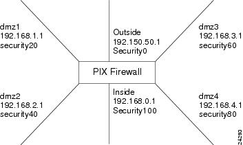
Figure 2-1
Sketching Interfaces and Security Levels
Step 3
•
•
•
•
•
Instead of specifying "0 0," to let all hosts start connections, you can specify a host or a network address and mask.
For example, to let only host 192.168.2.42 start connections on the dmz2 interface, you could specify:
nat (dmz2) 1 192.168.2.42 255.255.255.255The "1" after the interface specifier is the NAT ID. You can use one ID for all interfaces and the PIX Firewall sorts out which nat command statement pertains to which global command statement on which interface, or you can specify a unique NAT ID to limit access to specific interface. Remember that the nat command opens access to all lower security level interfaces so that if you want users on the inside to access the perimeter interfaces as well as the outside, then use one NAT ID for all interfaces. If you only want inside users to access the dmz1 interface but not the outside interface, use unique NAT IDs for each interface.
The NAT ID in the nat command must be the same NAT ID you use for the corresponding global command.
NAT ID 0 means to disable Network Address Translation.
Step 4
There must be enough global addresses to handle the number of users each interface may have trying to access the lower security interface. You can specify a single PAT (Port Address Translation) which permits up to 65,000 hosts to use a single IP address. PAT has some restrictions in its use such as it cannot support H.323 or caching nameserver use, so you may want to use it to augment a range of global addresses rather than using it as your sole global address.
For example:
global (outside) 1 192.150.50.9 netmask 255.255.255.0global (outside) 1 192.150.50.10-192.150.50.20 netmask 255.255.255.0The first global command statement specifies a single IP address, which the PIX Firewall interprets as a PAT. The PAT lets up to 65,535 hosts start connections to the outside. PIX Firewall permits one PAT global command statement for each interface The second global command statement augments the pool of global addresses on the outside interface. The PAT creates a pool of addresses used only when the addresses in the second global command statement are in use. This minimizes the exposure of the PAT in the event users need to use H.323 applications.
global (dmz1) 1 192.168.1.10-192.168.1.100 netmask 255.255.255.0global (dmz2) 1 192.168.2.10-192.168.2.100 netmask 255.255.255.0The global command statement for dmz1 lets users on the inside and dmz2 start connections on the dmz1 interface.
The global command statement for dmz2 lets users on the inside start connections on the dmz2 interface.
If you use network subnetting, specify the subnet mask with the netmask option. Refer to Appendix D, "" for more information on subnetting.
Step 7 - Create a Default Route
Use the route command to set a default route to the outside router. Use the show route command to view the command you entered. If needed, use the no route command to remove a route command. If the outside router is at address 192.150.50.3, you would use this command:
route outside 0 0 192.150.50.2 1This command states that the default router is on the outside interface. The 0 0 information is an IP address of 0.0.0.0 and mask of 0.0.0.0, which the PIX Firewall associates with the default route. The route command could be read as "if I have a packet intended for IP address 0.0.0.0, send it to 192.150.50.2 instead." The "1" at the end is the number of hops that the router is from the PIX Firewall. Hops are routers, so 1 hop is the router nearest the PIX Firewall.
If the PIX Firewall has only two interfaces, you can specify a default route for the inside. Note that this exception only applies when the PIX Firewall has physically two interfaces. If a third interface is present in the firewall without a cable connection, you have to physically remove the card before you can use this exception. If there are only two interfaces, the default route command for the inside will eliminate having to add static route command statements for the networks connected to the inside router (if any).
Note
Step 8 - Permit Ping Access
Enter the conduit permit icmp any any command in your configuration. This lets hosts on the inside ping outside hosts and hosts on the outside ping global addresses configured with the conduit command.
Step 9 - Store the Image in Flash Memory and Reboot
When you complete entering commands in the configuration, save it to Flash memory with the write memory command.
Then use the reload command to restart the configuration. After you enter the reload command, PIX Firewall prompts you to confirm that you want to continue. Enter y and the reboot occurs.
You are now done configuring the PIX Firewall. This configuration lets protected network users start connections, but prevents users on unprotected networks from attacking protected hosts.
Step 10 - Check the Configuration
Use the write terminal command to view your current configuration. Check the following before proceeding to ensure that your configuration is correct:
Step 1
Step 2
show ip addressshow globalshow natshow routeStep 3
route outside 0 0 ip_address_of_outside_router 1Replace ip_address_of_outside_router with the IP address of the nearest router on the outside interface.
If you do not see this command in your configuration, add it now. A default route command is crucial to get other commands to work correctly. If you are testing the network before putting it into production, get a router and add it to the test network so that the PIX Firewall has a default route.
Step 4
nat (dmz) 1 0 0global (outside) 1 192.150.50.2 netmask 255.255.255.0The number 1 after the interface name is the NAT ID.
Also, it is best to keep all the nat command statements and global command statements in the same NAT ID even if the global command statements refer to different interfaces, for example:
nat (inside) 1 0 0nat (dmz1) 1 0 0nat (dmz2) 1 0 0global (outside) 1 192.150.50.2 netmask 255.255.255.0global (outside) 1 192.150.50.10-192.150.50.200 netmask 255.255.255.0global (dmz1) 1 192.168.1.20-192.168.1.200 netmask 255.255.255.0The nat command statements let users on the inside, dmz1, and dmz2 interfaces start outside connections. The first global command statement creates a PAT address on the outside interface. The second global command statement creates a pool of IP addresses in the range of 192.150.50.30 to 192.150.50.200 on the outside interface.
The third global command statement creates a pool of IP addresses on the dmz1 interface. You can have one PAT global command statement per interface.
Step 5
Step 6
Step 7
Also make sure that the global pool contains correctly subnetted network addresses and broadcast addresses as explained in "." For example, with the 255.255.255.224 mask, specifying a global pool of 192.150.50.64-192.150.50.95 would not work because 192.150.50.64 is a network address and 192.150.50.95 is a broadcast address.
(a)
(b)
ip address outside 192.150.50.1 255.255.255.192The global command would appear as:
global (outside) 1 192.150.50.75-192.150.50.126 netmask 255.255.255.192Step 8
nat (dmz1) 1 10.0.0.0 255.0.0.0If you want only users on the 10.0.0.0 network to start connections, do not specify a second nat group with address 10.1.1.0 because this network would be included in 10.0.0.0.
Step 9
Make sure all inside interface or perimeter interface hosts and routers have their default routes set to the respective PIX Firewall interface IP address. Refer to section "Step 3 - Configure Network Routing" for more information.
Step 11 - Test Network Connectivity
For the steps that follow, you will need access to the PIX Firewall console and to at least one host on both the internal and external networks.
Use the steps that follow to determine whether or not the firewall is functioning correctly in the network:
Step 1
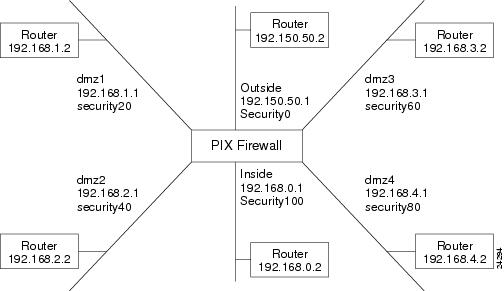
Figure 2-2
Sketch a Network with Interfaces and Routers
Step 2
Before using the debug command, use the who command to see if there are any Telnet sessions to the console. If the debug command finds a Telnet session, it automatically sends the debug output to the Telnet session instead of the console. This will cause the serial console session to seem as though no output is appearing when it is really going to the Telnet session.
Step 3
ping inside 192.168.0.2ping dmz1 192.168.1.2ping dmz2 192.168.2.2ping dmz3 192.168.3.2ping dmz4 192.168.4.2ping outside 192.150.50.2Then ping the PIX Firewall interfaces from the hosts or routers with commands such as:
•
•
•
•
•
•
If the pings from the hosts or routers to the PIX Firewall interfaces are not successful, check the debug messages which should have displayed on the console. Successful ping debug messages appear as in this example:
ICMP echo request (len 32 id 1 seq 512) 192.150.50.42 > 192.150.50.1ICMP echo reply (len 32 id 1 seq 256) 192.150.50.1 > 192.150.50.42Both the request and reply statements should appear to show that the PIX Firewall and the host responded. If none of these messages appeared while pinging the interfaces, then there is a routing problem between the host or router and the PIX Firewall that caused the ping (ICMP) packets to never arrive at the PIX Firewall.
Also try the following to fix unsuccessful pings:
(a)
route outside 0 0 192.150.50.2 1(b)
(c)
(d)
(e)
(f)
Ping through the PIX Firewall—Once you can ping the PIX Firewall's inside interface, try pinging through the PIX Firewall to a host on another interface, such as the outside. If there is not a host on the interface, ping the router. If the ping is not successful, check the debug messages on the PIX Firewall console to be sure both inbound and outbound pings were received. If you see the Inbound message without the Outbound, then the host or router is not responding. Check that the nat and global command statements are correct and that the host or router is on the same subnet as the outside interface. Successful ping debug messages appear as in this example:
Inbound ICMP echo reply (len 32 id 1 seq 256) 192.150.50.1 > 192.150.50.42Outbound ICMP echo request (len 32 id 1 seq 512) 192.150.50.42 > 192.150.50.1Step 4
Step 12 - Add Telnet Console Access
The serial console lets a single user configure the PIX Firewall, but many times this is not convenient for a site with more than one administrator. PIX Firewall lets you access the serial console via Telnet from hosts on any internal interface.
With PIX Firewall version 5.0 and IPSec configured, you can use Telnet to remotely administer the console of a PIX Firewall from the outside interface.
To configure Telnet console access:
Step 1
telnet 192.168.1.2 255.255.255.255 insideIf IPSec is in place, you can let a host on the outside interface access the PIX Firewall console. Use a command such as:
telnet 209.165.200.225 255.255.255.224 outsideThe telnet command does not have an interface identifier. The PIX Firewall compares the IP address you specify in the telnet command to those in the ip address command statements to ensure that the address you specify is on an internal interface (any interface except the outside interface).
Step 2
telnet timeout 15Step 3
Step 4
To test Telnet access:
Step 1
telnet 192.168.1.1Step 2
PIX passwd:Enter cisco and press the Enter key. You are then logged into the PIX Firewall.
The default password is cisco, which you can change with the passwd command.
You can enter any command on the Telnet console that you can set from the serial console, but if you reboot the PIX Firewall, you will need to log back into the PIX Firewall after it restarts.
Some Telnet applications such as the Windows 95 or Windows NT Telnet sessions may not support access to the PIX Firewall's command history feature used with the arrow keys. However, you can access the last entered commands by pressing Ctrl-P.
Step 3
Messages for a successful ping appear as:
Inbound ICMP echo reply (len 32 id 1 seq 256) 192.150.50.1 > 192.150.50.42Outbound ICMP echo request (len 32 id 1 seq 512) 192.150.50.42 > 192.150.50.1Step 4
(a)
If you are using the PIX Firewall in production mode, you may wish to use the logging buffered 7 command to store messages in a buffer that you can view with the show logging command, and clear the buffer for easier viewing with the clear logging command. To stop buffering messages, use the no logging buffered command.
You can also lower the number from 7 to a lesser value, such as 3, to limit the number of messages that appear.
(b)
Trace Channel Feature
The debug icmp trace and debug sqlnet commands send their output to the Trace Channel. The location of the Trace Channel depends on whether you have a simultaneous Telnet console session running at the same time as the console session, or if you are using only the PIX Firewall serial console:
•
•
•
•
The debug commands are shared between all Telnet and serial console sessions.
Note
Step 13 - Add Server Access
By default, the PIX Firewall prevents all outside connections from accessing "inside" hosts or servers. Any server on a network that has a higher security level than the current interface requires a static and conduit command statement.
Note
For example, to let outside users access a dmz1 web server, you could have static and conduit command statements as follows:
static (dmz1,outside) 192.150.50.5 192.168.1.5 netmask 255.255.255.255conduit permit tcp host 192.150.50.5 eq www anyIn this example, the static command maps access to the dmz1 host 192.168.1.5 through a global address on the outside interface of 192.150.50.5. The conduit command lets any users on the outside access IP address 192.150.50.5 using a web browser on port 80 (www). In this example, the higher security level interface is dmz1 and the lower is the outside interface. On the outside interface, through the use of DNS, a company can map 192.150.50.5 to their web site address of www.caguana.com.
To help you code server access, use this rule for creating static command statements:
static (high,low) low high
The idea is to present an IP address to users on one interface that gives them access to a host on another. You use the static command to let users on a lower security level interface access a server on a higher security level interface. You use the nat command to let users on a higher security level interface access a lower security level interface.
To create server access:
Step 1
Step 2
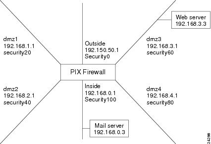
Figure 2-3 Sketch a Network Diagram with Servers
From this scenario, you will need static command statements to let outside users access the dmz3 web server and for dmz1 and dmz2 users to access the web server. You will need a nat command statement to let inside and dmz4 users access the dmz3 web server.
For the mail server, you will need static command statements for access from the outside, dmz1, and dmz2, dmz3, and dmz4 interfaces.
Step 3
static (inside,outside) 192.150.50.4 192.168.3.4 netmask 255.255.255.255conduit permit tcp host 192.150.50.4 eq smtp anyThese commands create a global address of 192.150.50.4 that PIX Firewall maps to the 192.168.3.4 mail server on the dmz2 interface. The conduit command statement permits any outside users to access the mail server at the SMTP port (25).
You will need to inform your DNS administrator to create an MX record for the global address (such as 192.150.50.4) so that mail is directed to the correct address.
We recommend that you not use the any keyword instead of specifying an IP address of a host that can access the static mapping in the conduit command statement. Using any lets any outside host access the static. In cases, such as for a server available for public access, using any is the only choice. However, if you can limit the number of users who have access to a server, you reduce the chance of intrusion.
PIX Firewall lets you specify a foreign IP address to protect access to the conduits. This is very important when there are multiple interfaces. If you set up a conduit command for the dmz2 interface to access the dmz1 interface, you would not want outside users to be able to access the conduit command. PIX Firewall handles this for you. It automatically determines which interfaces are mapped together with the static command statement.
Special Conduits
Two conduit command statements are required for establishing access to the following services: discard, dns, echo, ident, pptp, rpc, sunrpc, syslog, tacacs-ds, talk, and time. Each service, except for pptp, requires one conduit for TCP and one for UDP. For DNS, if you are only receiving zone updates, you only need a single conduit command statement for TCP.
The two conduit command statements for the PPTP transport protocol, which is a subset of the GRE protocol, are as shown in this example:
static (dmz2,outside) 192.150.50.5 192.168.1.5 netmask 255.255.255.255conduit permit tcp host 192.150.50.5 eq 1723 anyconduit permit gre host 192.150.50.5 anyIn this example, PPTP is being used to handle access to host 192.168.1.5 on the dmz2 interface from users on the outside. Outside users access the dmz2 host using global address 192.150.50.5. The first conduit command statement opens access for the PPTP protocol and gives access to any outside users. The second conduit permits access to GRE. If PPTP was not involved and GRE was, you could omit the first conduit command statement.
Step 4
•
static (inside,dmz1) 192.168.1.4 192.168.0.3 netmask 255.255.255.255conduit permit tcp host 192.168.1.4 eq smtp any•
static (inside,dmz2) 192.168.2.4 192.168.0.3 netmask 255.255.255.255conduit permit tcp host 192.168.2.4 eq smtp any•
static (inside,dmz3) 192.168.3.4 192.168.0.3 netmask 255.255.255.255conduit permit tcp host 192.168.3.4 eq smtp any•
static (inside,dmz2) 192.168.4.4 192.168.0.3 netmask 255.255.255.255conduit permit tcp host 192.168.4.4 eq smtp anyThese command statements create a global address on each interface to map to the inside mail server and then create a conduit so that users on each interface can access the mail server via the SMTP port (25).
Step 5
To let users access the web server:
Step 1
•
static (dmz3,outside) 192.150.50.3 192.168.3.3 netmask 255.255.255.255conduit permit tcp host 192.150.50.3 eq www any•
static (dmz3,dmz1) 192.168.1.3 192.168.3.3 netmask 255.255.255.255conduit permit tcp host 192.168.1.3 eq www any•
static (dmz3,dmz2) 192.168.2.3 192.168.3.3 netmask 255.255.255.255conduit permit tcp host 192.168.2.3 eq www any•
nat (dmz4) 1 192.168.4.0 255.255.255.0global (dmz3) 1 192.168.3.10-192.168.3.100 netmask 255.255.255.0•
nat (inside) 1 192.168.0.0 255.255.255.0The static and conduit command statements work the same way as described previously for the mail server, creating a global address through which users on the interface can access the web server. The global command adds a new dimension to server access. Because the inside interface is at a higher security level than the dmz2 interface, instead of using static and conduit command statements to permit access, you use nat and global command statements.
The nat command statement lets inside users start connections on any interface of a lower security level; therefore, they can access the dmz2 interface. The global command lets the inside users translate their connections to access the address of the web server on the dmz2 interface.
Step 2
Step 14 - Add Static Routes
Specify a static route for each network connected to any router. Refer to the section "Step 7 - Create a Default Route" for information on default routes, and to the section "Step 3 - Configure Network Routing" for information on configuring routers and hosts for default routes.
To add static routes:
Step 1
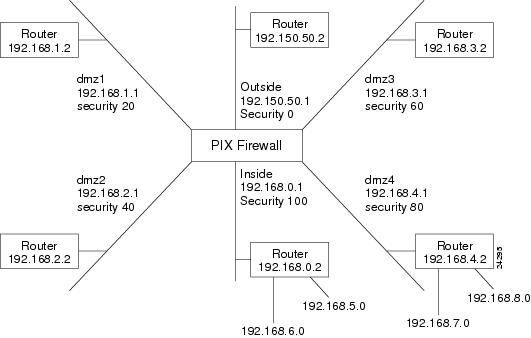
Figure 2-4 Sketch Network with Routes
Step 2
route outside 0 0 192.150.50.2 1This command statement sends all packets destined for the default route, IP address 0.0.0.0 (abbreviated as 0, and 0 for the netmask), to the router 192.150.50.2. The "1" at the end of the command statement indicates that the router is the router closest to the PIX Firewall; that is, one hop away.
In addition, you must add static routes for the networks that connect to the inside router as follows:
route inside 192.168.5.0 255.255.255.0 192.168.0.2 1route inside 192.168.6.0 255.255.255.0 192.168.0.2 1These static route command statements can be read as "for packets intended for either network 192.168.5.0 or 192.168.6.0, ship them to the router at 192.168.0.2." The router decides which packet goes to which network. The PIX Firewall is not a router and cannot make these decisions.
The "1" at the end of the command statement specifies how many hops (routers) the router is from the PIX Firewall. Because it is the first router, you use 1.
Step 3
route dmz4 192.168.7.0 255.255.255.0 192.168.4.2 1route dmz4 192.168.8.0 255.255.255.0 192.168.4.2 1These command statements direct packets intended to the 192.168.6.0 and 192.168.7.0 networks back through the router at 192.168.3.5.
Step 15 - Enable Syslog
The syslog message facility in the PIX Firewall is a useful means to view troubleshooting messages and to watch for network events such as attacks and service denials. You can view syslog messages either from the PIX Firewall console or from a syslog server that the PIX Firewall sends syslog messages to.
This section includes the following topics:
•
•
•
•
Viewing Messages from the Console
To view messages from the PIX Firewall console:
Step 1
Step 2
logging buffered debuggingThis command opens syslog up for all possible messages. The debugging setting is very useful for troubleshooting, but on a PIX Firewall in production, will generate too many messages to make troubleshooting viable. If you are testing a production mode PIX Firewall, substitute the errors keyword for the debugging keyword. This will reduce the messages to only those generated by logging levels 0, 1, 2, and 3. Refer to the System Log Messages for the Cisco Secure PIX Firewall Version 5.0 guide for information about which messages display at each syslog level.
Step 3
conduit permit icmp any anyIf this command is not present, then add it.
Step 4
Step 5
Step 6
logging buffered alertsThis command will only store messages of levels 0 and 1.
Viewing Messages from a Telnet Console Session
To view syslog messages on a Telnet console session:
Step 1
telnet 192.168.1.3 255.255.255.255 insideStep 2
Step 3
Step 4
Step 5
Step 6
Step 7
terminal no monitorno logging monitorThe information in the remainder of this section describes additional information on the logging command and how to configure PIX Firewall to send messages to a syslog server.
Sending Messages to a Syslog Server
PIX Firewall can send syslog messages to either the PIX Firewall Syslog Server (PFSS) or to another syslog server such as those in UNIX or other operating systems.
In the event that all syslog servers are offline, PIX Firewall stores up to 100 messages in its memory. Subsequent messages that arrive overwrite the buffer starting from the first line.
If you have a Windows NT system, use of the PFSS gives you the additional benefit of reliability through receiving TCP event messages, receiving time stamped messages, and being able to monitor whether the server is up or down from the PIX Firewall. The PFSS is available without cost from Cisco Connection Online (CCO). Installation instructions for the PFSS are provided in the Installation Guide for the Cisco Secure PIX Firewall Version 5.0.
Note
Unless you need the certainty that every syslog message sent must be stored on the PFSS, and you can afford the possible network downtime to free the Windows NT disk space, only use UDP logging. If you use TCP logging, ensure that PFSS log files are backed up regularly to minimize the possibility of running out of disk space.To send messages to a syslog server:
Step 1
logging host dmz1 192.168.1.5If you want to use the reliable syslog feature of the PFSS whereby the PIX Firewall stops its traffic if the PFSS Windows NT disk becomes full or the system is unavailable, use the tcp option; for example:
logging host interface address tcp/portReplace interface with the interface on which the server exists, address with the IP address of the host, and port with the TCP port (if different than the default value of 1468).
You can see if PIX Firewall traffic has been disabled due to a PFSS disk-full condition with the show logging command and look for the "disabled" keyword in the display.
Only one UDP or TCP command statement is permitted for a server. A subsequent command statement overrides the previous one. Use the write terminal command to view the logging host command statement in the configuration. In the configuration, the UDP protocol appears as "17" and TCP as "6."
Step 2
logging trap debuggingCisco recommends that you use the debugging level during initial setup and during testing. Thereafter, set the level from debugging to errors for production use.
Step 3
Step 4
Step 5
clock set 14:25:00 apr 1 2000logging timestampIn this example, the clock is set to the current time of 2:25 pm on April 1, 1999, and time stamping is enabled. To disable time-stamp logging, use the no logging timestamp command.
Step 6
http://www.cisco.com/univercd/cc/td/doc/product/iaabu/pix/pix_v50/index.htm
For example, to block the following message:
%PIX-6-305002: Translation built for gaddr IP_addr to IP_addrUse this command to stop the message from being sent to the syslog server:
no logging message 305002If you want to let the message resume being sent, use the following command:
logging message 305002You can view disabled messages with the following command:
show logging disabledno logging message 305002You can re-enable all previously blocked messages with the following command:
clear logging disabled
Note
Changing PFSS Parameters
You can change PFSS parameters at the Windows NT system using the Start>Settings>Control Panel>Services feature.
All PFSS parameter values can be viewed by examining the pfss.log file, which PFSS creates in the same directory as the PFSS log files.
The PFSS starts immediately after installation. You can use the Services control panel to enter new parameters, pause the service and then resume the service, or to stop and start the service. Choose one or more parameters from the following:
•
•
•
•
•
For example, to set %_disk_full to 35 percent and the disk-full timer to 10 seconds:
Step 1
Step 2
Step 3
Step 4
PFSS stores syslog messages in one of seven files: monday.log, tuesday.log, wednesday.log, thursday.log, friday.log, saturday.log, sunday.log (according to the day of the week). If a week has already passed since the last log file was created, it will rename the old log file to weekday.mmddyy where weekday is the current day, mm is the month, dd is the day, and yy is the year; for example, monday.103099.
Note
Recovering from Disk-full
If you have specified that the PIX Firewall send syslog messages via TCP, you may encounter the possibility that the Windows NT disk will become full and the PIX Firewall unit will stop its traffic. If the Windows NT file system is full, the Windows NT system beeps and the PFSS disables all TCP connections from the PIX Firewall unit(s) by closing its TCP listen socket.
The PIX Firewall tries to re-connect to the PFSS five times, and during the retry, it stops all new connections through the PIX Firewall. You then need to back up all the log files to another disk or across the network. (While PFSS is receiving messages, the log files must reside on the local disk.)
To recover from the disk-full condition:
Step 1
Step 2
Step 3
no logging host dmz1 10.1.1.2Step 4
logging host dmz1 10.1.1.2 tcp/1468Step 5
More on the logging Command
The logging facility and logging level commands configure the facility and level of syslog messages. Because network devices share the eight facilities, the logging facility command lets you set the facility marked on all messages. Messages are sent to the syslog host over UDP. The logging on command starts sending messages. Use the logging host command to specify which systems receive the messages.
You can us the show logging command to view previously sent messages.
The PIX Firewall generates syslog messages for system events, such as security alerts and resource depletion. Syslog messages may be used to create email alerts and log files, or displayed on the console of a designated host using UNIX syslog conventions.
A PC WinSock version of syslogd will also work.
The PIX Firewall sends syslog messages to document the following events:
•
•
•
•
Logging is enabled by configuring the PIX Firewall with the IP address of the log host.
Syslog Facility and Level
The logging facility and logging trap commands let you specify the syslog facility and level for how messages are sent to the syslog host.
The facility consists of eight facilities LOCAL0(16) through LOCAL7(23); the default is LOCAL4(20). Hosts file the messages based on the facility number in the message.
The level specifies the types of messages sent to the syslog host. Setting the level to 3, the default value, for example, allows messages with levels 0, 1, 2, and 3 to display. The default is 3.
Table 2-2 Syslog Message Levels
0
emergencies
System unusable messages
1
alerts
Take immediate action
2
critical
Critical condition
3
errors
Error message
4
warnings
Warning message
5
notification
Normal but significant condition
6
informational
Information message
7
debugging
Debug messages and log FTP commands and WWW URLs. For more information about logging FTP commands and URLs, refer to "FTP and URL Logging" in "."
Configuring a UNIX System for Syslog
After you have configured PIX Firewall to send syslog messages, configure either a PC or UNIX host to receive the messages. This section describes how to configure a UNIX host to receive syslog messages.
To configure a UNIX system to accept syslog messages:
Step 1
Step 2
# mkdir /var/log/pix# touch /var/log/pix/pixfirewallStep 3
# PIX Firewall syslog messageslocal4.error /var/log/pix/pixfirewallThis configuration directs the PIX Firewall syslog message to the specified file. Alternatively, if you want the message sent to the logging host console or emailed to a system administrator, refer to the UNIX syslog.conf(4) manual page.
Note
Entries in /etc/syslog.conf must follow these rules:
(a)
(b)
(c)
Step 4
# kill -1 `cat /etc/syslog.pid`This command lists the syslog process ID. This number may vary by system.
Step 16 - Create Access Lists
PIX Firewall provides the outbound and apply commands that you can use to limit internal users access to services on external interfaces. Use these commands to limit access for users who are on a higher security level interface from accessing a lower security level interface; for example, from the inside to the outside, from the inside to a perimeter interface, or between perimeter interfaces. These commands follow the direction of the nat command—also from a higher security level interface to a lower security level interface.
The outbound and apply commands' use is very interwoven. Depending on how you set the apply command, you use the outbound command to specify the details. The apply command lets you specify the interface you want to protect and how you are using the access list—to limit service access to your internal users (with the outgoing_src option, or to limit internal users access to a specific site (with the outgoing_dest option).
The outbound command specifies whether you are permitting or denying access, the affected IP addresses, and the port number or numbers. To coordinate the outbound and apply command statements, there is an identification number on both commands called the "list ID." The list ID is also used to order groups of commands so as to determine which group is processed first. This number is independent of the nat and global commands identification numbers—you can use the same number or another. Cisco recommends coding list IDs with gaps in the range to permit future additions, such as 10, 20, 30, or 100, 200, 300. Just be sure to use the same list ID on the apply command statement as on the outbound command for the same group. For example:
outbound 10 deny 0 0 www tcpoutbound 10 permit 192.168.1.2 255.255.255.255 www tcpapply (dmz1) 10 outgoing_srcIn addition, the order in which you specify the outbound commands determines how PIX Firewall evaluates them. The outbound command statements are ordered first by denies, then permits, and then by the list ID. Then there is the except option to this command, which has its own set of rules that are best viewed on the outbound / apply command page in "."
There are a few caveats with the outbound command. With the outgoing_src option to the apply command, you can only specify the internal hosts that are affected, not where you want them to go. Use the outgoing_src option to regulate access to services (ports) and protocols.
With the outgoing_dest option, you can only specify which host you do not want users to access, but not limit specific users access to the host. Use the outgoing_dest option to regulate access to a host.
Before creating an access list:
Step 1
Step 2
To limit users access to a service:
Step 1
outbound 10 deny 192.168.1.0 255.255.255.0 irc tcpStep 2
outbound 10 permit 192.168.1.42 255.255.255.255 irc tcpStep 3
apply (dmz1) 10 outgoing_srcTo limit users access to a host:
Step 1
outbound 20 deny 192.150.50.42 255.255.255.255 www tcpStep 2
apply (dmz1) 20 outgoing_destStep 17 - Add AAA User Authentication
User authentication and authorization starts with your security policy and the respective inside RADIUS or TACACS+ server that you have.
Authentication verifies that a user is who they say they are. Authorization determines what services a user can use to access a host.
From the configuration on this server you need to determine which users can access the network, which services they can use, and what hosts they can access. Once you have this information, you can configure the PIX Firewall to either enable or disable authentication or authorization.
In addition, you can also configure the firewall to permit users access to specific hosts or services. However, if you configure the firewall to this degree, you risk the information being different between the authentication server and the firewall. After you enable authentication and authorization, the PIX Firewall provides credential prompts to inbound or outbound users for FTP, Telnet, or HTTP (Web) access. The actual decision about who can access the system and with what services is handled by the authentication and authorization servers.
To provide user authentication and authorization:
Step 1
Step 2
Step 3
aaa-server AuthInbound protocol tacacs+aaa-server AuthInbound (inside) host 10.1.1.1 TheUauthKeyaaa-server AuthOutbound protocol radiusaaa-server AuthOutbound (inside) host 10.1.1.2 TheUauthKeyThe first command statement creates the AuthInbound authentication group using TACACS+ authentication. The second command statement states that the AuthInbound server is on the inside interface, that its IP address is 10.1.1.1, and the encryption key is "TheUauthKey."
The third command statement creates the AuthOutbound authentication group using RADIUS authentication. The fourth command statement states that the AuthOutbound server is on the inside interface, that its IP address is 10.1.1.2, and the encryption key is "TheUauthKey."
Step 4
aaa authentication any outbound 0 0 0 0 AuthOutboundaaa authentication any inbound 0 0 0 0 AuthInboundThe AuthInbound and AuthOutbound groups are those you specified with the aaa-server command.
Step 5
aaa authorization any outbound 0 0 0 0 AtacacsGroupaaa authorization any inbound 0 0 0 0 AuthInboundYou can specify port ranges for the aaa authorization command in the following format:
aaa authorization service|[protocol/port[-port]] outbound 0 0 0 0 group_tagwhere:
•
•
•
•
Step 18 - Recheck the Configuration
When you have completed your configuration, check it carefully as described in the following steps and tips:
Step 1
Step 2
Step 3
Step 4
(a)
(b)
(c)
(d)
(e)
(f)
Step 5
(a)
(b)
(c)
static (dmz2,dmz1) 10.1.1.2 192.168.1.2 netmask 255.255.255.255conduit permit tcp host 10.1.1.2 eq smtp 10.1.1.0 255.255.255.0In this example, the static command statement maps the 192.168.1.2 mail server on the dmz2 interface so that users on the dmz1 interface can access the server as 10.1.1.2. The conduit command statement specifies that only users on the 10.1.1.0 network can access the server via the SMTP port (25).
(d)
(e)
Step 6
Step 7
Step 8
Step 9
Step 10
Step 11
Additional tips to consider are as follows:
•
•
%PIX-3-305005: No translation group found for packet%PIX-3-305006: xlate_type translation creation failed for packetWhen the messages display, the contents of the packet displays as text. The xlate_type can be either static, portmapped, or regular. Portmapped refers to a PAT global.
•
•
•
•
•
•