Feedback
Table Of Contents
Failover Configuration Commands
Upgrading from PIX Firewall Version 4.2(1) to the Current Version
Upgrading from PIX Firewall Version 4.1 to Version 4.2
Frequently Asked Failover Questions
Compiling Cisco Syslog MIB Files
Private Link to IPSec Conversion
Private Link Versus IPSec Commands
Advanced Configurations
This chapter includes the following sections:
•
SNMP
•
Failover
Failover lets you add a secondary PIX Firewall unit that takes control if the Primary unit fails.
This section includes the following topics:
•
Understanding Failover
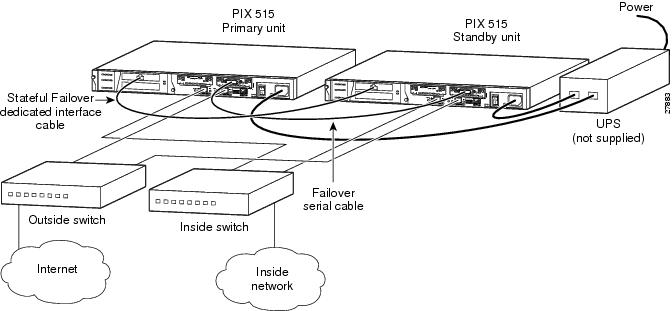
With version 5.0, you can choose the Stateful Failover option if you have 100 Mbps LAN interfaces so that connection states are automatically relayed between the two units.
Both units in a failover pair communicate through the failover cable, which is a modified RS-232 serial link cable that transfers data at 9600 baud. The data provides the unit identification of Primary or Secondary, the power status of the other unit, and serves as a communication link for various failover communications between the two units.
The two units send special failover "hello" packets to each other over all network interfaces and the failover cable every 15 seconds. The failover feature in PIX Firewall monitors failover communication, the power status of the other unit, and hello packets received at each interface. If two consecutive hello packets are not received within a time determined by the failover feature, failover starts testing the interfaces to determine which unit has failed, and transfers active control to the Standby unit.
When a failover occurs, each unit changes state. The newly Active unit assumes the IP and MAC addresses of the previously Active unit and begins accepting traffic. The new Standby unit assumes the failover IP and MAC addresses of the unit that was previously the Active unit. Because network devices see no change in these addresses, no ARP entries change or timeout anywhere on the network.
If you are using Stateful Failover, connection states are relayed from the Primary unit to the Secondary unit. Without Stateful Failover, the Standby unit does not maintain the state information of each connection. This means that all active connections will be dropped when failover occurs and that client systems must reestablish connections.
Stateful Failover
The Stateful Failover feature passes per-connection stateful information to the Standby unit. After a failover occurs, the same connection information is available at the new Active unit. End user applications are not required to do a reconnect to keep the same communication session. The state information passed to the Standby unit includes the global pool addresses and status, connection and translation information and status, the negotiated H.323 UDP ports, the port allocation bit map for PAT, and other details necessary to let the Standby unit take over processing if the Primary unit fails.
Depending on the failure, the PIX Firewall takes from 15 to 45 seconds to cause a switchover. Applications not handled by Stateful Failover will then require time to reconnect before the Active unit becomes fully functional.
Stateful Failover requires 100 Mbps Ethernet interface to be used exclusively for passing state information between the two PIX Firewall units. This interface can be connected to any of the following:
•
•
•
PIX Firewall does not support use of either Token Ring or FDDI for the Stateful Failover dedicated interface. Data is passed over the dedicated interface using IP protocol 105. No hosts or routers should be on this interface.
shows two PIX Firewall units connected for use with Stateful Failover.
Figure 3-1 Stateful Failover Minimum Setup
Stateful Failover Summary
The following provides a summary of Stateful Failover features, configuration, and restrictions:
1
(a)
•
•
•
•
•
(b)
•
•
•
•
(c)
•
•
•
•
•
2
(a)
(b)
(c)
(d)
•
•
•
•
3
(a)
(b)
4
Stateful Failover requires a feature-based license key with failover feature support or connection based license key.
5
failover onfailover ip address if_name ip_addressfailover link if_nameConfiguring Failover
This section includes the following topics:
•
Configuring Failover
To configure failover:
Step 1
Step 2
Step 3
Step 4
The sections that follow describe how to configure the Primary unit.
Configuration Replication
The two PIX Firewall units must be configured exactly the same and running the same software release. Configuration replication occurs over the failover cable from the Active unit to the Standby unit in three ways:
•
•
•
The configuration replication only occurs from memory to memory. After replication, use the write memory command to write the configuration into Flash memory. Because the failover cable is used, the replication can take a long time to complete with a large configuration. If a switchover occurs during the replication, the new Active unit will have a partial configuration. The unit will reboot itself to recover the configuration from the Flash or re-synchronize with the other unit. When the replication starts, the PIX Firewall console displays the message "Sync Started," and when complete, displays the message "Sync Completed." During the replication, information cannot be entered on the PIX Firewall console.
Failover Configuration Commands
Note
The following guidelines apply to configuring failover on the Active unit:
•
•
•
•
•
•
•
•
•
•
Use the show failover command to verify which unit is active and to provide Stateful Failover information.
If you want to force a PIX Firewall to be active or go to standby, you can use the failover active or no failover active command. Use this feature to force a PIX Firewall offline for maintenance or to return a failed unit to service.
Stateless TCP Failover
The failover timeout command lets you specify the length of time during which, if a failover occurs, the Standby unit lets connections started with the static command and the norandomseq option pass through the PIX Firewall without requiring a prior xlate to exist. This feature handles long-life connections during failover without requiring the connection to be reestablished.
The syntax for the failover command is:
failover timeout hh:mm:ss
If the hh:mm:ss is specified as -1, the length of time is indefinite.
AAA and user authentication connections are not supported by this feature.
When a stateless TCP connection is created, the following message is sent to syslog:
302009: Rebuilt TCP connection conn# for faddr foreign_ip/fport gaddr global_ip/gport
laddr local_ip/lport
Usage Notes
This section includes the following topics:
•
•
Usage Notes
The following notes apply to the use of failover on the PIX Firewall:
1
2
3
4
(a)
(b)
(c)
5
6
7
When this bridge loop is detected, the switch will stop forwarding packets for the duration of the forwarding delay time. It will then enter "listen" mode for an additional forward delay time during which time the switch is listening for bridge loops but still not forwarding traffic (and thus not forwarding failover hello packets). After twice the forward delay time (30 seconds) traffic should resume. The PIX Firewall will remain in "waiting" mode until it hears two hello packets (1 every 15 seconds for a total of 30 seconds). During this time the PIX Firewall passes traffic, and will not fail the unit if it does not hear the hello packets. All other failover monitoring is still occurring (power, interface, and failover cable hello).
8
9
10
show failoverFailover OffCable Status: My side not connectedReconnect timeout: 0:00:00Upgrading from PIX Firewall Version 4.2(1) to the Current Version
Step 1
Step 2
Step 3
(a)
(b)
(c)
Step 4
Step 5
Step 6
This completes the upgrade procedure.
Upgrading from PIX Firewall Version 4.1 to Version 4.2
Step 1
Note
Step 2
Step 3
Step 4
Step 5
Step 6
Step 7
Step 8
Step 9
Step 10
Step 11
Step 12
Step 13
Step 14
Step 15
This completes the upgrade procedure.
Failover Troubleshooting
This section includes the following topics:
•
After a Failover Occurs
If a failure is due to a condition other than a loss of power on the other unit, failover will begin a series of tests to determine which unit is failed. This series of tests will begin when hello messages are not heard for two consecutive 15-second intervals. Hello messages are sent over both network interfaces and the failover cable.
The purpose of these tests is to generate network traffic in order to determine which (if either) unit has failed. At the start of each test, each unit clears its received packet count for its interfaces. At the conclusion of each test, each unit looks to see if it has received any traffic. If it has, the interface is considered operational. If one unit receives traffic for a test and the other unit does not, the unit that received no traffic is considered failed. If neither unit has received traffic, then go to the next test.
Note
Use the following tests for failover:
•
•
•
•
Frequently Asked Failover Questions
This section contains some frequently asked questions about the failover feature. Additional questions relating to installation are provided in the Installation Guide for the Cisco Secure PIX Firewall Version 5.0.
•
A switch can be initiated by either unit. When a switch takes place, each unit changes state. The newly Active unit assumes the IP address and MAC address of the previously Active unit and begins accepting traffic for it. The new Standby unit assumes the IP address and MAC address of the unit that was previously the Standby unit.
•
When a unit boots up, it defaults to Failover Off and Secondary, unless the failover cable is present or failover has been saved in the configuration. The configuration from the Active unit is also copied to the Standby unit. If the cable is not present, the unit automatically becomes the Active unit. If the cable is present, the unit that has the primary end of the failover cable plugged into it becomes the Primary unit by default.
•
Commands entered on the Active unit are automatically replicated on the Standby unit.
•
When the Primary PIX Firewall unit experiences a power failure, the Standby PIX Firewall comes up in active mode. If the Primary unit is powered up again it will become the Standby unit.
•
Fault detection is based on the following:
•
•
•
•
•
•
•
•
Syslog messages will be generated when any errors or switches occur. Evaluate the failed unit and fix or replace it.
Failover Syslog Messages
Failover messages always have a syslog priority level of 2, which indicates a critical condition. Refer to the logging command description in "," for more information on syslog messages. Refer to the System Log Messages for the Cisco Secure PIX Firewall Version 5.0, available online. PIX Firewall documentation is available online at:
http://www.cisco.com/univercd/cc/td/doc/product/iaabu/pix/index.htm
To receive SNMP syslog traps (SNMP failover traps), you must configure the SNMP agent to send SNMP traps to SNMP management stations, define a syslog host, and also have compiled the Cisco syslog MIB into your SNMP management station. See the snmp-server and logging command pages in "," for more information.
ActiveX Blocking
ActiveX controls, formerly known as OLE or OCX controls, are components you can insert in a web page or other application. These controls include custom forms, calendars, or any of the extensive third-party forms for gathering or displaying information. As a technology, ActiveX creates many potential problems for the network clients including causing workstations to fail, introducing network security problems, or being used to attack servers.
The PIX Firewall ActiveX feature blocks the HTML <object> commands by commenting them out within the HTML web page. This functionality has been added to the filter command with the activex option.
Note
Note
WebSENSE URL Filtering
If your network has a WebSENSE server on any network interface, you can provide URL filtering through the PIX Firewall.
To configure the PIX Firewall to use WebSENSE:
Step 1
url-server (dmz) host 192.168.1.42 timeout 10In this example, the WebSENSE host is on the dmz interface at IP address 192.168.1.42. A timeout value of 10 seconds is specified as maximum allowed idle time before the PIX Firewall switches to the next WebSENSE server.
Step 2
filter url http 0 0 0 0 allow
Note
Step 3
FTP and URL Logging
This section includes the following topics:
Logging FTP and URL Messages
You can log FTP commands and WWW URLs when syslog is enabled. FTP and URL messages are logged at syslog level 7. As of version 5.0, usernames are provided in the log information.
Refer to the section "Step 15 - Enable Syslog" in "," for more information on how to view syslog messages on a server, console session, or via Telnet to the console.
Use the show fixup command to ensure that the fixup protocol commands for FTP and HTTP are present in the configuration:
fixup protocol http 80fixup protocol ftp 21These commands are in the default configuration.
The sections that follow provide sample output displays for each logging type.
Sample URL Log
The following is an example of a URL logging syslog message:
192.168.69.71 accessed URL 10.0.0.1/secrets.gifSample FTP Log
The following are examples of FTP logging syslog messages:
192.168.69.42 Retrieved 10.0.0.42:feathers.tar192.168.42.54 Stored 10.0.42.69:privacy.zipYou can view these messages at the PIX Firewall console with the show logging command.
SNMP
The snmp-server command causes the PIX Firewall to send SNMP traps so that the firewall can be monitored remotely. Use snmp-server host command to specify which systems receive the SNMP traps.
This section includes the following topics:
•
Introduction
The PIX Firewall SNMP MIB-II groups available are System and Interfaces.
All SNMP values are read only (RO).
Using SNMP, you can monitor system events on the PIX Firewall. SNMP events can be read, but information on the PIX Firewall cannot be changed with SNMP.
The PIX Firewall SNMP traps available to an SNMP management station are:
•
•
•
•
•
•
•
Use CiscoWorks for Windows (Product Number CWPC-2.0-WIN) or any other SNMP V1, MIB-II compliant browser to receive SNMP traps and browse a MIB. SNMP traps occur at UDP port 162.
MIB Support
Note
You can browse the System and Interface groups of MIB-II. Browsing a MIB is different from sending traps. Browsing means doing an snmpget or snmpwalk of the MIB tree from the management station to determine values.
SNMP Traps
Traps are different than browsing; they are unsolicited "comments" from the managed device to the management station for certain events, such as link up, link down, syslog event generated, and so on.
An SNMP object ID (OID) for PIX Firewall displays in SNMP event traps sent from the PIX Firewall. OID 1.3.6.1.4.1.9.1.227 was assigned as the PIX Firewall system object ID.
Two mechanisms work with SNMP, PIX Firewall responds to an SNMP request from a management state and the PIX Firewall sends a trap, which is an event notification. PIX Firewall supports two types of traps, generic and syslog traps.
The topics that follow include:
Receiving Requests
For the PIX Firewall to receive requests from an SNMP management station:
Step 1
Step 2
Sending Syslog Traps
To send traps from the PIX Firewall to an SNMP management station:
Step 1
If you only want to send the cold start, link up, and link down generic traps, no further configuration is required.
Step 2
Step 3
logging trap debuggingCisco recommends that you use the debugging level during initial set up and during testing. Thereafter, set the level from debugging to a lower value for production use.
Step 4
Step 5
Compiling Cisco Syslog MIB Files
To receive security and failover SNMP traps from the PIX Firewall, compile the Cisco SMI MIB and the Cisco syslog MIB into your SNMP management application. If you do not compile the Cisco syslog MIB into your application, you only receive MIB-II traps for link up or down, and firewall cold start.
You can get the Cisco MIB files on the Web from:
http://www.cisco.com/public/sw-center/netmgmt/cmtk/mibs.shtml
To compile Cisco syslog MIB files into your browser using CiscoWorks for Windows (SNMPc), complete the following steps:
Step 1
Step 2
Step 3
Step 4
Step 5
Step 6
Step 7
Step 8
Step 9
Step 10
Step 11
These instructions are only for SNMPc (CiscoWorks for Windows).
Private Link to IPSec Conversion
This section is intended for the Private Link users who are migrating from the PIX Firewall Private Link feature to the IPSec feature. It describes the main differences between the Private Link commands and the corresponding IPSec commands and provides a procedure on how to convert a Private Link configuration into an IPSec configuration using IKE to establish security associations.
Private Link is no longer supported in the PIX Firewall starting with version 5.0. It is supported in version 4. The Private Link feature allows Virtual Private Networks (VPNs) to be established between PIX Firewall sites connected to the same public (or outside) network. It enables incoming Private Link packets to bypass the NAT and ASA features and terminate on the inside interface. With the use of the sysopt ipsec pl-compatible command, the IPSec feature simulates the Private Link feature by allowing IPSec packets to also bypass the NAT and ASA features and terminate on the inside interface. See the sysopt command page for more information regarding the sysopt ipsec pl-compatible command.
Note
Basic Difference
While IPSec is a much larger feature set than Private Link, the two feature sets do not have a complete parent-child inheritance relationship. The main difference between Private Link and IPSec is that a Private Link tunnel begins on the receiving interface and ends on the sending interface while an IPSec tunnel begins on the sending interface and terminates on the receiving interface.
Private Link Versus IPSec Commands
outlines the mapping of the core Private Link commands with the corresponding IPSec commands. A description of each command follows.
For more information about the IPSec related commands listed in , see "," under the following command pages:
Link
The link command creates an encrypted path between Private Link-equipped PIX Firewall units. This command also enables Private Link to associate the shared private keys between the local host with a remote peer. In IPSec, the isakmp key command enables the local host to associate a shared key with a remote peer.
Note
The link command allows for the configuration of per packet authentication protection. In IPSec, the analogous protection is provided by the transform-set combination of ah-md5-hmac or esp-md5-hmac. You configure a transform set using the crypto ipsec transform-set command.
Linkpath
The linkpath command identifies the internal and external network interfaces on the remote peer running Private Link. The linkpath address selectors are used to select inbound traffic at the inside interface to encrypt and tunnel to the remote peer. In the reverse direction, the linkpath address selectors are used to decrypt outbound traffic, which originated from the remote peer, at the inside interface.
In IPSec, the access-list address selectors in the crypto map are used to select outbound traffic from the interface to encrypt and tunnel to the remote peer. In the reverse direction, the access-list address selectors are used to decrypt inbound traffic, which originated from the remote peer, at the outside interface.
The following are the steps to use to convert from a linkpath tunnel into an IPSec tunnel. These steps are included within the Private Link to IPSec configuration conversion procedure.
Step 1
Step 2
Step 3
Age
Private Link selects the next shared key in a "round-robin" method. The age command is used to define the number of minutes a current shared key is used before the rotation.
In IPSec, the crypto ipsec security-association lifetime second command is used to define how long the current shared key and the security association are used before their set time expires.
Conversion
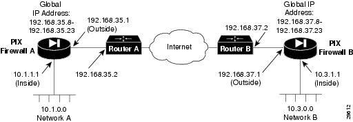
Covered in this section are the steps to convert your Private Link configuration into an IPSec configuration. An example of a Private Link configuration between two PIX Firewalls is provided for reference.
Figure 3-2 Example Private Link Network Diagram
shows the Private Link network diagram that corresponds to the following configurations.
On PIX Firewall A, the Private Link configuration is:
link 192.168.37.1 1 fadebacfadebaclink 192.168.37.1 2 bacfadefadebaclink 192.168.37.1 3 baabaaafadebaclink 192.168.37.1 4 beebeeefadebaclinkpath 10.3.0.0 255.255.255.0 192.168.37.1On PIX Firewall B, the Private Link configuration is:
link 192.168.35.1 1 fadebacfadebaclink 192.168.35.1 2 bacfadefadebaclink 192.168.35.1 3 baabaaafadebaclink 192.168.35.1 4 beebeeefadebaclinkpath 10.1.0.0 255.255.255.0 192.168.35.1In this configuration, the link command specifies 192.168.35.1 as the external network interface IP address of PIX Firewall B, and 192.168.37.1 as the external network interface IP address of PIX Firewall A. The key IDs are 1 through 4. The four keys to be shared between the two PIX firewall units are fadebacfadebac, bacfadefadebac, baabaaafadebac, and beebeeefadebac.
The linkpath command identifies the internal and external network interfaces belonging to the remote peer. So on the PIX Firewall A, PIX Firewall B's internal network interface IP address of 10.3.0.0 with a netmask of 255.255.255.0 and its external network interface IP address of 192.168.37.1 is set. On PIX Firewall B, PIX Firewall A's internal network interface IP address of 10.1.0.0 with a netmask of 255.255.255.0 and its external network interface IP address of 192.168.35.1 is set.
To convert your Private Link configuration into an IPSec configuration where IKE is used to establish security associations, perform the following steps. Perform your configuration on each PIX Firewall:
Step 1
PIX Firewall A:
sysopt ipsec pl-compatiblePIX Firewall B:
sysopt ipsec pl-compatibleStep 2
PIX Firewall A:
: connected routesroute inside 10.1.0.0 255.255.0.0 10.1.1.1route outside 192.168.35.0 255.255.255.0 192.168.35.1: nat routesroute inside 192.168.35.8 255.255.255.248 10.1.1.1route inside 192.168.35.16 255.255.255.248 10.1.1.1: reachability routesroute outside 10.3.0.0 255.255.0.0 192.168.35.2route outside 192.168.37.0 255.255.255.0 192.168.35.2route outside 0 0 192.168.35.2PIX Firewall B:
: connected routesroute inside 10.3.0.0 255.255.0.0 10.3.1.1route outside 192.168.37.0 255.255.255.0 192.168.37.1: nat routesroute inside 192.168.37.8 255.255.255.268 10.3.1.1route inside 192.168.37.16 255.255.255.268 10.3.1.1: reachability routesroute outside 10.1.0.0 255.255.0.0 192.168.37.2route outside 192.168.35.0 255.255.255.0 192.168.37.2route outside 0 0 192.168.37.2Step 3
PIX Firewall A:
isakmp policy 10 authentication pre-sharePIX Firewall B:
isakmp policy 10 authentication pre-shareStep 4
PIX Firewall A:
isakmp key fadebacfadebac address 192.168.37.1PIX Firewall B:
isakmp key fadebacfadebac address 192.168.35.1Step 5
PIX Firewall A:
crypto map Firewall-A 10 ipsec-isakmpPIX Firewall B:
crypto map Firewall-B 10 ipsec-isakmpStep 6
PIX Firewall A:
crypto map Firewall-A interface outsidePIX Firewall B:
crypto map Firewall-B interface outsideStep 7
PIX Firewall A:
access-list linkpath-aclA permit ip any 10.3.0.0 255.255.255.0PIX Firewall B:
access-list linkpath-aclB permit ip any 10.1.0.0 255.255.255.0Step 8
PIX Firewall A:
crypto map Firewall-A 10 match address linkpath-aclAPIX Firewall B:
crypto map Firewall-B 10 match address linkpath-aclBStep 9
PIX Firewall A:
crypto ipsec transform-set private-link-base esp-des ah-md5-hmacPIX Firewall B:
crypto ipsec transform-set private-link-base esp-des ah-md5-hmacStep 10
PIX Firewall A:
crypto map Firewall-A 10 set transform-set private-link-basePIX Firewall B:
crypto map Firewall-B 10 set transform-set private-link-baseStep 11
PIX Firewall A:
crypto map Firewall-A 10 set peer 192.168.37.1PIX Firewall B:
crypto map Firewall-B 10 set peer 192.168.35.1Step 12
PIX Firewall A:
crypto map Firewall-A interface outsidePIX Firewall B:
crypto map Firewall-B interface outside