Installing the Cisco ASA 5585-X
This chapter describes how to ground the chassis and install the cables. It contains the following sections:
Installation Sequence
Follow this sequence when installing the ASA 5585-X:
1.![]() Review the preparation directions and safety instructions in Preparing for Installation.
Review the preparation directions and safety instructions in Preparing for Installation.
2.![]() Place the ASA 5585-X on a flat, stable surface, or in a rack. Rack mounting instructions are provided in Installing and Removing a Slide-mounted Chassis.
Place the ASA 5585-X on a flat, stable surface, or in a rack. Rack mounting instructions are provided in Installing and Removing a Slide-mounted Chassis.
3.![]() Establish the system ground; see the next section, Establishing the System Ground.
Establish the system ground; see the next section, Establishing the System Ground.
4.![]() Connect interface cables to the ASA 5585-X, as described in Connecting Cables to the ASA 5585-X.
Connect interface cables to the ASA 5585-X, as described in Connecting Cables to the ASA 5585-X.
Establishing the System Ground
This section describes how to connect the system ground to the ASA 5585-X, and contains the following sections:
Requirements

Note![]() The system ground is also referred to as the network-equipment building system-ground.
The system ground is also referred to as the network-equipment building system-ground.

The system ground provides additional grounding for EMI shielding requirements and grounding for the low-voltage supplies (DC to DC converters). You must observe the following system-grounding guidelines for your chassis:
- You must install the system ground connection with any other rack or system power ground connections that you make.
- You must connect both the system ground connection and the DC power-supply ground connection to an earth ground.
- For an ASA5585-X that is equipped with DC-input power supplies, you must install the system ground before you attach the source DC power cables to the DC terminal block. If the ASA5585-X is powered on, you must power it off before attaching the system ground. If you are installing the system ground on an ASA5585-X that is equipped with an AC-input power supplies, you do not need to power off the chassis.
Note![]() In all situations, grounding practices must comply with Section 250 of the National Electric Code (NEC) requirements, or local laws and regulations. A 6 AWG grounding wire is preferred from the chassis to the rack ground, or directly to the common bonding network (CBN). The equipment rack should also be connected to the CBN with 6 AWG grounding wire.
In all situations, grounding practices must comply with Section 250 of the National Electric Code (NEC) requirements, or local laws and regulations. A 6 AWG grounding wire is preferred from the chassis to the rack ground, or directly to the common bonding network (CBN). The equipment rack should also be connected to the CBN with 6 AWG grounding wire.
Required Tools and Equipment
To connect the system ground, you will need the following tools and materials:
- Grounding lug—A two-hole standard barrel lug that supports up to 6 AWG wire (supplied as part of the system grounding accessory kit).
- Grounding screws—Two M4 x 8 mm pan-head screws (supplied as part of the system grounding accessory kit).
- Grounding wire—Should be sized according to local and national installation requirements. Depending on the power supply and system, a 12 AWG to 6 AWG copper conductor is required for U.S. installations. Commercially available 6 AWG wire is recommended. The length of the grounding wire depends on the proximity of the switch to proper grounding facilities (not supplied as part of the system grounding accessory kit).
- Number 1 Phillips screwdriver.
- Wire-stripping tool to remove the insulation from the grounding wire.
- Crimping tool to crimp the grounding wire to the grounding lug.
Connecting the System Ground
To attach the grounding lug and cable to the grounding pad, follow these steps:
Step 1![]() Use a wire-stripping tool to remove approximately 0.75 inch (19 mm) of the covering from the end of the grounding wire.
Use a wire-stripping tool to remove approximately 0.75 inch (19 mm) of the covering from the end of the grounding wire.
Step 2![]() Insert the stripped end of the grounding wire into the open end of the grounding lug.
Insert the stripped end of the grounding wire into the open end of the grounding lug.
Step 3![]() Crimp the grounding wire in the barrel of the grounding lug and verify that the ground wire is securely attached to the ground lug.
Crimp the grounding wire in the barrel of the grounding lug and verify that the ground wire is securely attached to the ground lug.
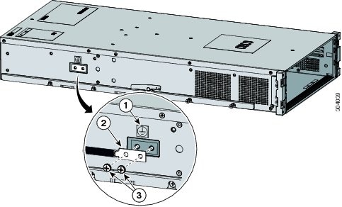
Step 4![]() Locate and remove the adhesive label from the system grounding pad on the back of the chassis. The location of the system grounding pad is on the left-rear side of the ASA5585-X chassis (Figure 3-1).
Locate and remove the adhesive label from the system grounding pad on the back of the chassis. The location of the system grounding pad is on the left-rear side of the ASA5585-X chassis (Figure 3-1).
Step 5![]() Place the grounding wire lug against the grounding pad, making sure that there is solid metal-to-metal contact.
Place the grounding wire lug against the grounding pad, making sure that there is solid metal-to-metal contact.
Note![]() The grounding lug rotates 180 degrees so that you can have the cable coming through the front or the back of the chassis.
The grounding lug rotates 180 degrees so that you can have the cable coming through the front or the back of the chassis.
Step 6![]() Secure the grounding lug to the chassis with two M4 screws (Figure 3-1). Make sure that the grounding lug and the grounding wire do not interfere with other hardware or rack equipment.
Secure the grounding lug to the chassis with two M4 screws (Figure 3-1). Make sure that the grounding lug and the grounding wire do not interfere with other hardware or rack equipment.
Figure 3-1 Attaching the Grounding Lug to the Chassis
|
|
|
||
|
|
|
Step 7![]() Prepare the other end of the grounding wire, and connect it to an appropriate grounding point in your site to ensure adequate earth ground for the switch.
Prepare the other end of the grounding wire, and connect it to an appropriate grounding point in your site to ensure adequate earth ground for the switch.
ASA 5585-X Cables
The ASA 5585-X supports use of the following cables:
- For the Ethernet ports, you can use either straight-through or cross-over twisted-pair cables since all RJ-45 Ethernet ports support MDI/MDIX.
Note![]() Auto-MDI/MDIX refers to the ability of the PHY associated with a given port to sense and automatically switch (if required) the transmit and receive signaling across a twisted-pair RJ-45 cable, thereby eliminating the need for special (for example, cross-over) cables based on the connecting port.
Auto-MDI/MDIX refers to the ability of the PHY associated with a given port to sense and automatically switch (if required) the transmit and receive signaling across a twisted-pair RJ-45 cable, thereby eliminating the need for special (for example, cross-over) cables based on the connecting port.
- The management port is a 10/100/1000-Mbps Ethernet port with an RJ-45 connector. You can use a modular, RJ-45, straight-through UTP cable to connect the management port to an external hub, switch, or router. You also can use cross-over twisted-pair cables since the ports also support MDI/MDIX.
- The console and auxiliary ports are serial ports and require the use of a flat rollover cable for terminal server connectivity (and a DB9 connector for connection to a PC).
- The ASA 5585-X supports 10/100/1000 BaseT Ethernet ports. You must use at least a Category 5RJ-45 RJ-45 cable for 100/1000Base-TX operations. You can use a Category 3 cable for RJ-45 10 Base-TX operations.
Connecting Cables to the ASA 5585-X
The ASA 5585-X has two dedicated Gigabit Ethernet interfaces for device management that are called Management 0/0 and Management 0/1. The management interfaces are similar to the console port, because they only accept traffic that is destined to-the-box (versus traffic that is through-the-box).
If you install an add-on SSP, you can connect a cable to the SSP’s Management 1/0 port to have remote management and monitoring of the SSP. It is not required, but if you do not connect to the Management 1/0 port, you will have to session into the SSP from the ASA 5585-X to gain access to it. Without directly connecting to the SSP, you cannot manage or monitor it over the network.
Depending on your configuration, you can configure any interface to be a management-only interface using the management-only command. You can also disable management-only configuration mode on the management interface. For more information about this command, see the management-only command in the Cisco ASA 5580 Adaptive Security Appliance Command Reference.
To connect the ASA 5585-X cables to the network interfaces, follow these steps:
Step 1![]() Connect to the management interface, Management 0/0.
Connect to the management interface, Management 0/0.
a.![]() Locate an Ethernet cable which has an RJ-45 connector on each end.
Locate an Ethernet cable which has an RJ-45 connector on each end.
b.![]() Connect one RJ-45 connector to the Management 0/0 interface.
Connect one RJ-45 connector to the Management 0/0 interface.
c.![]() Connect the other end of the Ethernet cable to the Ethernet port on your computer, or to your management network.
Connect the other end of the Ethernet cable to the Ethernet port on your computer, or to your management network.
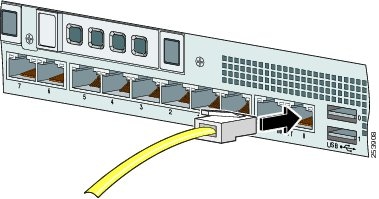
Step 2![]() (Optional) Connect to the SSP console port if you want to connect to a computer to enter configuration commands.
(Optional) Connect to the SSP console port if you want to connect to a computer to enter configuration commands.
a.![]() Before connecting a computer or terminal to any ports, determine the baud rate of the serial port. The baud rate of the computer or terminal must match the default baud rate (9600 baud) of the console port of the SSP.
Before connecting a computer or terminal to any ports, determine the baud rate of the serial port. The baud rate of the computer or terminal must match the default baud rate (9600 baud) of the console port of the SSP.
Set up the terminal as follows: 9600 baud (default), 8 data bits, no parity, 1 stop bits, and Flow Control (FC) = Hardware.
Note![]() The console port settings are the same for all SSPs.
The console port settings are the same for all SSPs.
b.![]() Connect the RJ-45 to the console port and connect the other end to your computer.
Connect the RJ-45 to the console port and connect the other end to your computer.
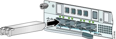
Step 3![]() (Optional) Connect to the SFP/SFP+ port(s) if you are using fiber-optic cables.
(Optional) Connect to the SFP/SFP+ port(s) if you are using fiber-optic cables.
The ASA 5585-X SSP-10 and SSP-20 have two SFP/SFP+ ports. The ASA 5585-X SSP-40 and SSP-60 have four SFP/SFP+ ports.
If you are using the fiber ports, you need an SFP+ transceiver module for 10-Gigabit Ethernet (a license may be required), or an SFP transceiver module for 1-Gigabit Ethernet (SFP and SFP+ transceiver modules are not included).
a.![]() Install a SFP/SFP+ transceiver module.
Install a SFP/SFP+ transceiver module.
b.![]() Connect one end of the LC cable to the SFP/SFP+.
Connect one end of the LC cable to the SFP/SFP+.
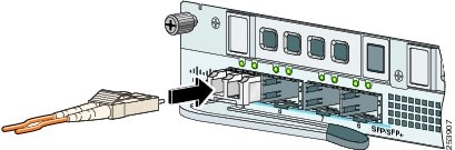
c.![]() Connect the other end of the LC cable to a network device, such as a router or switch.
Connect the other end of the LC cable to a network device, such as a router or switch.
Step 4![]() Install the electrical cables.
Install the electrical cables.
a.![]() Attach the power cable to the power supply module on the back of the ASA 5585-X.
Attach the power cable to the power supply module on the back of the ASA 5585-X.
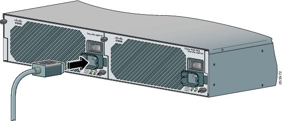
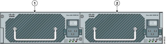
b.![]() If you have redundant power supply modules, you must connect both power cables to the back of the ASA 5585-X.
If you have redundant power supply modules, you must connect both power cables to the back of the ASA 5585-X.
|
|
|
c.![]() Plug the power cable(s) in to a power source (we recommend a UPS).
Plug the power cable(s) in to a power source (we recommend a UPS).
Step 5![]() Power on the ASA 5585-X.
Power on the ASA 5585-X.
Step 6![]() Check the PWR indicator on the front panel of the ASA 5585-X to verify interface connectivity. It should be green. To verify power supply operation, check the PS0 and PS1 indicators on the front panel. They should be green. On the back panel of the ASA 5585-X, make sure the IN OK and the FAN OK indicators are green and the OUT FAIL indicator is off.
Check the PWR indicator on the front panel of the ASA 5585-X to verify interface connectivity. It should be green. To verify power supply operation, check the PS0 and PS1 indicators on the front panel. They should be green. On the back panel of the ASA 5585-X, make sure the IN OK and the FAN OK indicators are green and the OUT FAIL indicator is off.
 Feedback