Installing and Connecting the ASA 5500-X
This chapter describes how to rack-mount the ASA and connect the interface cables.
Rack Mount the Chassis
The ASA 5512-X, 5515-X, and 5525-X chassis ship with rack mount brackets installed on the front of the chassis. 5545-X and 5555-X chassis ship with the slide rail mounting system.
- Rack Mount Guidelines
- Rack Mount the ASA 5512-X, 5515-X, and 5525-X With Brackets
- Rack Mount the ASA 5500-X Chassis with Slide Rail Mounting System
Rack Mount Guidelines
Warning![]() : To prevent bodily injury when mounting or servicing this unit in a rack, you must take special precautions to ensure that the system remains stable. The following guidelines are provided to ensure your safety: This unit should be mounted at the bottom of the rack if it is the only unit in the rack.When mounting this unit in a partially filled rack, load the rack from the bottom to the top with the heaviest component at the bottom of the rack.If the rack is provided with stabilizing devices, install the stabilizers before mounting or servicing the unit in the rack. Statement 1006
: To prevent bodily injury when mounting or servicing this unit in a rack, you must take special precautions to ensure that the system remains stable. The following guidelines are provided to ensure your safety: This unit should be mounted at the bottom of the rack if it is the only unit in the rack.When mounting this unit in a partially filled rack, load the rack from the bottom to the top with the heaviest component at the bottom of the rack.If the rack is provided with stabilizing devices, install the stabilizers before mounting or servicing the unit in the rack. Statement 1006
The following information can help plan equipment rack installation:
- Allow clearance around the rack for maintenance.
- If the rack contains stabilizing devices, install the stabilizers prior to mounting or servicing the unit in the rack.
- When mounting a device in an enclosed rack, ensure adequate ventilation. Do not overcrowd an enclosed rack. Make sure that the rack is not congested, because each unit generates heat.
- When mounting a device in an open rack, make sure that the rack frame does not block the intake or exhaust ports.
- If the rack contains only one unit, mount the unit at the bottom of the rack.
- If the rack is partially filled, load the rack from the bottom to the top, with the heaviest component at the bottom of the rack.
Rack Mount the ASA 5512-X, 5515-X, and 5525-X With Brackets
The ASA 5512-X, 5515-X, and 5525-X chassis ship with rack mount brackets installed on the front of the chassis. If you want to mount the chassis to the back of the rack, you can move the brackets from the front to the back of the chassis.
1.![]() (Optional) Move the brackets to the back of the chassis to install it in the back of the rack.
(Optional) Move the brackets to the back of the chassis to install it in the back of the rack.
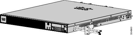
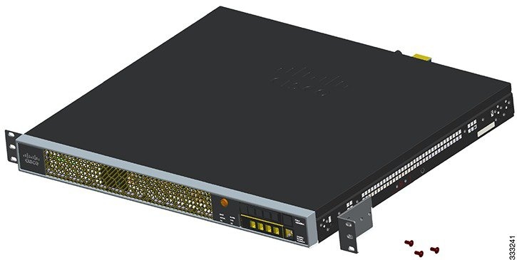
a.![]() Remove the rack-mount brackets from the chassis as shown in Figure 1.
Remove the rack-mount brackets from the chassis as shown in Figure 1.
Figure 1 Removing the Brackets from the Front of the Chassis
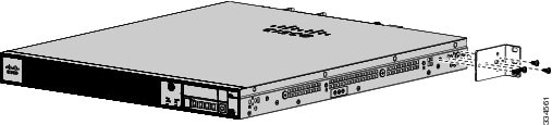
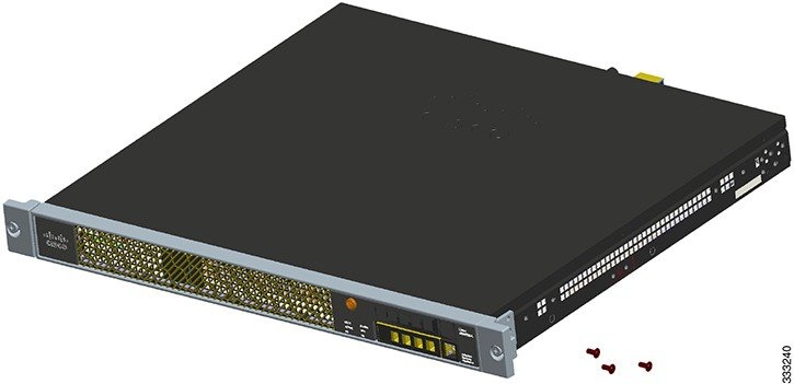
b.![]() Install the brackets on the back of the chassis by attaching the brackets to the holes in the chassis as shown in Figure 2. After the brackets are secured to the chassis, you can mount it in a rack.
Install the brackets on the back of the chassis by attaching the brackets to the holes in the chassis as shown in Figure 2. After the brackets are secured to the chassis, you can mount it in a rack.
Figure 2 Installing the Brackets on the Back of the Chassis
2.![]() We recommend that you install the chassis with the front bezel facing the cold aisle. (See Figure 3 for an example of air flow from front to back.)
We recommend that you install the chassis with the front bezel facing the cold aisle. (See Figure 3 for an example of air flow from front to back.)
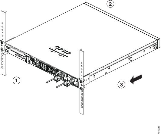
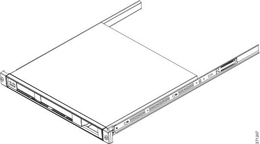
3.![]() Attach the chassis to the rack using the supplied screws appropriate for your rack (Figure 4).
Attach the chassis to the rack using the supplied screws appropriate for your rack (Figure 4).
Figure 4 Rack-Mounting the Chassis
Rack Mount the ASA 5500-X Chassis with Slide Rail Mounting System
The slide rail mounting system provides a quick, convenient, and secure method for rack mounting the chassis. While the 5545-X and 5555-X chassis ship with the slide rail mounting system and can be mounted using this system only, you can use the slide rail mounting system for any of the other ASA 5500-X series chassis, as well.
Prepare an ASA 5512-X, ASA 5515-X, or ASA 5525-X to Use a Slide Rail Rack Mount System
These instructions show how to prepare an ASA 5512-X, ASA 5515-X, or ASA 5525-X chassis for mounting with the slide rail rack mount system. These chassis models ship with preinstalled fixed rack-mount brackets, which must be replaced with the die-cast brackets that ship in the slide rail rack mount kit.
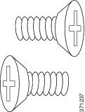
1.![]() From the slide rail rack mount kit, locate the two die-cast brackets, the six screws, and the four shoulder screws that you need to prepare your chassis for installation in the side rail rack.
From the slide rail rack mount kit, locate the two die-cast brackets, the six screws, and the four shoulder screws that you need to prepare your chassis for installation in the side rail rack.
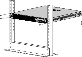
2.![]() Remove the preinstalled fixed rack-mount bracket on either side of the chassis by removing the three bracket screws that hold each bracket in place. (See Figure 5.)
Remove the preinstalled fixed rack-mount bracket on either side of the chassis by removing the three bracket screws that hold each bracket in place. (See Figure 5.)
Figure 5 Remove Preinstalled Screws and Brackets on Either Side of Chassis
3.![]() Install a die-cast bracket to either side of the chassis by aligning and inserting the tab at the end of the bracket into the hole on the chassis and then hinging it into position so that the bracket is flush with the front face plate (bezel) of the chassis. Secure each bracket to the chassis with three screws.
Install a die-cast bracket to either side of the chassis by aligning and inserting the tab at the end of the bracket into the hole on the chassis and then hinging it into position so that the bracket is flush with the front face plate (bezel) of the chassis. Secure each bracket to the chassis with three screws.
(See Figure 6.)
Figure 6 Install Die-Cast Brackets with Three Screws
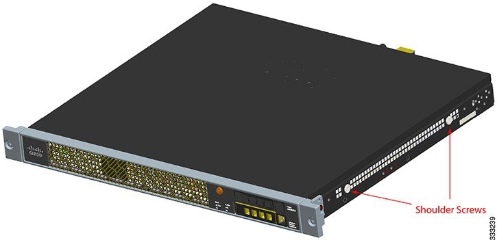
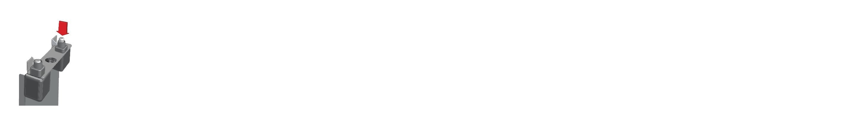
4.![]() Install two shoulder screws into the threaded hole locations on either side of the chassis (see Figure 7 for one side), and ensure that they are tight.
Install two shoulder screws into the threaded hole locations on either side of the chassis (see Figure 7 for one side), and ensure that they are tight.
Figure 7 Install Two Shoulder Screws on Either Side of the Chassis
Rack Mount the Chassis with the Slide Rail Mounting System
This section describes how to mount the chassis using the slide rail mounting system.
Although slide rail mounting is preferred, in the case of two-rail racks where the slide rails will not fit, you can use the rack mounting brackets. You must order them separately (ASA-BRACKETS=). Note that there will be a slight bend in the brackets when you attach them. For the procedure for attaching the brackets to the front or back of the chassis, see Rack Mount the ASA 5512-X, 5515-X, and 5525-X With Brackets.
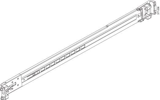
1.![]() Disassemble the slide rail.
Disassemble the slide rail.
a.![]() Extend the inner slide rail completely from the outer slide rail.
Extend the inner slide rail completely from the outer slide rail.
b.![]() Press the silver latch to retract the middle rail on the outer rail.
Press the silver latch to retract the middle rail on the outer rail.
c.![]() Repeat these steps for the other slide rail.
Repeat these steps for the other slide rail.
2.![]() Attach the inner rails to the chassis.
Attach the inner rails to the chassis.
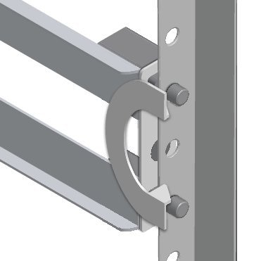
a.![]() Align one of the inner slide rail key holes over the chassis shoulder screw on one side. Slide the inner slide rail forward so that the shoulder screw is securely in place. Use a Phillips screwdriver to secure the inner slide rail with one Phillips screw (B).
Align one of the inner slide rail key holes over the chassis shoulder screw on one side. Slide the inner slide rail forward so that the shoulder screw is securely in place. Use a Phillips screwdriver to secure the inner slide rail with one Phillips screw (B).
b.![]() Secure the other inner slide rail to the chassis by repeating the previous steps on this page.
Secure the other inner slide rail to the chassis by repeating the previous steps on this page.
3.![]() (Round and Threaded Hole Racks Only) Customize the slide rails for round hole racks or threaded hole racks.
(Round and Threaded Hole Racks Only) Customize the slide rails for round hole racks or threaded hole racks.
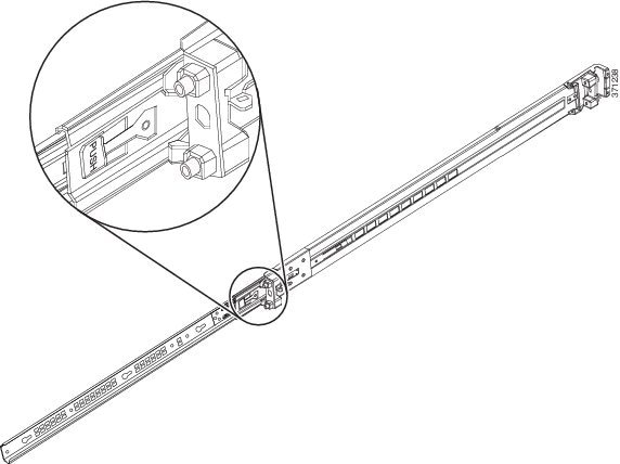
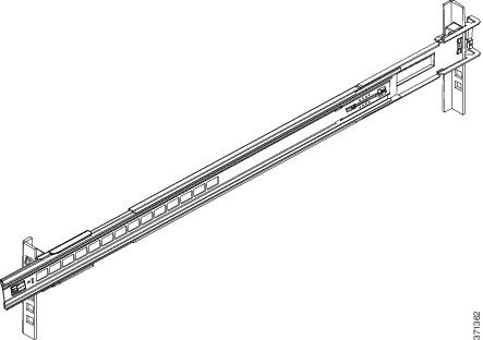
4.![]() Attach the outer slide rail to the rack.
Attach the outer slide rail to the rack.
a.![]() Align the front of the mounting pin on the outer slide rails with the rack upright, push it forward, and click it into place. Align the rear of the outer slide rail with the rack upright, pull the release tab, push the slide rail toward the rack, release the latch, and click it into place.
Align the front of the mounting pin on the outer slide rails with the rack upright, push it forward, and click it into place. Align the rear of the outer slide rail with the rack upright, pull the release tab, push the slide rail toward the rack, release the latch, and click it into place.
Note![]() : For racks shorter than 24 inches in depth, remove the rear bracket with a Phillips head screwdriver, pull the release tab, and adjust the slide rail to the appropriate length for the rack.
: For racks shorter than 24 inches in depth, remove the rear bracket with a Phillips head screwdriver, pull the release tab, and adjust the slide rail to the appropriate length for the rack.
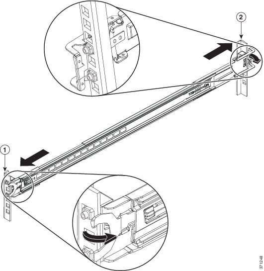
b.![]() Secure the other outer slide rail to the rack by repeating the previous step.
Secure the other outer slide rail to the rack by repeating the previous step.
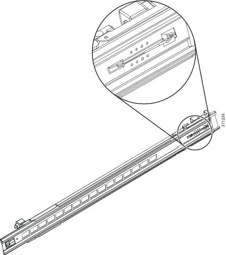
Note![]() : The previous illustration shows a square hole rack. If you are installing in a round hole rack, see the following illustration.
: The previous illustration shows a square hole rack. If you are installing in a round hole rack, see the following illustration.
The following illustration shows the casing pulled back on the inner peg. The rail can be installed in three different rack types.
The following illustration shows a rail installed in a threaded rail rack.
c.![]() Push both inner parts of the outer slide rails forward.
Push both inner parts of the outer slide rails forward.
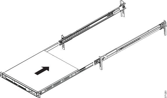
a.![]() Align the inner slide rails on the unit to the middle outer slide rails. Push the inner slide rails into the middle outer slide rails until they lock into place.
Align the inner slide rails on the unit to the middle outer slide rails. Push the inner slide rails into the middle outer slide rails until they lock into place.
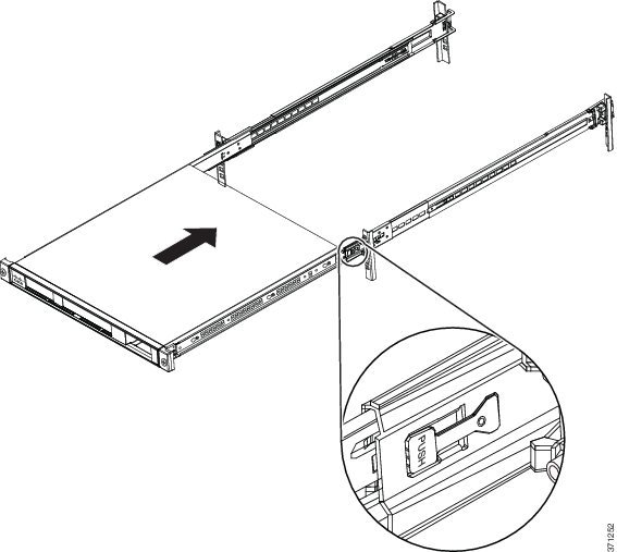
b.![]() Press the side release tabs to unlock the inner slide rail, and push the chassis into the rack.
Press the side release tabs to unlock the inner slide rail, and push the chassis into the rack.
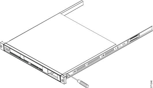
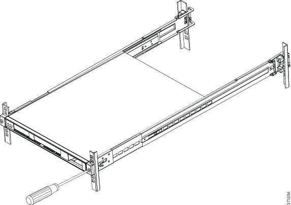
6.![]() Secure the chassis to the rack with the front captive screws.
Secure the chassis to the rack with the front captive screws.
Connecting Cables, Turning on Power, and Verifying Connectivity
This section describes how to connect the cables to the chassis and how to turn on the power.
Warning![]() : Only trained and qualified personnel should install, replace, or service this equipment. Statement 49
: Only trained and qualified personnel should install, replace, or service this equipment. Statement 49
Note![]() : Earlier ASAs (V01) require you to turn on the power with the power switch. Newer ASAs (V02) automatically turn on when you plug in the power cable. To determine your version, do one of the following:
: Earlier ASAs (V01) require you to turn on the power with the power switch. Newer ASAs (V02) automatically turn on when you plug in the power cable. To determine your version, do one of the following:
–![]() At the CLI prompt, enter the show inventory command and look for V01 or V02 in the output.
At the CLI prompt, enter the show inventory command and look for V01 or V02 in the output.
–![]() On the back of the chassis, look at the VID PID label for V01 or V02.
On the back of the chassis, look at the VID PID label for V01 or V02.
For the V01 chassis, see the following limitations:
–![]() The ASA requires 50 seconds from the time that AC power is applied before the power state can be updated and stored. This means that any changes to the power state within the first 50 seconds of applying AC power will not be observed if AC power is removed within that time.
The ASA requires 50 seconds from the time that AC power is applied before the power state can be updated and stored. This means that any changes to the power state within the first 50 seconds of applying AC power will not be observed if AC power is removed within that time.
–![]() The ASA requires 10 seconds from the time it is placed into standby mode before the power state can be updated and stored. This means any changes to the power state within the first 10 seconds of entering standby mode (including the standby mode itself) will not be observed if AC power is removed within that time.
The ASA requires 10 seconds from the time it is placed into standby mode before the power state can be updated and stored. This means any changes to the power state within the first 10 seconds of entering standby mode (including the standby mode itself) will not be observed if AC power is removed within that time.
For the V02 chassis, the above limitations to not apply.
Follow these steps to connect cables, turn on power, and verify connectivity.
1.![]() Place the chassis on a flat, stable surface, or in a rack (if you are rack-mounting it.)
Place the chassis on a flat, stable surface, or in a rack (if you are rack-mounting it.)
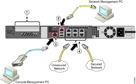
2.![]() Connect the interface cables.
Connect the interface cables.
|
|
(Optional) I/O Card. If you have a fiber-optic I/O card, you need to use SFP modules (not included). |
|
|
|
|
|
a.![]() Management 0/0 interface—For use with ASDM or CLI (with additional configuration). You can connect the management PC directly with an Ethernet cable, or connect the PC and the ASA to the same management network. Make sure the PC is configured to obtain an IP address using DHCP.
Management 0/0 interface—For use with ASDM or CLI (with additional configuration). You can connect the management PC directly with an Ethernet cable, or connect the PC and the ASA to the same management network. Make sure the PC is configured to obtain an IP address using DHCP.
Note![]() : You can configure any interface to be a management-only interface using the management-only command. You cannot disable management-only mode on the management interface.
: You can configure any interface to be a management-only interface using the management-only command. You cannot disable management-only mode on the management interface.
b.![]() (Optional) Console port—For use with the CLI. Connect the management PC or terminal server using the included serial console cable. The console cable has a DB-9 connector on one end for the serial port on your computer, and the other end is an RJ-45 connector. If your PC does not have a serial port, you will need to obtain a DB-9-to-USB serial adapter.
(Optional) Console port—For use with the CLI. Connect the management PC or terminal server using the included serial console cable. The console cable has a DB-9 connector on one end for the serial port on your computer, and the other end is an RJ-45 connector. If your PC does not have a serial port, you will need to obtain a DB-9-to-USB serial adapter.
c.![]() Gigabit Ethernet data interfaces—For data networks. For the installed network interfaces, use a standard RJ-45 Ethernet cable. For the optional I/O fiber-optic card, use SFP modules. See Install and Remove SFP Modules.
Gigabit Ethernet data interfaces—For data networks. For the installed network interfaces, use a standard RJ-45 Ethernet cable. For the optional I/O fiber-optic card, use SFP modules. See Install and Remove SFP Modules.
Note![]() : You can use any unused Gigabit Ethernet interface on the ASA as a failover link. The failover link interface is not configured as a normal networking interface; it should only be used for the failover link. You can connect the failover link by using a dedicated switch with no hosts or routers on the link, or by using an Ethernet cable to link the units directly.
: You can use any unused Gigabit Ethernet interface on the ASA as a failover link. The failover link interface is not configured as a normal networking interface; it should only be used for the failover link. You can connect the failover link by using a dedicated switch with no hosts or routers on the link, or by using an Ethernet cable to link the units directly.
3.![]() Connect the power cord to the ASA, and connect the other end to your power source.
Connect the power cord to the ASA, and connect the other end to your power source.
4.![]() For newer ASAs, the power turns on automatically when you plug in the power cable; do not press the power button on the front panel.
For newer ASAs, the power turns on automatically when you plug in the power cable; do not press the power button on the front panel.
For older ASAs, press the power button.
5.![]() Check the Power LED on the front of the ASA chassis. When it is solid green, the ASA is powered on.
Check the Power LED on the front of the ASA chassis. When it is solid green, the ASA is powered on.
6.![]() Check the Status LED on the front of the ASA chassis. When it is solid green, the ASA has passed power-on diagnostics.
Check the Status LED on the front of the ASA chassis. When it is solid green, the ASA has passed power-on diagnostics.
7.![]() See the Cisco ASA 5512-X, ASA 5515-X, ASA 5525-X, ASA 5545-X, and ASA 5555-X Quick Start Guide for further instructions on how to set up your device.
See the Cisco ASA 5512-X, ASA 5515-X, ASA 5525-X, ASA 5545-X, and ASA 5555-X Quick Start Guide for further instructions on how to set up your device.
Note![]() : Your ASA 5500-X ships with either ASA or Firepower Threat Defense software preinstalled. To reimage your device, see Reimage the Cisco ASA or Firepower Threat Defense Device.
: Your ASA 5500-X ships with either ASA or Firepower Threat Defense software preinstalled. To reimage your device, see Reimage the Cisco ASA or Firepower Threat Defense Device.
 Feedback