• How to implement CEM
  • Configuration Examples for CEM
  • Additional References

  • Configuring Circuit Emulation over Packet on Cisco IOS XR Software


    This module describes the configuration of Circuit Emulation over Packet (CEoP) shared port adapters (SPAs) on the Cisco XR 12000 Series Router.

    Feature History for Configuring CEoP on Cisco XR 12000 Series Router

    Release
    Modification

    Release 4.2.0

    Support for Circuit Emulation Service over Packet Switched Network was added in these SPAs:

    Cisco 1-port Channelized OC3/STM-1 Circuit Emulation and Channelized ATM SPA

    Cisco 2-Port Channelized T3/E3 Circuit Emulation and Channelized ATM SPA

    Cisco 24-Port Channelized T1/E1 Circuit Emulation and Channelized ATM SPA


    Contents

    Prerequisites for Configuration

    Overview of Circuit Emulation over Packet Service

    Information About Configuring CEoP Channelized SONET/SDH

    Clock Distribution

    Mode Change for CEoP SPA

    How to implement CEM

    Configuring Clocking

    Configuration Examples for CEM

    Additional References

    Prerequisites for Configuration

    You must be in a user group associated with a task group that includes the proper task IDs. The command reference guides include the task IDs required for each command. If you suspect user group assignment is preventing you from using a command, contact your AAA administrator for assistance.

    Before configuring the Circuit Emulation over Packet (CEoP) service on your router, ensure that these conditions are met:

    You must have one of these SPAs installed in your chassis:

    Cisco 1-port Channelized OC3/STM-1 Circuit Emulation and Channelized ATM SPA

    Cisco 2-Port Channelized T3/E3 Circuit Emulation and Channelized ATM SPA

    Cisco 24-Port Channelized T1/E1 Circuit Emulation and Channelized ATM SPA

    You should know how to apply and specify the SONET controller name and interface-path-id with the generalized notation rack/slot/module/port. The SONET controller name and interface-path-id are required with the controller sonet command.

    You should know how to apply and specify the T3/E3 and T1/E1 controller name and interface-path-id with the generalized notation rack/slot/module/port. The T3/E3, T1/E1 controller name and interface-path-id are required with the controller {T3|E3|T1|E1} command.

    Overview of Circuit Emulation over Packet Service

    Circuit Emulation over Packet (CEoP) is a way to carry TDM circuits over packet switched network. Circuit Emulation over Packet is the imitation of a physical connection. The goal of CEoP is to replace leased lines and legacy TDM networks. This feature allows network administrators to use their existing IP/MPLS network to provide leased-line emulation services or to carry data streams or protocols that do not meet the format requirements of other multiservice platform interfaces. CEoP puts TDM bits into the packets, encapsulates them into appropriate header and then sends through PSN. The receiver side of CEoP restores the TDM bit stream from packets.

    CEoP SPAs are half-height (HH) Shared Port Adapters (SPA) and the CEoP SPA family consists of 24xT1/E1/J1, 2xT3/E3, and 1xOC3/STM1 unstructured and structured (NxDS0) quarter rate, half height SPAs. The CEoP SPAs provide bit-transparent data transport that is completely protocol independent.

    CEoP has two major modes:

    Unstructured mode is called SAToP (Structure Agnostic TDM over Packet) — SAToP does not look what is inside the incoming data and considers it as a pure bit stream.

    Structured mode is named CESoPSN (Circuit Emulation Service over Packet Switched Network) — CESoPSN is aware of the structure of the incoming TDM bit stream at DS0 level.

    CESoPSN and SAToP can use MPLS, UDP/IP, and L2TPv3 for the underlying transport mechanism.


    Note The Cisco IOS XR Release 4.2.0 supports only MPLS transport mechanism.


    These SPAs are the first Cisco router interfaces designed to meet the emerging standards for Circuit Emulation Services over Packet Switched Network (CESoPSN) and Structure-Agnostic Transport over Packet (SAToP) transport.

    In Cisco IOS XR Release 4.2.0, the CEM functionality is supported on the following CEoP SPAs:

    Cisco 1-port Channelized OC3/STM-1 Circuit Emulation and Channelized ATM SPA

    Cisco 2-Port Channelized T3/E3 Circuit Emulation and Channelized ATM SPA

    Cisco 24-Port Channelized T1/E1 Circuit Emulation and Channelized ATM SPA

    In SAToP mode, these SPAs do not assume that data has any predefined format or structure. They simply regard the data as an arbitrary bit stream. All data bits are simply transported to a defined destination encapsulated in IP/MPLS packets. In CESoPSN mode the carrier has defined format. The SPAs support a full range of E1 and T1 framing. CESoPSN applications can save utilized bandwidth by selecting only valid timeslots for transmission. Some primary applications include:

    Transporting 2G and 3G network traffic over packet networks, for mobile operators. Mobile service providers are implementing high-speed data networks with HSDPA to support new revenue-generating services. The SPA is uniquely positioned for multigenerational migration of mobile networks (2G and 3G), simultaneously carrying TDM and ATM traffic over IP/MPLS networks. This technology provides a mechanism to enable IP/MPLS to the cell site, which can eventually be in place to transport the mobile traffic over IP from end to end.

    T3/E3 circuit emulation for leased-line replacement.

    T1/E1 circuit emulation for leased-line replacement.

    PBX to PBX connectivity over PSN.

    High density SS7 backhaul over IP/MPLS.

    Inter-MSC connectivity.

    Preencrypted data for government, defense, or other high-security applications.

    Proprietary synchronous or asynchronous data protocols used in transportation, utilities, and other industries.

    Leased-line emulation service offerings in metropolitan (metro) Ethernet or WAN service provider environments.

    For more information on Circuit Emulation service concepts, configuration, and example, see the Implementing MPLS Layer 2 VPNs module in the Cisco IOS XR Virtual Private Network Configuration Guide for the Cisco XR 12000 Series Router.

    Information About Configuring CEoP Channelized SONET/SDH

    To configure the Circuit Emulation over Packet Channelized SONET/SDH, you must understand the following concepts:

    Channelized SONET and SDH Overview

    Default Configuration Values for Channelized SONET/SDH

    Channelized SONET and SDH Overview

    Synchronous Optical Network (SONET) is an American National Standards Institute (ANSI) specification format used in transporting digital telecommunications services over optical fiber.

    Channelized SONET provides the ability to transport SONET frames across multiplexed T3/E3 and virtual tributary group (VTG) channels.

    The Cisco 1-port Channelized OC3/STM-1 Circuit Emulation and Channelized ATM SPA does not support the following modes:

    Clear Channel OC3

    Clear Channel E3

    Clear Channel T3

    SONET uses Synchronous Transport Signal (STS) framing. An STS is the electrical equivalent to an optical carrier 1 (OC-1).

    A channelized SONET interface is a composite of STS streams, which are maintained as independent frames with unique payload pointers. The frames are multiplexed before transmission.

    When a line is channelized, it is logically divided into smaller bandwidth channels called paths. These paths carry the SONET payload. The sum of the bandwidth on all paths cannot exceed the line bandwidth.

    When a line is not channelized, it is called clear channel, and the full bandwidth of the line is dedicated to a single channel that carries broadband services.

    Channelizing a SONET line consists of two primary processes:

    Configuring the controller

    Configuring the interface into channelized paths

    You configure the controller first by setting the mode of the STS path.

    When the mode is specified, the respective controller is created, and the remainder of the configuration is applied on that controller. For example, mode T3 creates a T3 controller. The T3 controller can then be configured to a serial channel, or it can be further channelized to carry T1s, and those T1s can be configured to serial interfaces.

    The Cisco 1-Port Channelized OC-3/STM-1 Circuit Emulation and Channelized ATM SPA does not support the following modes:

    Clear Channel OC3

    Clear Channel E3

    Clear Channel T3

    On a Cisco 1-Port Channelized OC-3/STM-1 SPA, the default configuration consists of the following paths that are already configured when the SONET card is installed.

    STS 1

    STS 2

    STS 3

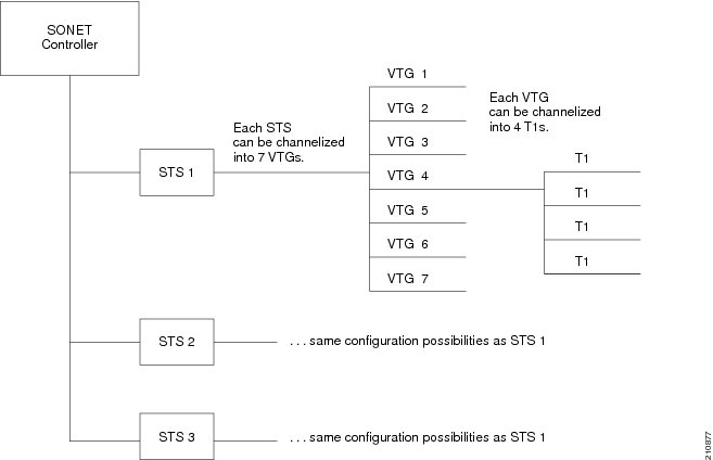
    Each STS path can be independently configured into T3s, E3s, or VTGs, and so on.

    Depending on the support for your installed SPA, each STS path can be independently configured into T3s, E3s, or VTGs, and so on.The following level of SONET channelization modes are supported in CEoP SPA:

    OC3->STS-1->VTG-> VT1.5 -> Unframed T1

    OC3->STS-1->VTG-> VT1.5 -> T1 -> DS0

    Figure 19 shows the VTG paths that can be configured.


    Note Only VTG paths are supported on the Cisco 1-Port Channelized OC-3/STM-1 SPA on the Cisco XR12000 Series Router.


    Figure 19 SONET VTG Channelized Paths
    Synchronous Digital Hierarchy (SDH) is the international equivalent of SONET.

    SDH uses Synchronous Transport Mode (STM) framing. An STM-1 is the electrical equivalent to 3 optical carrier 1s (OC-1s). A Synchronous Transport Module (STM) signal is the Synchronous Digital Hierarchy (SDH) equivalent of the SONET STS, but the numbers are different for each bandwidth. In this guide, the STM term refers to both path widths and optical line rates. The paths within an STM signals are called administrative units (AUs).

    A summary of the basic terminology differences between SONET and SDH is as follows:

    SONET STS is equivalent to SDH administrative unit (AU)

    SONET VT is equivalent to SDH tributary unit (TU)

    SDH basic building blocks are STM-1 (equivalent to STS-3) and STM-0 (equivalent to STS-1)

    An administrative unit (AU) is the information structure that provides adaptation between the higher-order path layer and the multiplex section layer. It consists of an information payload (the higher-order virtual container) and an administrative unit pointer, which indicates the offset of the payload frame start relative to the multiplex section frame start.

    An AU can be channelized into tributary units (TUs) and tributary unit groups (TUGs).

    An administrative unit 4 (AU-4) consists of three STM-1s or an STM-3.

    An administrative unit 3 (AU-3) consists of one STM-1.

    An administrative unit group (AUG) consists of one or more administrative units occupying fixed, defined positions in an STM payload.

    The Table 7 shows the commonly used notations and terms in SONET standards and their SDH equivalents.

    Table 7 SONET and SDH Terminology Equivalencies

    SONET Term
    SDH Term

    SONET

    SDH

    STS-3c

    AU-4

    STS-1

    AU-3

    VT

    TU

    SPE

    VC

    Section

    Regenerator Section

    Line

    Multiplex Section

    Path

    Path


    These are the levels of SDH channelization that are supported on the CEoP SPA:

    For E1 :

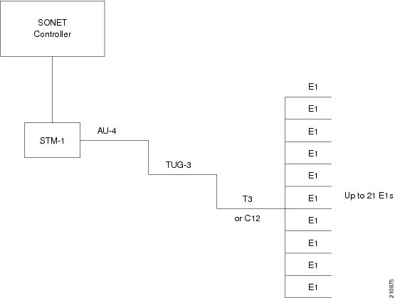
    STM1-> AU-4 -> TUG-3 -> TUG-2 ->VC12-> Unframed E1

    STM1-> AU-4 -> TUG-3 -> TUG-2 ->VC12-> E1 -> DS0

    For T1 :

    STM1-> AU-3-> TUG-2 -> VC11->Unframed T1

    STM1-> AU-3-> TUG-2 -> VC11->T1 -> DS0

    Figure 20 shows an example of SDH AU-3 paths that can be configured on the CEoP SPA.

    Figure 20 SDH AU3 Paths
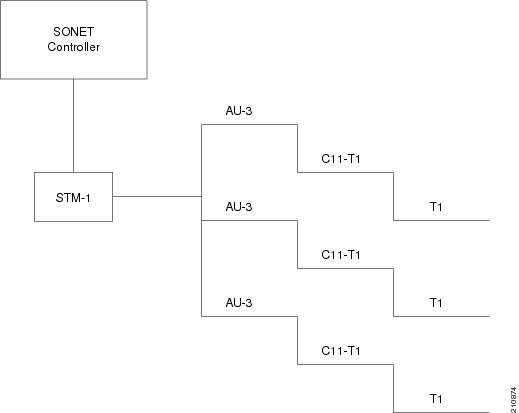
    Figure 21 shows the SDH AU4 paths that can be configured on the CEoP SPA.

    Figure 21 SDH AU4 Paths
    Default Configuration Values for Channelized SONET/SDH

    Table 8 describes the default configuration parameters that are present on the Channelized SONET/SDH.

    Table 8 SONET/SDH Controller Default Cit onfiguration Values

    Parameter
    Default Value
    Configuration File Entry

    Clock source

    line

    clock source {internal | line}

    SONET framing

    sonet

    hw-module sub-slot node-id cardtype {sonet | sdh}


    Clock Distribution

    Clocking distribution in the CEoP SPA can be done in these ways:

    Synchronous Clocking — With synchronous clocking, TDM lines on source and destination are synchronized to the same clock delivered by some means of physical clock distribution (SONET/SDH, BITS, GPS, and so on). The clock to the particular TDM line can be delivered from

    Line: the transmit clock is from the receiver of the same physical line

    Internal: the transmit clock is taken from line card and can be derived either from an internal free running oscillator or from another physical line

    Recovered: In-band pseudowire-based activeclock recovery on a CEM interface which is used to drive the transmit clock

    The number of recovered clocks that can be configured for CEoP SPA are:

    Cisco 24-Port Channelized T1/E1 Circuit Emulation and Channelized ATM SPA : 24 clocks for each SPA.

    Cisco 2-Port Channelized T3/E3 Circuit Emulation and Channelized ATM SPA : 10 clocks for each SPA in the T1/E1 mode and 2 clocks for each SPA in the T3/E3 mode.

    Cisco 1-port Channelized OC3/STM-1 Circuit Emulation and Channelized ATM SPA : 10 clocks per SPA in the T1/E1 mode.

    Adaptive Clocking — Adaptive clocking is used when the routers do not have a common clock source. See Figure 22. The clock is derived based on packet arrival rates. Two major types of adaptive clock recovery algorithms are:

    Based on dejitter buffer fill level

    Based on packet arrival rate

    The clock quality depends on packet size, has less tolerance to packet loss/corruption and introduces unnecessary delay in order to have sufficient number of packets in the buffer for clock recovery. The dejitter buffer size determines the ability of the emulated circuit to tolerate network jitter. The dejitter buffer in CEoP software is configurable up to a maximum of 500 milliseconds.


    Note The CEoP SPA hardware supports only the packet arrival rate algorithm.


    Figure 22 Adaptive Clock Recovery
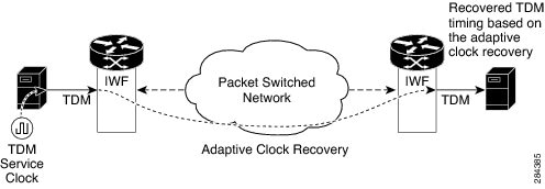

    Note CEM supports only adaptive clocking in the Cisco XR 12000 Series Router.


    For a sample CEM interface configuration, refer Circuit Emulation Interface Configuration: Examples.

    Mode Change for CEoP SPA

    This section explains about the command to change the mode of operation of CEoP SPA. At any specific instance, only one of this feature combination is possible on all the CEoP SPAs:

    Combination 1 : ATM + IMA + L3QoS

    Combination 2 : ATM + IMA + CEM

    The hw-module subslot nodeid mode CEM command is introduced in Cisco XR 12000 Series Router to configure the modes. The ATM + IMA + L3QoS is the default mode. These sections describe two scenarios for both the mode combinations.

    Host is configured and SPA is running in ATM + IMA + CEM mode

    When L3QoS is configured on an ATM / IMA interface and committed, the commit operation fails, as the mode is CEM mode.

    When the hw-module subslot nodeid mode CEM command is executed to switch the mode to ATM + IMA + L3QoS mode, with CEM configuration already present in running configuration, the commit fails with the message that CEM needs to be unconfigured before the change of mode to ATM + IMA + L3QoS. You must manually remove the CEM configuration before the SPA can be reloaded and booted in this new mode.

    Host is configured and SPA is running in ATM + IMA + L3QoS mode

    When CEM is configured and committed, the commit operation fails, as the mode is L3QoS mode.

    When the hw-module subslot nodeid mode CEM command is executed to switch the mode to ATM + IMA + CEM mode, with L3QoS configuration already present in running configuration, the commit fails with the message that L3QoS needs to be unconfigured before the change of mode to ATM + IMA + CEM. You must manually remove the L3QoS configuration before the SPA can be reloaded and booted in this new mode.

    The Table 9 shows the support for L3QoS functionality on the three CEoP SPAs.

    Table 9 Support for L3QoS functionality

    CEoP SPA Variant
    (ATM + IMA + CEM)
    (ATM + IMA + L3QoS)

    Cisco 24-Port Channelized T1/E1 Circuit Emulation and Channelized ATM SPA

    Yes

    Yes

    Cisco 2-Port Channelized T3/E3 Circuit Emulation and Channelized ATM SPA

    Yes

    Yes

    Cisco 1-port Channelized OC3/STM-1 Circuit Emulation and Channelized ATM SPA

    Yes

    No


    How to implement CEM

    This section contains the following procedures:

    Configuring SONET VT1.5-Mapped T1 Channels and Creating CEM Interface

    Configuring SDH AU-3 Mapped to C11-T1 or C12-E1

    Configuring the Cisco 24-Port Channelized T1/E1 Circuit Emulation and Channelized ATM SPA and Creating CEM Interface

    Configuring the Cisco 2-Port Channelized T3/E3 Circuit Emulation and Channelized ATM SPA and Creating CEM Interface

    Configuring CEM Interface

    Configuring Clocking

    Show Commands for CEM

    Configuring SONET VT1.5-Mapped T1 Channels and Creating CEM Interface

    In the case of Cisco 1-port Channelized OC3/STM-1 CEoP SPA, the STS stream can be channelized into the VT1.5 mapped T1 channel.

    This task explains how to configure a SONET line into VT-mapped T1 Channels.

    Prerequisites

    None.

    Restrictions

    Channelized SONET STS stream with VT1.5-T1 mapping is supported on the following SPA:

    Cisco 1-Port Channelized OC-3/STM-1 SPA

    SUMMARY STEPS

    1. configure

    2. hw-module subslot node-id cardtype type

    3. hw-module subslot node-id mode CEM

    4. commit

    5. controller sonet interface-path-id

    6. sts number

    7. mode mode

    8. root

    9. controller t1 interface-path-id

    10. cem-group unframed

    11. controller t1 interface-path-id

    12. cem-group framed group-number timeslots range1-range2

    13. no shutdown

    14. end
    or
    commit

    15. show runn interface cem interface-path-id

    DETAILED STEPS

     
    Command or Action
    Purpose

    Step 1 

    configure

    Example:

    RP/0/0/CPU0:router# configure

    Enters global configuration mode.

    Step 2 

    hw-module subslot node-id cardtype {sonet| sdh}

    Example:

    RP/0/0/CPU0:router(config-sonet)# hw-module subslot 0/3/0 sonet

    The hw-module subslot node-id cardtype type command configures the SPA to function in sonet/sdh mode.

    SONET framing (sonet) is the default. Whenever there is a change in framing mode (sonet/sdh), the SPA will be reloaded automatically. Reload will happen only when all the CEM Interface, T1 Controller and Sonet Controller configurations are removed completely. This is not applicable when you configure the first time because T1 controller and interface configurations would not exist.

    This configuration is mandatory for CEoP SPA to work normally in one of the framing modes. When you configure for the first time, it will not cause a SPA reload, if the cardtype is set to Sonet.

    Step 3 

    hw-module subslot node-id mode CEM

    Example:

    RP/0/0/CPU0:router(config-sonet)# hw-module subslot 0/3/0 mode CEM

    The hw-module subslot node-id mode CEM command configures the SPA to function in CEM mode.

    Step 4 

    commit

    Use the commit command to save the configuration changes to the running configuration file and remain within the configuration session.

    Step 5 

    controller sonet interface-path-id

    Enters controller configuration submode and specifies the SONET controller name and instance identifier with the rack/slot/module/port/controllerName notation.

    Step 6 

    sts number

    Example:

    RP/0/0/CPU0:router(config-sonet)# sts 1

    Configures the STS stream specified by number. The range is from1 to 3.

    Step 7 

    mode mode

    Example:

    RP/0/0/CPU0:router(config-stsPath)# mode t1

    Sets the mode of interface at the STS level. The possible modes are:

    vt15-t1—SONET path carrying virtual tributary 1.5 T1s (VT15 T1)

    Step 8 

    root
    
    Example:

    RP/0/0/CPU0:router(config-stsPath)# root

    Exits to global configuration mode. Go to step 7, if you want to create an structure agnostic CEM interface. Go to step 9, if you want to create a structure aware CEM interface.

    Step 9 

    controller t1 interface-path-id

    Example:

    RP/0/0/CPU0:router(config)# controller t1 0/0/1/0/1/4/1

    Enters T1 controller configuration submode and specifies the T1 controller name and interface-path-id with the rack/slot/module/port/sts-num/vtg-num/T1-num notation.

    Step 10 

    cem-group unframed

    Example:

    RP/0/0/CPU0:router(config)# cem-group unframed

    Creates an structure agnostic CEM interface.

    Step 11 

    controller t1 interface-path-id

    Example:

    RP/0/0/CPU0:router(config)# controller t1 0/0/1/0/1/5/1

    Enters T1 controller configuration submode and specifies the T1 controller name and interface-path-id with the rack/slot/module/port/sts-num/vtg-num/T1-num notation.

    Step 12 

    cem-group framed group-number timeslots range1-range2

    Example:

    RP/0/0/CPU0:router(config)# cem-group framed 0 timeslots 1

    Creates an structure aware CEM interface. The timeslots keyword specifies the time slots for the interface by range with the range1-range2 notation.

    Step 13 

    no shutdown

    Example:

    RP/0/0/CPU0:router(config-if)# no shutdown

    Removes the shutdown configuration.

    Note Removal of the shutdown configuration eliminates the forced administrative down on the interface, enabling it to move to an up or down state (assuming that the parent SONET layer is not configured administratively down).

    Step 14 

    end

    or

    commit

    Example:

    RP/0/00/CPU0:router(config-sonet)# end

    or

    RP/0/0/CPU0:router(config-sonet)# commit

    Saves configuration changes.

    When you issue the end command, the system prompts you to commit changes:

    Uncommitted changes found, commit them before 
    exiting(yes/no/cancel)? 
    
    [cancel]:


    Entering yes saves configuration changes to the running configuration file, exits the configuration session, and returns the router to EXEC mode.

    Entering no exits the configuration session and returns the router to EXEC mode without committing the configuration changes.

    Entering cancel leaves the router in the current configuration session without exiting or committing the configuration changes.

    Use the commit command to save the configuration changes to the running configuration file and remain within the configuration session.

    Step 15 

    show runn interface cem interface-path-id

    Example:

    RP/0/0/CPU0:router# show runn interface cem 0/0/2/0/1/1/1/1:1

    Verifies the CEM interface configuration.

    Configuring SDH AU-3 Mapped to C11-T1 or C12-E1

    This section includes the following tasks:

    Configuring SDH AU-3 Mapped to C11-T1 and Creating CEM Interface

    Configuring SDH AU-3 Mapped to C12-E1 and Creating CEM Interface

    Configuring SDH AU-3 Mapped to C11-T1 and Creating CEM Interface

    This task explains how to configure SDH AU-3 with c11-t1 mapping.

    Prerequisites

    You should know how to configure the SONET/SDH controller.

    Restrictions

    Channelized SDH AU-3 with c11-t1 mapping is supported on the following SPA:

    Cisco 1-Port Channelized OC-3/STM-1 SPA

    SUMMARY STEPS

    1. configure

    2. hw-module subslot node-id cardtype type

    3. hw-module subslot node-id mode CEM

    4. commit

    5. controller sonet interface-path-id

    6. au number

    7. mode mode

    8. root

    9. controller t1 interface-path-id

    10. cem-group unframed

    11. controller t1 interface-path-id

    12. cem-group framed group-number timeslots range1-range2

    13. no shutdown

    14. end
    or
    commit

    15. show runn interface cem interface-path-id

    DETAILED STEPS

     
    Command or Action
    Purpose

    Step 1 

    configure

    Example:

    RP/0/0/CPU0:router# configure

    Enters global configuration mode.

    Step 2 

    hw-module sub-slot node-id cardtype type

    Example:

    RP/0/0/CPU0:router(config-sonet)# hw-module sub-slot <> cardtype sdh

    Configures the controller for Synchronous Digital Hierarchy (SDH) framing. The hw-module subslot node-id cardtype type command configures the SPA to function in sonet/sdh mode.

    This command when committed results in automatic reload of SPA. Reload happens only when all the CEM interface, T1 Controller and Sonet Controller configurations are removed completely. This is not applicable when you configure the first time because T1 controller and interface configurations would not exist.

    This configuration is mandatory for CEoP SPA to work normally in one of the framing modes. SONET framing (sonet) is the default.

    Step 3 

    hw-module subslot node-id mode CEM

    Example:

    RP/0/0/CPU0:router(config-sonet)# hw-module subslot 0/3/0 mode CEM

    The hw-module subslot node-id mode CEM command configures the SPA to function in CEM mode.

    Step 4 

    commit

    Use the commit command to save the configuration changes to the running configuration file and remain within the configuration session.

    Step 5 

    controller sonet interface-path-id

    Enters controller configuration submode and specifies the SDH controller name and instance identifier with the rack/slot/module/port/controllerName notation.

    Step 6 

    au number

    Example:

    RP/0/0/CPU0:router(config-sonet)# au 1

    Specifies the administrative unit (AU) group and enters AU path configuration mode. For AU-3, the valid range is:

    1 to 3—1-Port Channelized OC-3/STM-1 SPA

    Note The au command does not specify the AU type. It specifies the number of the AU group for the AU type that you want to configure. The range for the AU command varies based on whether you are configuring AU-3 or AU-4.

    Step 7 

    mode mode

    Example:

    RP/0/0/CPU0:router(config-auPath)# mode c11-t1

    Sets the mode of interface at the AU level. AU-3 paths can be mapped to c11-t1 on supported SPAs.

    Step 8 

    root
    
    Example:

    RP/0/0/CPU0:router(config-auPath)# root

    Exits to global configuration mode.

    Step 9 

    controller t1 interface-path-id

    Example:

    RP/0/0/CPU0:router(config)# controller T1 0/0/2/0/1/1/4

    Enters T1 controller configuration submode and specifies the T1 controller name and interface-path-id with the rack/slot/module/port/auNum/t1Num notation.

    Step 10 

    cem-group unframed

    Example:

    RP/0/0/CPU0:router(config)# cem-group unframed

    Creates an structure agnostic CEM interface.

    Step 11 

    controller t1 interface-path-id

    Example:

    RP/0/0/CPU0:router(config)# controller t1 0/0/2/0/1/1/7

    Enters T1 controller configuration submode and specifies the T1 controller name and interface-path-id with the rack/slot/module/port/auNum/t1Num notation.

    Step 12 

    cem-group framed group-number timeslots range1-range2

    Example:

    RP/0/0/CPU0:router(config)# cem-group framed 1 timeslots 2-3

    Creates an structure aware CEM interface. The timeslots keyword specifies the time slots for the interface by range with the range1-range2 notation.

    Step 13 

    no shutdown

    Example:

    RP/0/0/CPU0:router(config-if)# no shutdown

    Removes the shutdown configuration.

    Note Removal of the shutdown configuration eliminates the forced administrative down on the interface, enabling it to move to an up or down state (assuming that the parent SONET layer is not configured administratively down).

    Step 14 

    end

    or

    commit

    Example:

    RP/0/0/CPU0:router(config-sonet)# end

    or

    RP/0/0/CPU0:router(config-sonet)# commit

    Saves configuration changes.

    When you issue the end command, the system prompts you to commit changes:

    Uncommitted changes found, commit them before 
    exiting(yes/no/cancel)? 
    
    [cancel]:


    Entering yes saves configuration changes to the running configuration file, exits the configuration session, and returns the router to EXEC mode.

    Entering no exits the configuration session and returns the router to EXEC mode without committing the configuration changes.

    Entering cancel leaves the router in the current configuration session without exiting or committing the configuration changes.

    Use the commit command to save the configuration changes to the running configuration file and remain within the configuration session.

    Step 15 

    show runn interface cem interface-path-id

    Example:

    RP/0/0/CPU0:router# show runn interface cem 0/0/2/0/1/1/1/1:1

    Verifies the CEM interface configuration.

    Configuring SDH AU-3 Mapped to C12-E1 and Creating CEM Interface

    This task explains how to configure SDH AU-3 with c12-e1 mapping.

    Prerequisites

    You should know how to configure the SONET/SDH controller.

    Restrictions

    Channelized SDH AU-3 with c12-e1 mapping is supported on the following SPAs:

    Cisco 1-Port Channelized OC-3/STM-1 SPA

    SUMMARY STEPS

    1. configure

    2. hw-module subslot node-id cardtype type

    3. hw-module subslot node-id mode CEM

    4. commit

    5. controller sonet interface-path-id

    6. au number

    7. mode tug3

    8. width number

    9. tug3 number

    10. mode mode

    11. root

    12. controller e1 interface-path-id

    13. cem-group unframed

    14. controller e1 interface-path-id

    15. cem-group framed group-number timeslots range1-range2

    16. no shutdown

    17. end
    or
    commit

    DETAILED STEPS

     
    Command or Action
    Purpose

    Step 1 

    configure

    Example:

    RP/0/0/CPU0:router# configure

    Enters global configuration mode.

    Step 2 

    hw-module sub-slot node-id cardtype type

    Example:

    RP/0/0/CPU0:router(config-sonet)# hw-module sub-slot <> cardtype sdh

    The hw-module subslot node-id cardtype type command configures the SPA to function in sonet/sdh mode. This command when committed results in automatic reload of SPA. Reload happens only when all the CEM interface, E1 Controller and Sonet Controller configurations are removed completely.

    Step 3 

    hw-module subslot node-id mode CEM

    Example:

    RP/0/0/CPU0:router(config-sonet)# hw-module subslot 0/3/0 mode CEM

    The hw-module subslot node-id mode CEM command configures the SPA to function in CEM mode.

    Step 4 

    commit

    Use the commit command to save the configuration changes to the running configuration file and remain within the configuration session.

    Step 5 

    controller sonet interface-path-id

    Enters controller configuration submode and specifies the SDH controller name and instance identifier with the rack/slot/module/port/controllerName notation.

    Step 6 

    au number

    Example:

    RP/0/0/CPU0:router(config-sonet)# au 1

    Specifies the administrative unit (AU) group and enters AU path configuration mode. For AU-3, the valid range is:

    1 to 3—1-Port Channelized OC-3/STM-1 SPA

    Note The au command does not specify the AU type. It specifies the number of the AU group for the AU type that you want to configure. The range for the AU command varies based on whether you are configuring AU-3 or AU-4.

    Step 7 

    mode tug3

    Example:

    RP/0/0/CPU0:router(config-auPath)# mode tug3

    Sets the mode of interface at the AU level. Currently only TUG3 is supported.

    Step 8 

    width number

    Example:

    RP/0/0/CPU0:router(config-auPath)# width 3

    Configures the number of the AU streams.

    Step 9 

    tug3 number

    Example:

    RP/0/0/CPU0:router(config-auPath)#tug3 1

    Specifies the Tributary Unit Group (TUG) number and enters the config-tug3Path mode. The range is 1 to 3.

    Step 10 

    mode mode

    Example:

    RP/0/0/CPU0:router(config-tug3Path)# mode c12-e1

    Sets the mode of interface at the tug3 level. The modes are:

    c12-e1—TUG-3 path carrying TU-12 to E1

    Step 11 

    root
    
    Example:

    RP/0/0/CPU0:router(config-auPath)# root

    Exits to global configuration mode.

    Step 12 

    controller e1 interface-path-id

    Example:

    RP/0/0/CPU0:router(config)# controller E1 0/0/2/0/1/1/1

    Enters E1 controller configuration submode and specifies the E1 controller name and interface-path-id with the rack/slot/module/port/auNum/tugNum/t1Num notation.

    Step 13 

    cem-group unframed

    Example:

    RP/0/0/CPU0:router(config)# cem-group unframed

    Creates an structure agnostic CEM interface.

    Step 14 

    controller e1 interface-path-id

    Example:

    RP/0/0/CPU0:router(config)# controller E1 0/0/2/0/1/1/7

    Enters E1 controller configuration submode and specifies the E1 controller name and interface-path-id with the rack/slot/module/port/auNum/tugNum/t1Num notation.

    Step 15 

    cem-group framed group-number timeslots range1-range2

    Example:

    RP/0/0/CPU0:router(config)# cem-group framed 0 timeslots 1

    Creates an structure aware CEM interface.

    Step 16 

    no shutdown

    Example:

    RP/0/0/CPU0:router(config-if)# no shutdown

    Removes the shutdown configuration.

    Note Removal of the shutdown configuration eliminates the forced administrative down on the interface, enabling it to move to an up or down state (assuming that the parent SONET layer is not configured administratively down).

    Step 17 

    end

    or

    commit

    Example:

    RP/0/0/CPU0:router(config-sonet)# end

    or

    RP/0/0/CPU0:router(config-sonet)# commit

    Saves configuration changes.

    When you issue the end command, the system prompts you to commit changes:

    Uncommitted changes found, commit them before 
    exiting(yes/no/cancel)? 
    
    [cancel]:


    Entering yes saves configuration changes to the running configuration file, exits the configuration session, and returns the router to EXEC mode.

    Entering no exits the configuration session and returns the router to EXEC mode without committing the configuration changes.

    Entering cancel leaves the router in the current configuration session without exiting or committing the configuration changes.

    Use the commit command to save the configuration changes to the running configuration file and remain within the configuration session.

    Configuring the Cisco 24-Port Channelized T1/E1 Circuit Emulation and Channelized ATM SPA and Creating CEM Interface

    This task explains how to configure the Cisco 24-Port Channelized T1/E1 Circuit Emulation and Channelized ATM SPA.

    SUMMARY STEPS

    1. configure

    2. hw-module subslot node-id cardtype type

    3. hw-module subslot node-id mode CEM

    4. commit

    5. controller t1 interface-path-id

    6. cem-group unframed

    7. controller t1 interface-path-id

    8. cem-group framed group-number timeslots range1-range2

    9. no shutdown

    10. end
    or
    commit

    11. show runn interface cem interface-path-id

    DETAILED STEPS

     
    Command or Action
    Purpose

    Step 1 

    configure

    Example:

    RP/0/0/CPU0:router# configure

    Enters global configuration mode.

    Step 2 

    hw-module subslot node-id cardtype {t1| e1}

    Example:

    RP/0/0/CPU0:router(config-t1)# hw-module subslot 0/3/0 cardtype t1

    The hw-module subslot node-id cardtype type command configures the SPA to function in t1/e1 mode.

    Reload will happen only when all the CEM interface, T1 Controller configurations are removed completely. This is not applicable when you configure the first time because T1 controller and interface configurations would not exist.

    Step 3 

    hw-module subslot node-id mode CEM

    Example:

    RP/0/0/CPU0:router(config-t1)# hw-module subslot 0/3/0 mode CEM

    The hw-module subslot node-id mode CEM command configures the SPA to function in CEM mode.

    Step 4 

    commit

    Use the commit command to save the configuration changes to the running configuration file and remain within the configuration session.

    Step 5 

    controller t1 interface-path-id

    Example:

    RP/0/0/CPU0:router(config)# controller t1 0/0/1/0/1

    Enters T1 controller configuration submode and specifies the T1 controller name and interface-path-id with the rack/slot/module/port/T1num notation.

    Step 6 

    cem-group unframed

    Example:

    RP/0/0/CPU0:router(config-t1)# cem-group unframed

    Creates an structure agnostic CEM interface.

    Step 7 

    controller t1 interface-path-id

    Example:

    RP/0/0/CPU0:router(config)# controller t1 0/0/1/0/1

    Enters T1 controller configuration submode and specifies the T1 controller name and interface-path-id with the rack/slot/module/port/T1num notation.

    Step 8 

    cem-group framed group-number timeslots range1-range2

    Example:

    RP/0/0/CPU0:router(config-t1)# cem-group framed 0 timeslots 1

    Creates an structure aware CEM interface. The timeslots keyword specifies the time slots for the interface by range with the range1-range2 notation.

    Step 9 

    no shutdown

    Example:

    RP/0/0/CPU0:router(config-if)# no shutdown

    Removes the shutdown configuration.

    Note Removal of the shutdown configuration eliminates the forced administrative down on the interface, enabling it to move to an up or down state.

    Step 10 

    end

    or

    commit

    Example:

    RP/0/0/CPU0:router(config-t1)# end

    or

    RP/0/0/CPU0:router(config-t1)# commit

    Saves configuration changes.

    When you issue the end command, the system prompts you to commit changes:

    Uncommitted changes found, commit them before 
    exiting(yes/no/cancel)? 
    
    [cancel]:


    Entering yes saves configuration changes to the running configuration file, exits the configuration session, and returns the router to EXEC mode.

    Entering no exits the configuration session and returns the router to EXEC mode without committing the configuration changes.

    Entering cancel leaves the router in the current configuration session without exiting or committing the configuration changes.

    Use the commit command to save the configuration changes to the running configuration file and remain within the configuration session.

    Step 11 

    show runn interface cem interface-path-id

    Example:

    RP/0/0/CPU0:router# show runn interface cem 0/0/2/0/1:1

    Verifies the CEM interface configuration.

    Configuring the Cisco 2-Port Channelized T3/E3 Circuit Emulation and Channelized ATM SPA and Creating CEM Interface

    T3/E3 Channelization Mode

    This task explains how to configure the Cisco 2-Port Channelized T3/E3 Circuit Emulation and Channelized ATM SPA using T3/E3 channelization.


    Note The T3/E3 channels can be channelized further into T1s or E1s, and the T1s or E1s can be channelized into time slots (DS0s), on the Cisco 2-Port Channelized T3/E3 Circuit Emulation and Channelized ATM SPA.


    SUMMARY STEPS

    1. configure

    2. hw-module subslot node-id cardtype type

    3. hw-module subslot node-id mode CEM

    4. commit

    5. controller {t3 | e3} interface-path-id

    6. cem-group unframed

    7. no shutdown

    8. end
    or
    commit

    9. show runn interface cem interface-path-id

    DETAILED STEPS

     
    Command or Action
    Purpose

    Step 1 

    configure

    Example:

    RP/0/0/CPU0:router# configure

    Enters global configuration mode.

    Step 2 

    hw-module subslot node-id cardtype {t3| e3}

    Example:

    RP/0/0/CPU0:router(config-t3)# hw-module subslot 0/3/0 cardtype t3

    The hw-module subslot node-id cardtype type command configures the SPA to function in t3/e3 mode.

    Whenever there is a change in framing mode (t3/e3), the SPA will be reloaded automatically. Reload will happen only when all the CEM Interface, T3 Controller configurations are removed completely. This is not applicable when you configure the first time because T3 controller and interface configurations would not exist.

    Step 3 

    hw-module subslot node-id mode CEM

    Example:

    RP/0/0/CPU0:router(config-t3)# hw-module subslot 0/3/0 mode CEM

    The hw-module subslot node-id mode CEM command configures the SPA to function in CEM mode.

    Step 4 

    commit

    Use the commit command to save the configuration changes to the running configuration file and remain within the configuration session.

    Step 5 

    controller {t3|e3} interface-path-id

    Example:

    RP/0/0/CPU0:router(config)# controller t3 0/0/1/0/4

    Enters T3/E3 controller configuration submode and specifies the T3/E3 controller name and interface-path-id with the rack/slot/module/port/T3Num notation.

    Step 6 

    cem-group unframed

    Example:

    RP/0/0/CPU0:router(config-t3)# cem-group unframed

    Creates an structure agnostic CEM interface. Only the unframed CEM interface is supported in this mode.

    Step 7 

    no shutdown

    Example:

    RP/0/0/CPU0:router(config-if)# no shutdown

    Removes the shutdown configuration.

    Note Removal of the shutdown configuration eliminates the forced administrative down on the interface, enabling it to move to an up or down state.

    Step 8 

    end

    or

    commit

    Example:

    RP/0/0/CPU0:router(config-t3)# end

    or

    RP/0/0/CPU0:router(config-t3)# commit

    Saves configuration changes.

    When you issue the end command, the system prompts you to commit changes:

    Uncommitted changes found, commit them before 
    exiting(yes/no/cancel)? 
    
    [cancel]:


    Entering yes saves configuration changes to the running configuration file, exits the configuration session, and returns the router to EXEC mode.

    Entering no exits the configuration session and returns the router to EXEC mode without committing the configuration changes.

    Entering cancel leaves the router in the current configuration session without exiting or committing the configuration changes.

    Use the commit command to save the configuration changes to the running configuration file and remain within the configuration session.

    Step 9 

    show runn interface cem interface-path-id

    Example:

    RP/0/0/CPU0:router# show runn interface cem 0/0/1/0/4:1

    Verifies the CEM interface configuration.

    T1/E1 Channelization Mode

    This task explains how to configure the Cisco 2-Port Channelized T3/E3 Circuit Emulation and Channelized ATM SPA using T1/E1 channelization.

    SUMMARY STEPS

    1. configure

    2. hw-module subslot node-id cardtype type

    3. hw-module subslot node-id mode CEM

    4. commit

    5. controller t3 interface-path-id

    6. mode {t1|e1}

    7. controller t1 interface-path-id

    8. cem-group unframed

    9. controller t1 interface-path-id

    10. cem-group framed group-number timeslots range1-range2

    11. no shutdown

    12. end
    or
    commit

    13. show runn interface cem interface-path-id

    DETAILED STEPS

     
    Command or Action
    Purpose

    Step 1 

    configure

    Example:

    RP/0/0/CPU0:router# configure

    Enters global configuration mode.

    Step 2 

    hw-module subslot node-id cardtype {t3| e3}

    Example:

    RP/0/0/CPU0:router(config-sonet)# hw-module subslot 0/3/0 t3

    The hw-module subslot node-id cardtype type command configures the SPA to function in t3/e3 mode.

    Whenever there is a change in framing mode (t3/e3), the SPA will be reloaded automatically. Reload will happen only when all the CEM Interface, T3 Controller configurations are removed completely. This is not applicable when you configure the first time because T3 controller and interface configurations would not exist.

    Step 3 

    hw-module subslot node-id mode CEM

    Example:

    RP/0/0/CPU0:router(config-t3)# hw-module subslot 0/3/0 mode CEM

    The hw-module subslot node-id mode CEM command configures the SPA to function in CEM mode.

    Step 4 

    commit

    Use the commit command to save the configuration changes to the running configuration file and remain within the configuration session.

    Step 5 

    controller t3 interface-path-id

    Example:

    RP/0/0/CPU0:router(config)# controller t3 0/0/1/0/4

    Enters T3 controller configuration submode and specifies the T3 controller name and interface-path-id with the rack/slot/module/port/T3Num notation.

    Step 6 

    mode {t1|e1}

    Sets the mode of interface. The possible modes are T1 and E1 channelization mode.

    Step 7 

    controller t1 interface-path-id

    Example:

    RP/0/0/CPU0:router(config)# controller t1 0/0/1/0/4/1

    Enters T1 controller configuration submode and specifies the T1 controller name and interface-path-id with the rack/slot/module/port/T3Num/T1num notation.

    Step 8 

    cem-group unframed

    Example:

    RP/0/0/CPU0:router(config-t1)# cem-group unframed

    Creates an structure agnostic CEM interface.

    Step 9 

    controller t1 interface-path-id

    Example:

    RP/0/0/CPU0:router(config)# controller t1 0/0/1/0/4/1

    Enters T1 controller configuration submode and specifies the T1 controller name and interface-path-id with the rack/slot/module/port/T3Num/T1num notation.

    Step 10 

    cem-group framed group-number timeslots range1-range2

    Example:

    RP/0/0/CPU0:router(config-t1)# cem-group framed 0 timeslots 1

    Creates an structure aware CEM interface. The timeslots keyword specifies the time slots for the interface by range with the range1-range2 notation.

    Step 11 

    no shutdown

    Example:

    RP/0/0/CPU0:router(config-if)# no shutdown

    Removes the shutdown configuration.

    Note Removal of the shutdown configuration eliminates the forced administrative down on the interface, enabling it to move to an up or down state.

    Step 12 

    end

    or

    commit

    Example:

    RP/0/0/CPU0:router(config-t1)# end

    or

    RP/0/0/CPU0:router(config-t1)# commit

    Saves configuration changes.

    When you issue the end command, the system prompts you to commit changes:

    Uncommitted changes found, commit them before 
    exiting(yes/no/cancel)? 
    
    [cancel]:


    Entering yes saves configuration changes to the running configuration file, exits the configuration session, and returns the router to EXEC mode.

    Entering no exits the configuration session and returns the router to EXEC mode without committing the configuration changes.

    Entering cancel leaves the router in the current configuration session without exiting or committing the configuration changes.

    Use the commit command to save the configuration changes to the running configuration file and remain within the configuration session.

    Step 13 

    show runn interface cem interface-path-id

    Example:

    RP/0/0/CPU0:router# show runn interface cem 0/0/2/0/1/1/1/1:1

    Verifies the CEM interface configuration.

    Configuring CEM Interface

    This section provides information about how to configure CEM. CEM provides a bridge between a time-division multiplexing (TDM) network and a packet network using Multiprotocol Label Switching (MPLS). The router encapsulates the TDM data in the MPLS packets and sends the data over a CEM pseudowire to the remote provider edge (PE) router.

    The following sections describe how to configure CEM:

    Configuration Guidelines and Restrictions

    Configuring a Global CEM Class

    Attaching a CEM Class

    Configuring Payload Size

    Setting the Dejitter Buffer Size

    Setting an Idle Pattern

    Enabling Dummy Mode

    Setting a Dummy Pattern

    Configuration Guidelines and Restrictions

    Not all combinations of payload size and dejitter buffer size are supported. If you apply an incompatible payload size or dejitter buffer configuration, the router rejects it and reverts to the previous configuration.

    Configuring a Global CEM Class

    This task explains how to configure a global CEM class.


    Note Any interface configuration would have higher precedence over configuration applied through attaching a CEM class. Also, CEM class attached to an interface would have higher precedence than CEM class attached to the parent controller. For example, if the dummy pattern value of 0xcf is applied directly to an interface and then a CEM class which contains dummy pattern value of 0xaa is attached to the same interface, then the dummy pattern value would be 0xcf. The new configuration would not be applied until the dummy pattern value applied directly to the interface is removed.


    SUMMARY STEPS

    1. configure

    2. cem class class-name

    3. payload value

    4. dejitter value

    5. idle pattern value

    6. dummy mode {last-frame | user-defined}

    7. dummy pattern value

    8. end
    or
    commit

    DETAILED STEPS

     
    Command or Action
    Purpose

    Step 1 

    configure

    Example:

    RP/0/0/CPU0:router# configure

    Enters global configuration mode.

    Step 2 

    cem class class-name

    Example:

    RP/0/0/CPU0:router(config)# cem class Default

    Creates a new CEM class.

    Step 3 

    payload value

    Example:

    RP/0/0/CPU0:router(config-cem-class)# payload 512

    Enter the payload size for the CEM class.

    Step 4 

    dejitter value

    Example:

    RP/0/0/CPU0:router(config-cem-class)# dejitter 10

    Enter the dejitter buffer size for the CEM class.

    Step 5 

    idle pattern value

    Example:

    RP/0/0/CPU0:router(config-cem-class)# idle pattern 0x55

    Enter the idle pattern value for the CEM class.

    Step 6 

    dummy mode

    Example:

    RP/0/0/CPU0:router(config-cem-class)# dummy mode last-frame

    Enter the dummy mode for the CEM class. The options are last-frame or user-defined.

    Step 7 

    dummy pattern value

    Example:

    RP/0/0/CPU0:router(config-cem-class)# dummy pattern

    Enter the dummy pattern value for the CEM class. This value is applied only when the dummy mode is user-defined.

    Step 8 

    end

    or

    commit

    Example:

    RP/0/0/CPU0:router(config-cem-class)# end

    or

    RP/0/0/CPU0:router(config-cem-class)# commit

    Saves configuration changes.

    When you issue the end command, the system prompts you to commit changes:

    Uncommitted changes found, commit them before 
    exiting(yes/no/cancel)? 
    
    [cancel]:


    Entering yes saves configuration changes to the running configuration file, exits the configuration session, and returns the router to EXEC mode.

    Entering no exits the configuration session and returns the router to EXEC mode without committing the configuration changes.

    Entering cancel leaves the router in the current configuration session without exiting or committing the configuration changes.

    Use the commit command to save the configuration changes to the running configuration file and remain within the configuration session.

    Attaching a CEM Class

    This task explains how to attach a global CEM class.


    Note You can attach a CEM class either to a CEM interface or to a T1/E1 controller.


    SUMMARY STEPS

    1. configure

    2. interface cem interface-path-id (or) controller {t1|e1} rack/slot/subslot/port

    3. cem class-attach class-name

    4. end
    or
    commit

    DETAILED STEPS

     
    Command or Action
    Purpose

    Step 1 

    configure

    Example:

    RP/0/0/CPU0:router# configure

    Enters global configuration mode.

    Step 2 

    interface cem interface-path-id

    (or)

    controller {t1|e1} interface-path-id

    Example:

    RP/0/0/CPU0:router(config)# controller t1 0/0/2/0/1/1

    Specifies the CEM interface or the T1/E1 controller.

    Step 3 

    cem class-attach class-name

    Example:

    RP/0/0/CPU0:router(config)# cem class-attach Default

    Attaches the CEM class to an interface or controller.

    Step 4 

    end

    or

    commit

    Example:

    RP/0/0/CPU0:router(config-cem-class)# end

    or

    RP/0/0/CPU0:router(config-cem-class)# commit

    Saves configuration changes.

    When you issue the end command, the system prompts you to commit changes:

    Uncommitted changes found, commit them before 
    exiting(yes/no/cancel)? 
    
    [cancel]:


    Entering yes saves configuration changes to the running configuration file, exits the configuration session, and returns the router to EXEC mode.

    Entering no exits the configuration session and returns the router to EXEC mode without committing the configuration changes.

    Entering cancel leaves the router in the current configuration session without exiting or committing the configuration changes.

    Use the commit command to save the configuration changes to the running configuration file and remain within the configuration session.

    Configuring Payload Size

    To specify the number of bytes encapsulated into a single IP packet, use the cem payload command. The size argument specifies the number of bytes in the payload of each packet. The range is from 32 to 1312 bytes.

    Default payload sizes for an unstructured CEM channel are as follows:

    E1 = 256 bytes

    T1 = 192 bytes

    E3 = 1024 bytes

    T3 = 1024 bytes

    Default payload sizes for a structured CEM channel depend on the number of time slots that constitute the channel. Payload (L in bytes), number of time slots (N), and packetization delay (D in milliseconds) have the following relationship: L = 8*N*D.

    The default payload size is calculated using the packetization latency depending on the number of time slots the cem interface represents. The relationship between the number of time slots and the packetization latency is provided below:

    For N = 1, D is 8 milliseconds (with the corresponding packet payloadsize of 64 bytes)

    For 2 <=N <= 4, D is 4 milliseconds (with the corresponding packetpayload size of 32*N bytes)

    For N >= 5, D is 1 millisecond (with the corresponding packet payloadsize of 8*N octets).

    Support of 5 ms packetization latency for N = 1 is recommended.

    Setting the Dejitter Buffer Size

    To specify the size of the dejitter buffer used to compensate for the network filter, use the cem dejitter command. The configured dejitter buffer size is converted from milliseconds to packets and rounded up to the next integral number of packets. Use the size argument to specify the size of the buffer, in milliseconds. The range is from 1 to 500 ms. The following is an example:

    Router(config-cem)# cem dejitter 5

    The default dejitter buffer for a CEM channel, irrespective of CESoPSN or SAToP, is as follows:

    E1 = 16 milliseconds

    T1 = 16 milliseconds

    E3 = 5 milliseconds

    T3 = 5 milliseconds


    Note Refer Table 10, Table 11, and Table 12 for the relationship between payload and dejitter buffer on SAToP T1/E1, T3/E3, and CESoPSN lines. Configuration of payload and dejitter should be in accordance with the minimum and maximum values as mentioned in the table.


    Note The maximum and minimum dejitter buffer value, that is the range is fixed for a given payload value.


    Setting an Idle Pattern

    To specify an idle pattern, use the [no] cem idle pattern pattern command. The payload of each lost CESoPSN data packet must be replaced with the equivalent amount of the replacement data. The range for pattern is from 0x0 to 0xff; the default idle pattern is 0xff. This is an example:

    Router(config-cem)# cem idle pattern 0xff

    If the expected CEM packets are not received for a given CEM interface and are considered as being lost, then the CEoP SPA will play out the idle pattern towards the TDM attachment circuit in the respective timeslots configured in the CEM group.

    Enabling Dummy Mode

    Dummy mode enables a bit pattern for filling in for lost or corrupted frames. To enable dummy mode, use the cem dummy mode [last-frame | user-defined] command. The default is last-frame. This is an example:

    Router(config-cem)# cem dummy mode last-frame 


    When packets are lost due to misordering or where reordering of packets is not successful, the CEoP SPA will play out the Dummy pattern towards the TDM attachment circuit in respective timeslots configured in the CEM group.

    Setting a Dummy Pattern

    If dummy mode is set to user-defined, you can use the cem dummy-pattern command to configure the dummy pattern. The range for pattern is from 0x0 to 0xff. The default dummy pattern is 0xff. This is an example:

    Router(config-cem)# cem dummy-pattern 0xff 
    

    The Table 10 shows the relationship between payload and dejitter for T1/E1 SAToP lines.

    Table 10 T1/E1 SAToP lines:

    T1/E1
    Maximum Payload
    Maximum Jitter
    Minimum Jitter
    Minimum Payload
    Maximum Jitter
    Minimun Jitter

    T1

    960

    320

    10

    192

    64

    2

    E1

    1280

    320

    10

    256

    64

    2


    Payload and Jitter Limits

    The Table 11 shows the relationship between payload and dejitter for T3/E3 SAToP lines.

    Table 11 T3/E3 SAToP lines:

    T3/E3
    Maximum Payload
    Maximum Jitter
    Minimum Jitter
    Minimum Payload
    Maximum Jitter
    Minimun Jitter

    T3

    1312

    8

    2

    672

    8

    2

    E3

    1312

    16

    2

    512

    8

    2


    Payload and Jitter Limits

    The Table 12 shows the relationship between payload and dejitter for DS0 lines.

    Table 12

    DS0
    Maximum Payload
    Maximum Jitter
    Minimum Jitter
    Minimum Payload
    Maximum Jitter
    Minimun Jitter

    1

    40

    320

    10

    32

    256

    8

    2

    80

    320

    10

    32

    128

    4

    3

    120

    320

    10

    33

    128

    4

    4

    160

    320

    10

    32

    64

    2

    5

    200

    320

    10

    40

    64

    2

    6

    240

    320

    10

    48

    64

    2

    7

    280

    320

    10

    56

    64

    2

    8

    320

    320

    10

    64

    64

    2

    9

    360

    320

    10

    72

    64

    2

    10

    400

    320

    10

    80

    64

    2

    11

    440

    320

    10

    88

    64

    2

    12

    480

    320

    10

    96

    64

    2

    13

    520

    320

    10

    104

    64

    2

    14

    560

    320

    10

    112

    64

    2

    15

    600

    320

    10

    120

    64

    2

    16

    640

    320

    10

    128

    64

    2

    17

    680

    320

    10

     136

    64

    2

    18

    720

    320

    10

    144

    64

    2

    19

    760

    320

    10

    152

    64

    2

    20

    800

    320

    10

    160

    64

    2

    21

    840

    320

    10

    168

    64

    2

    22

    880

    320

    10

    176

    64

    2

    23

    920

    320

    10

    184

    64

    2

    24

    960

    320

    10

    192

    64

    2

    25

    1000

    320

    10

    200

    64

    2

    26

    1040

    320

    10

    208

    64

    2

    27

    1080

    320

    10

    216

    64

    2

    28

    1120

    320

    10

    224

    64

    2

    29

    1160

    320

    10

    232

    64

    2

    30

    1200

    320

    10

    240

    64

    2

    31

    1240

    320

    10

    248

    64

    2

    32

    1280

    320

    10

    256

    64

    2


    CESoPSN DS0 Lines: Payload and Jitter Limits

    Configuring Clocking

    Each SPA port shall be configured either to use system clock from the host card or loop timed independently. Each SPA also supplies a reference clock to the host which can be selected among the received port clocks. This section provides information about how to configure clocking on the 1xOC3, 24xT1/E1 and 2xT3/E3 SPA.

    This section describes the following topics:

    Configuring Clock Recovery

    Verifying Clock recovery

    Configuring Clock Recovery

    When configuring clock recovery, consider the following guidelines:

    Adaptive Clock Recovery

    Clock source:

    In Cisco IOS XR Release 4.2.0 and later, recovered clock from a CEM interface on the 1-Port Channelized OC-3/STM1 CEoP SPA, 24xT1/E1 CEoP SPA and 2xT3/E3 CEoP SPA can be used as a clock source on the SPA itself.

    Number of clock sources allowed:

    Refer the section Clock Distribution for more information.

    The minimum bundle size of CEM pseudowires on the network that delivers robust clock recovery is 4 DS0s.

    The minimum packet size of CEM pseudowires on the network that delivers robust clock recovery is 64 bytes.

    To configure clock recovery on the CEoP SPA and to apply the recovered clock to the controller, use the following procedure:

    SUMMARY STEPS

    1. configure

    2. interface cem rack/slot/subslot/port:cem-group

    3. recover-clock clock-id {adaptive}

    4. controller {t1|e1|t3|e3} rack/slot/subslot/port

    5. clock source recovered clock-id

    DETAILED STEPS

     
    Command or Action
    Purpose

    Step 1 

    configure

    Example:

    RP/0/0/CPU0:router# configure

    Enters global configuration mode.

    Step 2 

    interface cem rack/slot/subslot/port:cem-group

    Example:

    RP/0/0/CPU0:router(config)# interface cem 0/1/0/0:2

    Specifies the complete CEM interface instance.


    RP/0/0/CPU0:router(config-if)# transmit-clock source internal

    Configures the CEM port transmit clock source. This is typically configured at the node acting as Master to send the clock. This command is not required for Adaptive Clock Recovery.

    Step 3 

    recover-clock clock-id {adaptive}

    Example:

    RP/0/0/CPU0:router(config-if)# recover-clock clock-id <> adaptive

    Specifies the recovered clock number and the clock recovery type. This is typically configured at the node acting as Slave that recovers the clock from incoming CEM packets from core.

    Step 4 

    controller name instance

    Example:

    RP/0/0/CPU0:router(config)# controller t1 0/1/1/0/0/0

    Enters controller configuration submode and specifies the controller name and instance identifier with the rack/slot/module/port/name/instance1/instance2 notation.

    Step 5 

    clock source recovered clock-id

    Example:

    RP/0/0/CPU0:router(config-t1)# clock source recovered 3

    Specifies the recovered clock number. This applies the recovered clock from a CEM interface on a T1/E1 or T3/E3 Controller.

    Verifying Clock recovery

    To verify clock recovery, use the show recovered-clock command.

    Router# show recovered-clock sublsot 0/3/0
    
    Recovered clock status for subslot 0/3/0
    
    ----------------------------------------
    
    Clock    Mode         Port CEM  Status     Frequency Offset(ppb)
    
    1        ADAPTIVE     0    1    HOLDOVER   0       
    
    Router# show recovered-clock 
    
    Recovered clock status for subslot 3/0
    
    ----------------------------------------
    
    Clock    Mode         Port CEM  Status     Frequency Offset(ppb)
    
    1        ADAPTIVE     0    1    ACQUIRING  -694 


    Show Commands for CEM

    You can use the command show controller cem <forward interface instance> to verify the CEM parameter information. The following example provides a sample output for the command.

    Ouput of show controller cem forward interface instance command

    RP/0/0/CPU0:Router# show controllers cem 0/4/1/0:0


    Interface                : CEM0/4/1/0:0
    
    Admin state              : Up
    
    Driver link state        : Up
    
    Port bandwidth(kbps)     : 1984
    
    Dejitter buffer          : 16
    
    Payload size             : 248
    
    Dummy mode               : last-frame
    
    Dummy pattern            : 0xff
    
    Idle pattern             : 0xff
    
    Signalling               : No CAS
    
    RTP                      : Enabled
    
    Ingress packets          : 1638960097, Ingress packets drop     : 0
    
    Egress packets           : 1207954294, Egress packets drop      : 287140468
    
    Missing packets          : 160475876, Reordered packets        : 50092
    
    Malformed packets        : 73, Misorder drops           : 7
    
    Jitter buffer underrun   : 28, Error seconds            : 79673
    
    Severely error seconds   : 25721, Unavailable seconds      : 160361
    
    Failure counts           : 2
    

    Configuration Examples for CEM

    This section contains the following examples:

    Circuit Emulation Interface Configuration: Examples

    Channelized Sonet / SDH Configurations and CEM Interface Creation

    SAToP CEM interface creation on T3 / E3 on Cisco 2-Port Channelized T3/E3 Circuit Emulation and Channelized ATM SPA

    SAToP CEM interface creation on T1 / E1 on Cisco 2-Port Channelized T3/E3 Circuit Emulation and Channelized ATM SPA

    CESoPSN CEM interface creation on T1/E1 on Cisco 2-Port Channelized T3/E3 Circuit Emulation and Channelized ATM SPA

    SAToP CEM interface creation on T1 / E1 on Cisco 24-Port Channelized T1/E1 Circuit Emulation and Channelized ATM SPA

    CESoPSN CEM interface creation on T1 / E1 on Cisco 24-Port Channelized T1/E1 Circuit Emulation and Channelized ATM SPA

    Clock Recovery : Example

    Adaptive Clock Recovery Configuration:

    Circuit Emulation Interface Configuration: Examples

    The following example shows a sample CEM interface configuration on the Cisco 1-port Channelized OC3/STM-1 SPA.

    Channelized Sonet / SDH Configurations and CEM Interface Creation

    Sonet - T1 Channelization and CEM Interface Creation

    hw-module subslot  <loc> cardtype sonet
    
    controller SONET 0/0/1/0
    
     sts 1
    
      mode vt15-t1
    
    sts 2
    
      mode vt15-t1
    
    sts 3
    
      mode vt15-t1
    
    commit


    In case of structure agnostic cem interface:

    controller T1 0/0/1/0/1/4/1
    
     cem-group unframed


    In case of structure aware cem interface:

    controller T1 0/0/1/0/1/5/1
    
     cem-group framed 0 timeslots 1
    
     cem-group framed 1 timeslots 2-3
    
     cem-group framed 2 timeslots 4-6
    
     cem-group framed 3 timeslots 7-10
    
     cem-group framed 4 timeslots 11-15
    
     cem-group framed 5 timeslots 16-21
    
     cem-group framed 6 timeslots 22-24 


    SDH - T1 Channelization and CEM Interface Creation

    hw-module subslot  <loc> cardtype sdh
    
    controller SONET0/0/2/0
    
     au 1
    
      mode c11-t1
    
     au 2
    
      mode c11-t1
    
     au 3
    
      mode c11-t1
    
    commit


    In case of structure agnostic cem interface:

    controller T1 0/0/2/0/1/1/4
    
     cem-group unframed


    In case of structure aware cem interface:

    controller T1 0/0/2/0/1/7/1
    
     cem-group framed 0 timeslots 1
    
     cem-group framed 1 timeslots 2-3
    
     cem-group framed 2 timeslots 4-6
    
     cem-group framed 3 timeslots 7-10
    
     cem-group framed 4 timeslots 11-15
    
     cem-group framed 5 timeslots 16-21
    
     cem-group framed 6 timeslots 22-24 
    

    SDH - E1 Channelization and CEM Interface Creation

    hw-module subslot  <loc> cardtype sdh
    
    controller SONET 0/0/2/0
    
     au 1
    
      mode tug3
    
      width 3
    
      tug3 1
    
       mode c12-e1
    
    tug3 2
    
       mode c12-e1
    
     tug3 3
    
       mode c12-e1
    
    commit


    In case of structure agnostic cem interface:


    controller E1 0/0/2/0/1/1/1/1
    
     cem-group unframed


    In case of structure aware cem interface:


    controller E1 0/0/2/0/1/1/7/1
    
     cem-group framed 0 timeslots 1
    
     cem-group framed 1 timeslots 2-3
    
     cem-group framed 2 timeslots 4-6
    
     cem-group framed 3 timeslots 7-10
    
     cem-group framed 4 timeslots 11-15
    
     cem-group framed 5 timeslots 16-21
    
     cem-group framed 6 timeslots 22-31 


    CEM Interface Configuration

    RP/0/RSP0/CPU0:CEOP-01#show runn interface cem 0/0/2/0/1/1/1/1:1


    interface CEM0/0/2/0/1/1/1/1:1
    
     l2transport
    
     !
    
    CEM Interface Config Options :


    RP/0/RSP0/CPU0:CEOP-01(config)#interface cem 0/0/2/0/1/1/1/1:1
    
    RP/0/RSP0/CPU0:CEOP-01(config-if)#cem ?
    
      class-attach  Attach a CEM class to this interface
    
      clock         Configure clocks on this CEM interface
    
      dejitter      Configure dejitter buffer
    
      dummy         Configure dummy frame parameters
    
      idle          Configure idle frame parameters
    
      payload       Configure payload size of CEM frames 
    

    SAToP CEM interface creation on T3 / E3 on Cisco 2-Port Channelized T3/E3 Circuit Emulation and Channelized ATM SPA

    RP/0/0/CPU0:router(config)#controller t3 0/4/2/0
    
    RP/0/0/CPU0:router(config-t3)#cem-group ?
    
      unframed  clear channel carrying CEM
    
    RP/0/0/CPU0:router(config-t3)#cem-group unframed
    
    RP/0/0/CPU0:router(config-t3)#commit
    
    RP/0/0/CPU0:router(config-t3)#


    SAToP CEM interface creation on T1 / E1 on Cisco 2-Port Channelized T3/E3 Circuit Emulation and Channelized ATM SPA

    RP/0/0/CPU0:router(config)#controller t3 0/4/2/0
    
    RP/0/0/CPU0:router(config-t3)#mode ?
    
      atm     clear channel carrying atm
    
      e1      channelize into 21 E1s
    
      serial  clear channel carrying hdlc like payload
    
      t1      channelized into 28 T1s
    
    RP/0/0/CPU0:router(config-t3)#mode e1
    
    RP/0/0/CPU0:router(config-t3)#commit


    RP/0/0/CPU0:router(config)#controller e1 0/4/2/0/1
    
    RP/0/0/CPU0:router(config-e1)#cem-group ?
    
      framed    Configure a framed CEM interface on T1/E1
    
      unframed  Configure a unframed CEM interface on T1/E1
    
    RP/0/0/CPU0:router(config-e1)#cem-group unframed ?
    
      <cr>
    
    RP/0/0/CPU0:router(config-e1)#cem-group unframed
    
    RP/0/0/CPU0:router(config-e1)#commit


    CESoPSN CEM interface creation on T1/E1 on Cisco 2-Port Channelized T3/E3 Circuit Emulation and Channelized ATM SPA

    RP/0/0/CPU0:router(config)#controller t3 0/4/2/1
    
    RP/0/0/CPU0:router(config-t3)#mode ?
    
      atm     clear channel carrying atm
    
      e1      channelize into 21 E1s
    
      serial  clear channel carrying hdlc like payload
    
      t1      channelized into 28 T1s
    
    RP/0/0/CPU0:router(config-t3)#mode t1
    
    RP/0/0/CPU0:router(config-t3)#commit


    RP/0/0/CPU0:router(config)#controller t1 0/4/2/1/1
    
    RP/0/0/CPU0:router(config-t1)#cem-group ?
    
      framed    Configure a framed CEM interface on T1/E1
    
      unframed  Configure a unframed CEM interface on T1/E1
    
    RP/0/0/CPU0:router(config-t1)#cem-group framed ?
    
      <0-23>  CEM group number
    
    RP/0/0/CPU0:router(config-t1)#cem-group framed 0 ?
    
      timeslots  List of timeslots in the CEM group
    
    RP/0/0/CPU0:router(config-t1)#cem-group framed 0 timeslots ?
    
      WORD  timeslot string seprated by (:) or (-) from 1 to 24. (:) indicates individual 
    timeslot and (-) represent range
    
    RP/0/0/CPU0:router(config-t1)#cem-group framed 0 timeslots 1:23
    
    RP/0/0/CPU0:router(config-t1)#commit
    

    SAToP CEM interface creation on T1 / E1 on Cisco 24-Port Channelized T1/E1 Circuit Emulation and Channelized ATM SPA

    RP/0/0/CPU0:router(config)#controller e1 0/4/1/2
    
    RP/0/0/CPU0:router(config-e1)#cem-group ?
    
      framed    Configure a framed CEM interface on T1/E1
    
      unframed  Configure a unframed CEM interface on T1/E1
    
    RP/0/0/CPU0:router(config-e1)#cem-group unframed ?
    
      <cr>
    
    RP/0/0/CPU0:router(config-e1)#cem-group unframed
    
    RP/0/0/CPU0:router(config-e1)#commit


    CESoPSN CEM interface creation on T1 / E1 on Cisco 24-Port Channelized T1/E1 Circuit Emulation and Channelized ATM SPA

    RP/0/0/CPU0:router(config)#controller e1 0/4/1/1
    
    RP/0/0/CPU0:router(config-e1)#cem-group framed ?
    
      <0-30>  CEM group number
    
    RP/0/0/CPU0:router(config-e1)#cem-group framed 1 ?
    
      timeslots  List of timeslots in the CEM group
    
    RP/0/0/CPU0:router(config-e1)#cem-group framed 1 timeslots ?
    
      WORD  timeslot string seprated by (:) or (-) from 1 to 31. (:) indicates individual 
    timeslot and (-) represent range
    
    RP/0/0/CPU0:router(config-e1)#cem-group framed 1 timeslots 1:20
    
    RP/0/0/CPU0:router(config-e1)#commit
    

    Clock Recovery : Example

    Adaptive Clock Recovery Configuration:

    (E1 configurations are similar to T1s given below)

    CE1
    
    ----
    
    Router (config)#controller t1 0/0/2/0/1/1/4
    
    Router (config-t1)#clock source internal


    PE1 (Acts as source of clock, but no specific configuration under CEM Interface is needed 
    here)
    
    ----------------------------------------------------------------------------------------
    
    Router (config)#controller t1 0/0/2/0/1/1/4
    
    Router (config-t1)#clock source line


    PE2 (On PE node where clock recovery is done):
    
    ----------------------------------------
    

    To recover the adaptive clock:

    Router(config)# interface cem 0/0/2/0/1/1/4:0
    
    Router(config-if)#cem clock recover <clock-id> adaptive


    To apply the recovered clock,

    Router (config)#controller t1 0/0/2/0/1/1/4
    
    Router (config-t1)#clock source recovered <clock-id>


    CE2
    
    ----
    
    Router (config)#controller t1 0/0/2/0/1/1/4
    
    Router (config-t1)#clock source line


    Additional References

    These sections provide references to related documents.

    Related Documents

    Related Topic
    Document Title

    Cisco IOS XR master command reference

    Cisco IOS XR Master Commands List

    Cisco IOS XR interface configuration commands

    Cisco IOS XR Interface and Hardware Component Command Reference for the Cisco XR 12000 Series Router

    Initial system bootup and configuration information for a router using the Cisco IOS XR software

    Cisco IOS XR Getting Started Guide for the Cisco XR 12000 Series Router

    Information about user groups and task IDs

    Configuring AAA Services on Cisco IOS XR Software module of Cisco IOS XR System Security Configuration Guide


    Standards

    Standards
    Title

    No new or modified standards are supported by this feature, and support for existing standards has not been modified by this feature.


    MIBs

    MIBs
    MIBs Link

    There are no applicable MIBs for this module.

    To locate and download MIBs for selected platforms using
    Cisco IOS XR software, use the Cisco MIB Locator found at the following URL:

    http://www.cisco.com/go/mibs


    RFCs

    RFCs
    Title

    RFC 5086, RFC 4553. RFC 4197, RFC 5287

    Structure-Aware Time Division Multiplexed (TDM) Circuit Emulation Service over Packet Switched Network (CESoPSN)

    Structure-Agnostic Time Division Multiplexing (TDM) over Packet (SAToP)

    Requirements for Edge-to-Edge Emulation of Time Division Multiplexed (TDM) Circuits over Packet Switching Networks

    Control Protocol Extensions for the Setup of Time-Division Multiplexing (TDM) Pseudowires in MPLS Networks


    Technical Assistance

    Description
    Link

    The Cisco Technical Support website contains thousands of pages of searchable technical content, including links to products, technologies, solutions, technical tips, and tools. Registered Cisco.com users can log in from this page to access even more content.

    http://www.cisco.com/support