Verifying Hardware Installation
After installing the Cisco ASR 1000 Series Aggregation Services Router or replacing any of its hardware components that are field-replaceable units (FRUs), verify the installation.
Checking the LEDs
Check the LEDs on the faceplates of the following FRUs:
- Cisco ASR 1000 Series Route Processors
- Cisco ASR 1000 Series Embedded Services Processors
- Cisco ASR 1004 Router, Cisco ASR 1006 Router
- Shared Port Adapters
- Cisco ASR 1001 Built-in Gigabit Ethernet SPA LEDs
Cisco ASR 1000 Series Route Processors
Route processor LEDs vary according to the chassis model, as described in the following sections.
Cisco ASR 1013 Router
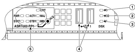
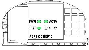
Table 1-1 shows the color or state of the LEDs in the Cisco ASR 1000 Series Route Processor-2 (RP-2) that indicate a successful installation. Figure 1-1 shows a view of the LEDs on the faceplate.

Note![]() Only Route Processor-2 (RP-2) and ESP-40 (Embedded Service Processor) are supported for installation on the Cisco ASR 1013 Router.
Only Route Processor-2 (RP-2) and ESP-40 (Embedded Service Processor) are supported for installation on the Cisco ASR 1013 Router.
Table 1-1 RP-2 Faceplate LEDs Indicating a Successful Installation (Cisco ASR 1013 Router)
Figure 1-1 RP-2 Faceplate LEDs for an Active RP (Cisco ASR 1013 Router)
Cisco ASR 1001 Router
The Cisco ASR 1001 Router faceplate has common components for each type of ASR 1001 Router configuration. Figure 1-2 shows the Cisco ASR1000 front panel LEDs of the Cisco ASR 1001 Router. Table 1-2 shows the color or state of the LEDs in the Cisco ASR 1001 Series Router.
Figure 1-2 Common LEDs for Cisco ASR 1001 Router
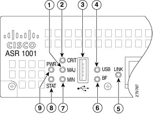
Table 1-2 Cisco ASR 1001 LED Color or State Details
|
|
|
|
|---|---|---|
Solid Green indicates Link, Flashing green indicates MGMT Ethernet port activity. |
||
Cisco ASR 1004 Router, Cisco ASR 1006 Router
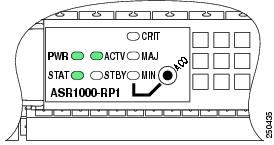
Table 1-3 shows the color or state of the LEDs in the Cisco ASR 1000 Series Route Processor (RP) that indicate a successful installation. Figure 1-3 shows a view of the LEDs on the faceplate.
|
|
|
|
|---|---|---|
Figure 1-3 RP Faceplate LEDs for an Active RP (Cisco ASR 1004 Router, Cisco ASR 1006 Router)
Cisco ASR 1002 Router
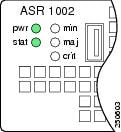
Table 1-4 shows the color or state of the LEDs in the Cisco ASR 1000 Series Route Processor (RP) that indicate a successful installation. Figure 1-4 shows a view of the LEDs on the faceplate.
|
|
|
|
|---|---|---|
Figure 1-4 RP Faceplate LEDs for an Active RP (Cisco ASR 1002 Router)
Cisco ASR 1000 Series Embedded Services Processors
Table 1-5 shows the color or state of the LEDs in the Cisco ASR 1000 Series Embedded Services Processor (ESP) that indicate a successful installation. Figure 1-5 shows a view of the LEDs on the faceplate.
|
|
|
|
|---|---|---|
Figure 1-5 ESP Faceplate LEDs for an Active ESP
Cisco ASR 1013 Router
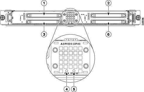
Table 1-6 shows the color or state of the LEDs in the Cisco ASR 1000 Series SPA Interface Processors (SIP) that indicate a successful installation. Figure 1-6 shows a view of the LEDs on the faceplate.
|
|
|
|
|---|---|---|
In the Cisco ASR 1013 Router, each Cisco ASR1000- SIP40 supports:
–![]() Four half-height (¼ Rate or full rate or combination) SPAs with up to 24 ports per SPA
Four half-height (¼ Rate or full rate or combination) SPAs with up to 24 ports per SPA
–![]() Two full-height (¼ Rate or full rate or combination) SPAs with up to 48 ports per SPA
Two full-height (¼ Rate or full rate or combination) SPAs with up to 48 ports per SPA
–![]() Two half-height and 1 full-height combination that does not exceed 96 ports
Two half-height and 1 full-height combination that does not exceed 96 ports
Note![]() If ASR-SIP10 is inserted in slot 0 to 5 of a Cisco ASR 1013 Router then you need to upgrade CPLD and ROMMON. If ASR-SIP40 is inserted in slot 4 or 5, it behaves like the ASR-SIP10.
If ASR-SIP10 is inserted in slot 0 to 5 of a Cisco ASR 1013 Router then you need to upgrade CPLD and ROMMON. If ASR-SIP40 is inserted in slot 4 or 5, it behaves like the ASR-SIP10.
Figure 1-6 SIP Faceplate LEDs (Cisco ASR 1013 Router)
Cisco ASR 1004 Router, Cisco ASR 1006 Router
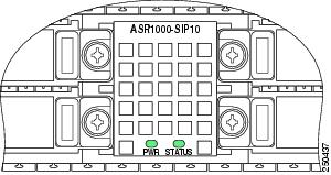
Table 1-7 shows the color or state of the LEDs in the Cisco ASR 1000 Series SPA Interface Processors (SIP) that indicate a successful installation. Figure 1-7 shows a view of the LEDs on the faceplate.
|
|
|
|
|---|---|---|
Figure 1-7 SIP Faceplate LEDs (Cisco ASR 1004 Router, Cisco ASR 1006 Router)
Cisco ASR 1002 Router
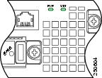
Table 1-8 shows the color or state of the LEDs in the Cisco ASR 1000 Series SPA Interface Processors (SIP) that indicate a successful installation. Figure 1-8 shows a view of the LEDs on the faceplate.
|
|
|
|
|---|---|---|
Figure 1-8 SIP Faceplate LEDs (Cisco ASR 1002 Router)
Shared Port Adapters
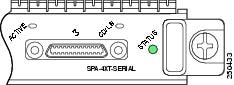
Table 1-9 shows the color or state of the LED the shared port adapter (SPA) that indicates a successful installation. Figure 1-9 shows a view of the LED on the faceplate.
|
|
|
|
|---|---|---|
Cisco ASR 1001 Built-in Gigabit Ethernet SPA LEDs
The Cisco ASR 1001 Router has a Built-in Gigabit Ethernet SPA, which is installed. Table 1-10 shows the Built-in SPA LEDs details.
Table 1-10 Cisco ASR 1001 Router Built-in Gigabit Ethernet SPA Successful Installation
AC and DC Power Supplies
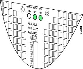
Table 1-11 shows the color or state of the LEDs that indicate a successful installation. Figure 1-10 shows a view of the LEDs on the faceplate.
|
|
|
|
|---|---|---|
Figure 1-10 AC and DC Power Supply Faceplate LEDs
Checking Status Using show Commands
Use the show platform and show environment all commands to check the online and environmental status of each FRU after installation.
The show platform command displays the online status information for router FRUs. The State column in show platform command output should display “ok” for SIPs, SPAs, power supplies, and fans. For RPs (shown as R0, R1) and ESPs (shown as F0, F1), the State column should display “ok, active” or “ok, standby.”
Note![]() There is only one LED for each Power Supply on Cisco ASR 1001 Router and it is green when powered-up.
There is only one LED for each Power Supply on Cisco ASR 1001 Router and it is green when powered-up.
Router# show platform
The show environment all command displays system temperature, voltage, fan, and power supply conditions. (It does not display environmental information for SPAs.) The State column in show environment all output should show “Normal,” except for fans where it indicates fan speed. A fan speed of 65% is normal.
Router# show environment all
The show environment all command output shows an example of one power supply in the Cisco ASR 1001 Router:
To display the Field Programmable Devices (FPD) on Cisco ASR 1001 Router, use the show hw-module all fpd command:
Router# show hw-module all fpd
To display the Field Programmable Devices (FPD) on Cisco ASR 1013 Router, use the show hw-module all fpd command:
When Installation Is Not Successful
This section discusses the following items to check or troubleshoot when installation is not successful:
- Physical Connections
- Mechanical Damage
- Alarm LED Is Illuminated
- Status LED Remains Amber
- LEDS Are Not Illuminated on a Power Supply
Physical Connections
Rule out an easily-fixed physical connection problem by verifying that:
Mechanical Damage
Examples of mechanical damage are a bent flange on a power supply or bent pins on a connector. If you detect mechanical damage:
Alarm LED Is Illuminated
If the CRIT, MAJ, or MIN alarm LED is illuminated, determine the cause of the alarm by doing one of the following:
- Review the alarm message. The logging alarm command must be enabled for the system to send alarm messages to the console. The following is an example of an alarm message that was generated when a SPA was removed without a graceful deactivation of the SPA:
*Aug 22 13:27:33.774: %ASR1000_OIR-6-REMSPA: SPA removed from subslot 1/1, interfaces disabled
*Aug 22 13:27:33.775: %SPA_OIR-6-OFFLINECARD: SPA (SPA-4XT-SERIAL) offline in subslot 1/1
- Enter the show facility-alarm status command. The following example shows a critical alarm that is generated when a SPA is removed fr om the system:
Note![]() A critical alarm "Active Card Removed OIR Alarm" is generated even if a SPA is removed after performing graceful deactivation.
A critical alarm "Active Card Removed OIR Alarm" is generated even if a SPA is removed after performing graceful deactivation.
Status LED Remains Amber
As Cisco IOS boots on a FRU, the status LED is amber or yellow. When Cisco IOS has successfully booted, the status LED becomes solid green.
If the status LED remains amber or yellow, check the console for alarm messages. The logging alarm command must be enabled for the system to send alarm messages to the console.
If there is no information on the console, some setting or error is not allowing Cisco IOS to boot. Contact Cisco Support; it is possible you might need to replace the FRU.
LEDS Are Not Illuminated on a Power Supply
If LEDs are not illuminated on the DC power supply, many times the problem is reversed polarity. Check the DC input power supply to see if the positive and negative lead wires are swapped.
If LEDs are not illuminated on the AC power supply, there is no input power or the power cord is not fully seated. If the power cord is fully seated, check the input power.
For More Information
For more information about the topics discussed in this chapter, see the following documents:
|
|
|
|---|---|
Cisco IOS Master Command List, All Releases Command Lookup Tool (Requires Cisco.com user ID and password)OL-17665-04 |
|
Graceful Deactivation of a SIP or SPA: Online insertion and removal (OIR) |
“Installing and Removing a SIP” chapter in the |
“Cisco ASR 1000 Series Routers Components Overview” chapter in the Cisco ASR 1000 Series Router Hardware Installation Guide |
|
Cisco ASR 1000 Series Aggregation Services Routers SIP and SPA Hardware Installation Guide |
|
Overview, Installation, and Detailed information of Cisco ASR 1001 Router |
|
 Feedback