Cisco ASR 1001 Router Description
The Cisco ASR 1001 Router is part of the Cisco aggregation services family of routers. The Cisco ASR 1001 Router offers a compact form factor router that satisfies customer demands such as low power consumption and decreased usage of rack space. The Cisco ASR 1001 Router has the route processor, embedded services processor, and SIP integrated within the chassis with one half-height SPA slot.
By default, the Cisco ASR 1001 Router is shipped with 4 GB of DRAM. To implement software redundancy, a minimum of 8 GB memory must be installed on the router.
The Cisco ASR 1001 Router supports:
-
ESP bandwidth 2.5 Gbps (default) to 5 Gbps of forwarding performance (optional software option)
-
ESP memory: 1-GB DRAM default; 1-GB DRAM maximum
-
Route-processor memory comes with 4-GB DRAM (default); 8-GB DRAM maximum
-
4-Gigabit Ethernet small form-factor pluggable (SFP) ports
For information about the SFP transceiver modules that are compatible with Cisco ASR 1002 Built-in Gigabit Ethernet Ports (4x1GE), refer to the “Modular Optics Compatibility” section in Cisco ASR 1000 Series Aggregation Services Routers SIP and SPA Hardware Installation Guide .
-
External USB flash memory 1-GB USB flash memory support
Cisco ASR 1001 Router Architecture
The Cisco ASR 1001 Router provides all the Cisco ASR 1000 Series Router features, services, and performance in a small form-factor chassis. The chassis contains a single integrated mainboard that implements all functions of the route processor (RP), a SPA embedded processor (SIP), a forwarding processor (ESP) and a built-in 4x1 GE SPA.
The SPA interface is connected to a built-in 4xGE SPA, a single half-height (HH) SPA bay, and one flexible integrated daughter card (IDC), providing additional SPA interfaces.
Cisco ASR 1001 Router hardware features include:
-
Front-to-back air flow, with 7 built-in cooling fans, numbered from left to right, zero (0) to 6.
-
Supports 1 + 1 redundant AC or DC power supplies.
-
A cover interlock prevents cover removal with power supplies installed.
-
Provides one half-height SPA bay (Bay 1 online insertion and removal (OIR) supported) and integrates a passive board, which consists of a standard SPA interface connector and an interface connector, to the mainboard.
-
Support for one factory-configurable integrated daughter card in SPA Bay 2. The integrated daughter card, in SPA Bay 2 is part of the base configuration, and is not an option.
-
Provides unique front panels for each integrated daughter card configuration.
-
8 GB internal flash
-
Console and Auxiliary RJ-45 ports
-
4 GB DRAM (default)
-
Forwarding Performance = 2.5G default, 5G with software license
The Cisco ASR 1001 Router can accommodate different integrated daughter cards. The chassis top cover includes the integrated daughter card front panel with a common base chassis.There will be different top covers for each integrated daughter cards and one for orders with no integrated daughter card.
The Cisco ASR 10001 Router can be shipped with different orderable configurations. The following IDC configurations are available:
 Note |
See the MIBs for the Cisco ASR 1001 Router appendix for information about the MIBs that can be used to manage these IDCs. |
-
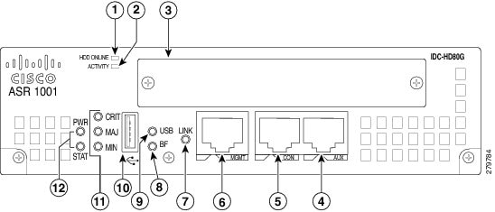
IDC-HD80G
IDC-HD80G can support a single 2.5-inch SATA HDD/SSD (see the following image).
|
1 |
HDD Online—LED indicates that the disk is ready and can be accessed |
7 |
LINK LED—Indicates MGMT Ethernet port activity |
|
2 |
HDD Activity—LED indicates that the disk is currently being accessed |
8 |
BF—Internal bootflash LED that indicates activity of the EUSB device |
|
3 |
HDD Slot—Slot into which the HDD is inserted (the figure shows an HDD inserted into the slot) |
9 |
USB LED |
|
4 |
AUX—RS-232 auxiliary port |
10 |
USB port—USB high-speed (480 Mbps) port used for secure key storage, VPN credentials storage, or bulk flash storage of image and configuration backup This USB port is an A port. |
|
5 |
CON—RS-232 console port |
11 |
STAT—Status LED |
|
6 |
MGMT—RJ-45 10/100/1000 management Ethernet port |
12 |
PWR—Power LED |
-
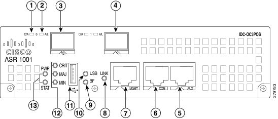
IDC-OC3POS
IDC-OC3POS can support two channels of OC3 (see the following image).
|
1 |
C/A—Carrier/Alarm LED |
8 |
LINK LED—Indicates MGMT Ethernet port activity |
|
2 |
A/L—Active/Loopback LED |
9 |
BF—Internal bootflash LED that indicates activity of the EUSB device |
|
3 |
POS OC3—Port 0 This POS port is a small form-factor pluggable (SFP) port. |
10 |
USB LED |
|
4 |
POS OC3—Port 1 This POS port is an SFP port. |
11 |
USB port—USB high-speed (480 Mbps) port used for secure key storage, VPN credentials storage, or bulk flash storage of image and configuration backup This USB port is an A port. |
|
5 |
AUX—RS-232 auxiliary port |
12 |
STAT—Status LED |
|
6 |
CON—RS-232 console port |
13 |
PWR—Power LED |
|
7 |
MGMT—RJ-45 10/100/1000 management Ethernet port |
— |
— |
-
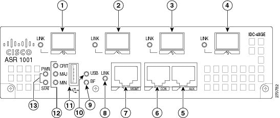
IDC-4XGE
IDC-4XGE can support up to four small form-factor pluggable (SFP) transceivers, each of which supports a 1-Gigabit Ethernet connection (see the following image).
|
1 |
GigabitEthernet—Port 0 This POS port is an SFP port. |
8 |
LINK LED—Indicates MGMT Ethernet port activity |
|
2 |
GigabitEthernet—Port 1 This POS port is an SFP port. |
9 |
BF—Internal bootflash LED that indicates activity of the EUSB device |
|
3 |
GigabitEthernet—Port 2 This POS port is an SFP port. |
10 |
USB LED |
|
4 |
GigabitEthernet—Port 3 This POS port is an SFP port. |
11 |
USB port—USB high-speed (480 Mbps) port used for secure key storage, VPN credentials storage, or bulk flash storage of image and configuration backup This USB port is an A port. |
|
5 |
AUX—RS-232 auxiliary port |
12 |
STAT—Status LED |
|
6 |
CON—RS-232 console port |
13 |
PWR—Power LED |
|
7 |
MGMT—RJ-45 10/100/1000 management Ethernet port |
— |
— |
- IDC-CHT1/E1
IDC-CHT1/E1 can support eight ports of fully channelized T1 or E1 interfaces (see Cisco ASR 1001 Router with IDC-CHT1/E1).

|
1 |
T1/E1 Ports—Ports 0 through 3 These T1/E1 ports are RJ-45 ports. |
7 |
BF—Internal bootflash LED that indicates activity of the EUSB device |
|
2 |
T1/E1 Ports—Ports 4 through 7 These T1/E1 ports are RJ-45 ports. |
8 |
USB LED |
|
3 |
AUX—RS-232 auxiliary port |
9 |
USB port—USB high-speed (480 Mbps) port used for secure key storage, VPN credentials storage, or bulk flash storage of image and configuration backup This USB port is an A port. |
|
4 |
CON—RS-232 console port |
10 |
STAT—Status LED |
|
5 |
MGMT—RJ-45 10/100/1000 management Ethernet port |
11 |
PWR—Power LED |
|
6 |
LINK LED—Indicates MGMT Ethernet port activity |
— |
— |
-
IDC-4XT3
IDC-4XT3 can support up to four unchannelized DS3 (44.736 Mbps) ports (see the following image).

|
1 |
C/A—Carrier/Alarm LED |
8 |
LINK LED—Indicates MGMT Ethernet port activity |
|
2 |
A/L—Active/Loopback LED |
9 |
BF—Internal bootflash LED that indicates activity of the EUSB device |
|
3 |
T3 TX Port—Transmit port 0 This T3 port uses a 1.0/2.3 RF connector with 75-ohm impedance. |
10 |
USB LED |
|
4 |
T3 RX Port—Receive port 0 This T3 port uses a 1.0/2.3 RF connector with 75-ohm impedance. |
11 |
USB port—USB high-speed (480 Mbps) port used for secure key storage, VPN credentials storage, or bulk flash storage of image and configuration backup This USB port is an A port. |
|
5 |
AUX—RS-232 auxiliary port |
12 |
STAT—Status LED |
|
6 |
CON—RS-232 console port |
13 |
PWR—Power LED |
|
7 |
MGMT—RJ-45 10/100/1000 management Ethernet port |
— |
— |
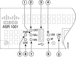
The following figures show the front panel of the Cisco ASR 1001 Router with the various IDCs. The following image shows the LEDs that are common to all configurations of the Cisco ASR 1001 Router.
|
1 |
MAJ LED—major alarm indicator |
6 |
BF—Internal bootflash LED indicates activity of the EUSB device |
|
2 |
CRIT LED—critical alarm indicator |
7 |
MIN LED —minor alarm indicator |
|
3 |
USB port— one USB high-speed (480Mbps) port used for secure key storage, storing of VPN credentials, or bulk flash storage for image and configuration backup |
8 |
STAT—status LED |
|
4 |
USB LED |
9 |
PWR—Power LED |
|
5 |
LINK LED indicates MGMT Ethernet port activity |
— |
— |
Note |
For detailed descriptions of the SPAs on which some of the IDCs are based, go to: http://www.cisco.com/en/US/products/ps6267/products_data_sheets_list.html |
Note |
There are two field-replaceable units in the Cisco ASR 1001 chassis. They are the DIMMs and eUSB. In order to service the components in the chassis, you must remove the power supplies and the chassis cover. For instructions, see the “Removing and Replacing the Cisco ASR 1001 Router DIMM Memory Modules” and the “Remove and Replace the eUSB Device on the Cisco ASR 1001 Router” sections in the Removing and Replacing FRUs from the Cisco ASR 1000 Series Routers chapter. |
Cisco ASR 1001 Router Faceplate Common Components
The Cisco ASR 1001 Router RP faceplate has common components for each type of ASR 1001 Router configuration. The preceding image and the following image show the Cisco ASR1000-RP faceplate with LEDs and connectors for all configurations of the Cisco ASR 1001 Router.

|
1 |
MGMT—One RJ-45 10/100/1000 management Ethernet port |
3 |
AUX—One RS-232 auxiliary port |
|
2 |
CON—One RS-232 console port |
— |
— |
Cisco ASR 1001 Chassis Front View
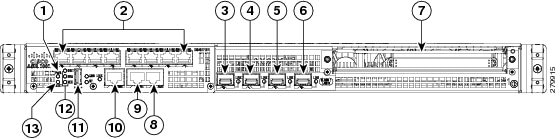
The following image shows the front of the Cisco ASR 1001 Router.
|
1 |
PWR—Power LED |
8 |
AUX—one RS-232 auxiliary port |
|
2 |
Integrated daughter card I/O space |
9 |
CON—one RS-232 console port |
|
3 |
GE 2/0 and 0/0—The built-in GE ports use industry standard front-panel removable SFP optics and SFP copper interfaces. |
10 |
MGMT —one RJ-45 10/100/1000 management Ethernet port |
|
4 |
GE 2/1 and 0/1 |
11 |
USB port |
|
5 |
GE 2/2 and 0/2 |
12 |
CRIT LED—critical alarm indicator MAJ LED—major alarm indicator MIN LED —minor alarm indicator |
|
6 |
GE 2/3 and 0/3 |
13 |
STAT—status LED |
|
7 |
One half-height SPA Bay 1 |
— |
Bottom slot of chassis is Bay 0 |
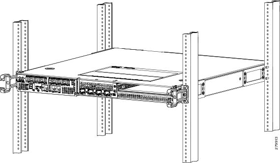
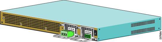
Cisco ASR 1001 Chassis Rear View
The following ima shows the rear of the Cisco ASR 1001 Router with seven fans and two AC or DC power supplies.
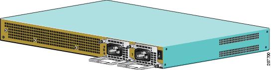
Seven internal fans draw cooling air into the chassis and across internal components to maintain an acceptable operating temperature. The fans are located at the rear of the chassis. A two-hole grounding lug is located on the side of the chassis. Each individual fan also has a fan fail status signal. The fan fail signal is asserted if the fan speed falls below 50% of the rated speed. The fans are numbered from zero (0) to 6, left to right.
Two power supplies, either two AC power supplies or two DC power supplies are accessed from the rear of the router.
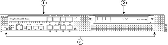
Cisco ASR 1001 Router Slot Numbering
The SPA bay numbering scheme for Cisco ASR 1001 Router is different from the Cisco ASR 1000 SIP card. The SPA ordering is: Built-in GE ports (SPA 0), SPA Bay 1 (SPA 1), and I/O Board (SPA 2).
The integrated daughter card is not necessarily a SPA; it could be any I/O, such as a harddrive or USB. When the daughter card is not a SPA, then SPA Bay 2 will be left blank and not present in the system.
The built-in GE ports are logically SPA bay 0 and will be addressed as GE 0/0/x. The half-height SPA slot is logically SPA bay 1 and ports will be addressed as 0/1/x. Ports on the integrated daughter card are logically in SPA bay 2 and will be addressed as 0/2/x.
The following image shows slot numbering for the Cisco ASR 1001 Router.
|
1 |
Slot 2 connected to the flexible integrated daughter card |
3 |
Slot 0 connected to the built-in 4x1GE SPA on the mainboard |
|
2 |
Slot 1 connected to the half-height SPA slot |
— |
— |
Cisco ASR 1001 Router Components
The Cisco ASR 1001 Router system is derived from the architecture of the other Cisco ASR 1000 Series routers. The Cisco ASR 1001 Router contains a single mainboard that provides all the functions of a Cisco ASR1000-RP (route proce4ssor), a Cisco ASR1000-SIP (carrier card), and a Cisco ASR1000-ESP (forwarding processor). This mainboard assembly also contains a built-in 4x1 GE SPA providing four SFP ports. The Cisco ASR1000-RP section of the mainboard provides all the traditional management interfaces (Ethernet, Console, Aux) and a storage interface (USB only). The Cisco ASR1000-SIP section provides one half-height SPA bay and a supports a flexible integrated daughter card. The Cisco ASR1000-ESP section provides a CPP based forwarding engine including a security coprocessor.
The main components of the Cisco ASR 1001 Router, ASR1000-RP1, ASR1000-ESP5, and ASR1000-SIP10 are fixed in the chassis and are not upgradeable, except for the power supplies and SPAs.
Cisco Embedded ASR1000-RP1 for Cisco ASR 1001 Router Description
The Cisco ASR 1000 Series route processor (embedded for the Cisco ASR 1001 Router) is the central control processor and runs the network operating system.
The Cisco embedded ASR1000-RP1 supports management interfaces such as the Ethernet network management port and console and auxiliary serial ports. It has LED status indicators and one USB port that can be used with smart cards for either secure key distribution or image or configuration file updates.
The Cisco embedded ASR1000-RP1 deviates from the other ASR Series Route Processor 1 for the Cisco ASR 1006 router and the Cisco ASR 1004 Router in the following ways:
- Bulk file storage is on a large eUSB device (to 8 GB supported) with no SATA hard-drive supported.
- Redundant Cisco route processor is not supported.
- Network clock changes. No second BITS clock input supported.
- A built-in 4xGE SPA is included. This shared port adapter provides four SFP-based GE connections.
The Cisco route processor common LEDs and indicators are shown in the “Common LEDs for Cisco ASR 1001 Route Processor” figure in the Cisco ASR 1001 Router Architecture section. The following table describes the Cisco ASR 1000 Series Route Processor LEDs.
|
LED Label |
LED |
Color—State |
Behavior Description |
|---|---|---|---|
|
PWR |
Power |
Solid green |
All power requirements are within specification |
|
Off |
Off. The router is in standby mode. |
||
|
STAT |
System status |
Solid green |
Cisco IOSD and other required processes have loaded successfully and are operating. |
|
Yellow |
ROMMON is running (including a permanent failure of RP software) or the Process Manager has declared a critical RP process (including IOSD) dead. A user can log in to recover. |
||
|
Red |
Occurs during system failure or power-up. |
||
|
CRIT |
Critical |
Solid Red |
Functions as a critical alarm indicator. The LED is lso a solid red during the boot process. |
|
MAJ |
Major |
Solid Red |
Major alarm indicator. |
|
MIN |
Minor |
Amber |
Minor alarm indicator. |
|
BOOT |
Internal eUSB bootflash LED |
Green |
Activity indicator. |
|
LINK |
10/100/1000 Interface LED |
Solid green |
Link with no activity. |
|
Flashing Green |
MGMT Ethernet port activity. |
||
|
Off |
No link. |
Cisco Embedded ASR1000-SIP10 and SPAs for the Cisco ASR 1001 Router Description
The Cisco embedded ASR1000-SIP10 is built into the Cisco ASR 1001 Router. The Cisco embedded ASR1000-SIP10 provides the physical and electrical termination for up to three SPAs, built-in 4xGE SPA, one half-height SPA bay, and one integrated daughter card (system configurable).
The Cisco embedded ASR1000-SIP10 interface, like the Cisco ASR 1006 Router and Cisco ASR 1004 Router, supports all Cisco embedded ASR1000-SIP10 functions and services. However, the Cisco embedded ASR1000-SIP10 differs in the following areas:
- Functions as the base board for Cisco embedded ASR1000-RP1
- Is not a field-replaceable unit (FRU) and does not support online insertion and removal (OIR).
Note |
Only the shared port adapter (SPA) on the Cisco embedded ASR1000-SIP10 in SPA Bay 1 of the Cisco ASR 1001 Router supports OIR. |
The Cisco ASR 1001 Router embedded ASR1000-RP1 also provides the circuitry for the built-in 4xGE SPA. Table 1 describes the built-in SPA LEDs.
|
Function |
Color |
Description |
|---|---|---|
|
GE SFP STATUS (one per port) |
Amber |
Indicates that the port is enabled by software, but there is a problem with the Ethernet link. |
|
Green |
Indicates that the port is enabled by software and there is a valid Ethernet link. |
Cisco ASR 1001 Router Integrated Daughter Card Description
The ASR 1001 Router supports different flexible integrated daughter cards with their own LEDs. Four of these integrated daughter cards are based on SPAs and use the same external I/O ports as those SPAs. One of the integrated daughter cards supports a single hard-disk-drive for other applications.
Table 1 describes the built-in SPA LEDs.
|
Function |
Color |
Description |
|---|---|---|
|
Daughter Card Port Status (one per port) |
Amber |
Amber indicates the port is enabled by software, but there is a problem with a port connection. |
|
Green |
Green indicates the port is enabled by software and operational. |
Cisco ASR1000-ESP for the Cisco ASR 1001 Router Description
The Cisco ASR 1001 Router supports the Cisco ASR1000-ESP2.5 and Cisco ASR1000-ESP5 (with license) embedded services processors.
Table 1 describes the Cisco ASR 1001 LEDs.
|
No. |
LED Label |
LED |
Color |
Behavior Description |
|---|---|---|---|---|
|
1 |
PWR |
Power |
Solid green |
All power supplies are within operational limits. |
|
Off |
Off. The router is in standby mode. |
|||
|
2 |
ACTV |
Active |
Green |
The embedded services processor is green when active. |
|
3 |
STAT |
STATUS |
Green |
Code has downloaded successfully and is operational. |
|
Yellow |
BOOT ROM has loaded successfully. |
|||
|
Red |
Not booted. |
|||
|
4 |
STBY |
Standby |
None |
Will always be off. |
You can upgrade the throughput of the ESP from 2.5 Gbps to 5 Gbps by applying a software-activated performance upgrade license and then reloading the router. If you want to determine the current throughput level of the ESP, run the show platform hardware throughput level command. The following example shows the output of this command before the performance upgrade license is applied:
Router# show platform hardware throughput level

The current throughput level is 2500000 kb/s
The following example shows the output of this command after the performance upgrade license is applied:
Router# show platform hardware throughput level
The current throughput level is 5000000 kb/s
For more information about the software-activated performance upgrade license, see the Cisco ASR 1000 Series Aggregation Services Routers Release Notes at the following location:
http://www.cisco.com/en/US/docs/routers/asr1000/release/notes/asr1k_rn_rel_notes.html
Power Supplies in the Cisco ASR 1001 Router
The Cisco ASR 1001 Router power supply module supports the following Cisco power supplies:
-
AC power supply operates between 85 to 264 VAC
-
–48 VDC power supply input range supported is -40.5 to -72 VDC.
The power supply generates +12 V and +5 V, which is distributed to the mainboard and fans. The +5 V is used to operate the power control devices. It also provides an operational +5 V, as needed.
The power supply units contain one or two fans that are only used for cooling the power supply. Each power supply is self contained and controls its own fan speed and fan redundancy.
The power supplies are hot pluggable from the rear of the chassis and can be removed or installed while the system is operating, without affecting any aspect of system performance. The Cisco ASR 1001 Router supports up to seven chassis-mounted cooling fans. Each fan provides an alarm output for error indication speed measurement. The fans are not field replaceable, but the system can meet the cooling requirements in the event of a single-fan failure.
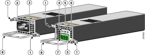
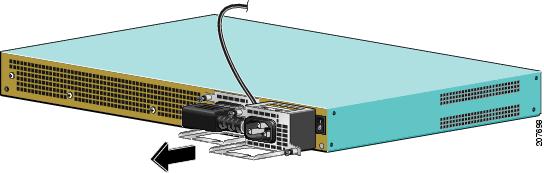
AC Power Supply for Cisco ASR 1001 Router
The AC power supply input inlet is an IEC connector. The current rating on the connector is 10 A. The AC power supply is secured into the chassis with two captive screws mounted on the faceplate.
The following image shows the AC power supply for the Cisco ASR 1001 Router.
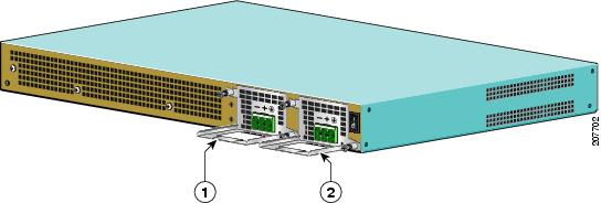
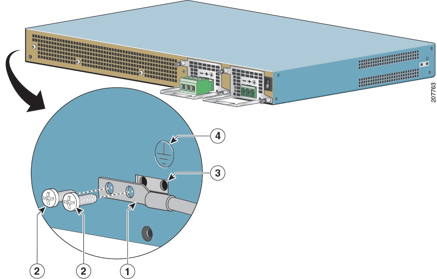
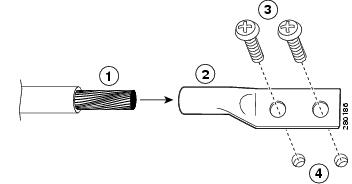
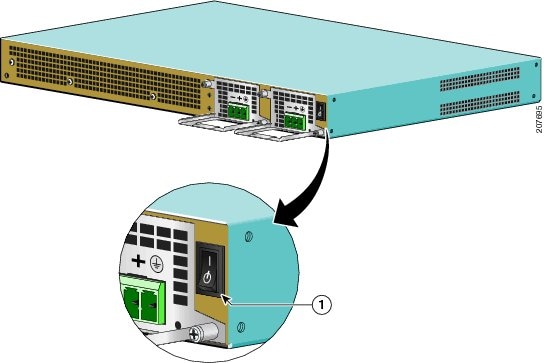
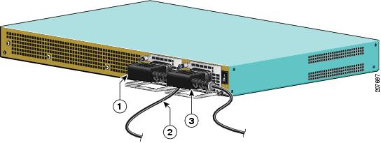
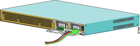
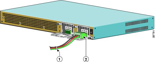
--48 VDC Power Supply for Cisco ASR 1001 Router
The –48 VDC power supply input connector accepts a Euro-style terminal block. It is compliant with safety agencies’ guidelines and electrical requirements of the supply. The DC power supply operates within specification from –40.5 to –72 VDC continuously once the power supply DC input reaches the threshold of –43.5 V.
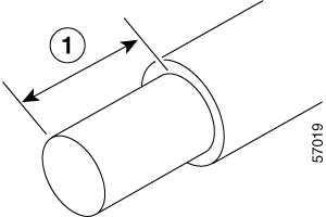
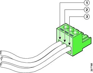
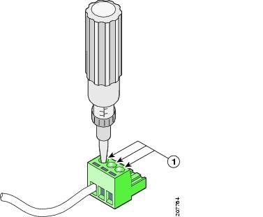
The –48 VDC power input connector Euro-style terminal block will accept three wires: one positive polarity, one negative polarity, and one ground wire. The connection order is negative (–), positive (+), and GND. The DC power supply is secured into the system chassis with two captive screws mounted on the faceplate.
The following image shows the –48 VDC power supplies for the Cisco ASR 1001 Router.
The output voltage alarm is declared when the output voltage is below the low end of the minimum or above the high end of the maximum limits. When the output voltage is above the high end of the minimum or below the low end of the maximum limits, the red state will not be activated.
The following table shows the –48 VDC power supply output voltage alarm ranges.
|
Output |
Minimum |
Maximum |
|---|---|---|
|
12V |
10.0-11.2V |
12.8-13.8V |
|
3.3V |
2.6 - 3.0 V |
None |
Power Cords Supported by the Cisco ASR 1001 Router
The following table lists the power cords that are supported by the Cisco ASR 1001 Router.
|
Power Cord Item Number |
Description |
|---|---|
|
15454-M-ACCBL-R2 |
AC Power Cable ANSI 220VAC Right Exit |
|
CAB-AC-RA |
Power Cord, 110 V, Right Angle |
|
CAB-ACA-RA |
Plug, Power Cord, Australian, 10 A, Right Angle |
|
CAB-ACC-RA |
Power Cord China, Right Angle |
|
CAB-ACE-RA |
Power Cord Europe, Right Angle |
|
CAB-ACI-RA |
Power Cord, Italian, Right Angle |
|
CAB-ACR-RA |
Power Cord Argentina, Right Angle |
|
CAB-ACS-RA |
Power Cord, Switzerland, Right Angle |
|
CAB-ACU-RA |
Power Cord UK, Right Angle |
|
CAB-IND-RA |
Power Cord India, Right Angle |
|
CAB-JPN-RA |
Power Cord-Japan, Right Angle |


 Feedback