Using Cisco Unified Communications Manager to Configure MGCP Gateway Support
Available Languages
Table Of Contents
Using Cisco Unified Communications Manager to Configure MGCP Gateway Support
Prerequisites for MGCP Gateway Support
Cisco Unified Communications Manager
Restrictions for Configuring MGCP Gateway Support
Information About MGCP Gateway Support
Configuring MGCP Gateway Support
Configuring MGCP on the Cisco VGD 1T3 Voice Gateway
Verifying MGCP Configuration on the Cisco VGD 1T3 Voice Gateway
Configuring Cisco Unified Communications Manager Switchover and MGCP Gateway Fallback
MGCP Gateway Registration with Cisco Unified Communications Manager
Benefits of Cisco Unified Communications Manager Switchover and MGCP Gateway Fallback
Verifying Cisco Unified Communications Manager Switchover and MGCP Gateway Fallback
Configuring POTS Dial Peers on MGCP Gateways
Restrictions for POTS Dial Peers on MGCP Gateways
Verifying Dial Peer Configuration for MGCP Gateways
Configuring Single-Point Configuration for MGCP Gateways
Prerequisites for Single-Point Configuration for MGCP Gateways
Verifying Single-Point Configuration for MGCP Gateways
Configuring Multicast Music-on-Hold Support for Cisco Unified Communications Manager
Prerequisites for Multicast Music-on-Hold (MOH)
Configuring MGCP PRI Backhaul and T1 CAS Support for Cisco Unified Communications Manager
Information About MGCP PRI Backhaul and T1 CAS Support
Verifying the MGCP PRI Backhaul Configuration
Configuration Examples for MGCP Gateway Support
MGCP Gateway with T1 CAS: Example
MGCP Gateway with T1 PRI: Example
Multicast Music-on-Hold: Example
Using Cisco Unified Communications Manager to Configure MGCP Gateway Support
This chapter provides information about using Cisco Unified Communications Manager to configure MGCP Gateway Support on the Cisco VGD 1T3 voice gateway platform. This chapter describes the MGCP Gateway support information and configuration procedures and includes the following:
•
Prerequisites for MGCP Gateway Support
•
•
•
•
Prerequisites for MGCP Gateway Support
Prerequisites for MGCP Gateway Support are defined in the following sections:
•
Cisco IOS Voice Gateway
The following prerequisites pertain specifically to the configuration of MGCP Gateway Support on a Cisco IOS voice gateway:
•
•
•
•
Cisco Unified Communications Manager
The following prequesities pertain specifically to RSVP Agent in a Cisco Unified Communications Manager network:
•
•
–
Restrictions for Configuring MGCP Gateway Support
•
•
•
•

Note
Information About MGCP Gateway Support
MGCP enables the remote control and management of voice and data communications devices at the edge of multiservice IP packet networks. Because of its centralized architecture, MGCP overcomes the distributed configuration and administration problems inherent in the use of protocols such as H.323. MGCP simplifies the configuration and administration of voice gateways and supports multiple (redundant) call agents, eliminating the potential for a single point of failure in controlling the Cisco IOS gateway in the network.
MGCP can be configured as a master or slave protocol to ensure that the gateway receives and executes the configuration, control, and management commands that are issued by Cisco Unified Communications Manager. The MGCP gateway is under the control of Cisco Unified Communications Manager.
MGCP uses endpoints and connections to construct a call. Endpoints are sources of or destinations for data and can be physical or logical locations identifying a device. The voice ports on the Cisco MGCP gateway are its endpoints. Connections can be point-to-point or multipoint. Cisco Unified Communications Manager acts as the MGCP call agent, managing connections between endpoints and controlling how the Cisco IOS gateway functions.
Figure 1 shows a typical MGCP gateway that is controlled by an MGCP call agent.
Figure 1 MGCP Gateway Controlled by Cisco Unified Communications Manager
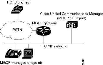
The MGCP gateway receives most of its required configuration from the call agent. To configure an MGCP gateway, you simply identify the Cisco Unified Communications Manager server associated with the gateway and identify the gateway to the call agent. The MGCP gateway handles the translation between voice signals and the packet network and interacts with the Cisco Unified Communications Manager server. The server performs signal and call processing.
Configuring MGCP Gateway Support
This section contains the following procedures:
•
•
•
•
•
•
•
•
•
•
•
•
Configuring MGCP on the Cisco VGD 1T3 Voice Gateway
Perform this task to configure MGCP on the Cisco VGD 1T3 voice gateway to support Cisco Unified Communications Manager.
SUMMARY STEPS
1.
2.
3.
4.
5.
6.
7.
8.
9.
10.
11.
12.
DETAILED STEPS
Verifying MGCP Configuration on the Cisco VGD 1T3 Voice Gateway
The show commands described in this section can be used to verify the MGCP configuration.
SUMMARY STEPS
1.
2.
3.
DETAILED STEPS
Step 1
Use the show running-config command to verify that MGCP is enabled on the voice gateway:
Router# show running-config...hostname vgd 1t3!...mgcpmgcp call-agent 10.0.0.21 service-type mgcp version 0.1mgcp dtmf-relay voip codec all mode out-of-band!ccm-manager mgcp!interface Ethernet0/1ip address 10.10.2.23 255.255.255.0half-duplexStep 2
Use the show interfaces gigabitEthernet command to verify that a Gigabit Ethernet interface is configured to communicate with the Cisco Unified Communications Manager server, for example:
Router# show interfaces gigabitEthernet0/0interface GigabitEthernet0/0ip address 10.1.200.68 255.255.0.0duplex autospeed autonegotiation autono keepaliveno cdp enableno mop enabled!Step 3
Use the show mgcp command to display the MGCP settings on the CiscoVGD 1T3 voice gateway:
Router# show mgcpMGCP Admin State ACTIVE, Oper State ACTIVE - Cause Code NONE!MGCP call agent with IP address for Cisco Unified Communications Manager:MGCP call-agent: 10.0.0.21 2427 Initial protocol service is MGCP, v. 0.1MGCP block-newcalls DISABLEDMGCP send RSIP for SGCP is DISABLEDMGCP quarantine mode discard/stepMGCP quarantine of persistent events is ENABLED!DTMF-relay voip codec parameters:MGCP dtmf-relay voip codec all mode out-of-bandMGCP dtmf-relay for VoAAL2 disabled for all codec typesMGCP voip modem passthrough mode: CISCO, codec: g711ulaw, redundancy: DISABLED,MGCP voaal2 modem passthrough mode: NSE, codec: g711ulawMGCP TSE payload: 0MGCP Network (IP/AAL2) Continuity Test timer: 200MGCP 'RTP stream loss' timer: 5MGCP request timeout 500, MGCP request retries 3MGCP rtp unreachable timeout 1000MGCP gateway port: 2427, MGCP maximum waiting delay 3000MGCP restart delay 0, MGCP vad DISABLEDMGCP simple-sdp DISABLEDMGCP undotted-notation DISABLEDMGCP codec type g711ulaw, MGCP packetization period 20MGCP JB threshold lwm 30, MGCP JB threshold hwm 150MGCP LAT threshold lmw 150, MGCP LAT threshold hwm 300MGCP PL threshold lwm 1000, MGCP PL threshold hwm 10000MGCP CL threshold lwm 1000, MGCP CL threshold hwm 10000MGCP playout mode is adaptive 60, 4, 200 in msecMGCP IP ToS low delay disabled, MGCP IP ToS high throughput disabledMGCP IP ToS high reliability disabled, MGCP IP ToS low cost disabledMGCP IP RTP precedence 5, MGCP signaling precedence: 3MGCP default package: line-packageMGCP supported packages: gm-package dtmf-package trunk-package line-packagehs-package rtp-package ms-package dt-package sst-packagc-packageMGCP VoAAL2 ignore-lco-codec DISABLEDMGCP T.38 Fax is DISABLED
Note
Configuring Cisco Unified Communications Manager Switchover and MGCP Gateway Fallback
This section describes how to configure Cisco Unified Communications Manager failover capabilities on the MGCP gateway.
Switchover (Failover)
Cisco IOS gateways can maintain links to up to two backup Cisco Unified Communications Manager servers in addition to a primary Cisco Unified Communications Manager. This redundancy enables a voice gateway to switchover to a backup if the gateway loses communication with the primary. The backup server takes control of the devices that are registered with the primary Cisco Unified Communications Manager. The second backup takes control of the registered devices if both the primary and first backup Cisco Unified Communications Manager fail. The gateway preserves existing connections during a switchover to a backup Cisco Unified Communications Manager.
When the primary Cisco Unified Communications Manager server becomes available again, control reverts to that server. Reverting to the primary server can occur immediately, after a configurable amount of time, or only when all connected sessions are released.
Switchback
Switchback is the process a voice gateway uses to reestablish communication with the primary Cisco Unified Communications Manager server when the server becomes available again. Switchback can occur immediately, at a specified time after the last active call ends, or after a specified length of time.
MGCP Gateway Fallback
The MGCP gateway maintains a remote connection to a centralized Cisco Unified Communications Manager cluster by sending MGCP keepalive messages to the Cisco Unified Communications Manager server at 15-second intervals. If the active Cisco Unified Communications Manager server fails to acknowledge receipt of the keepalive message within 30 seconds, the gateway attempts to switch over to the next available Cisco Unified Communications Manager server.
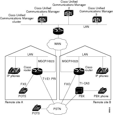
If none of the Cisco Unified Communications Manager servers respond, the gateway switches into fallback mode and reverts to the default H.323 session application for basic call control. H.323 is a standardized communication protocol that enables dissimilar devices to communicate with each other through use of a common set of codecs, call setup and negotiating procedures, and basic data transport methods. The gateway processes calls on its own using H.323 until one of the Cisco Unified Communications Manager connections is restored.
Figure 2 illustrates a typical VoIP network topology in which MGCP gateway fallback is supported.
Figure 2 Typical VoIP Network Topology Supporting the MGCP Gateway Fallback Feature
The MGCP Gateway Fallback feature provides the following functionality:
•
Any transient MGCP calls (that is, calls that are not in the connected state) are cleared at the onset of the fallback transition and must be attempted again later.
•
Except for ISDN T1 PRI calls, all the MGCP calls that are active at the time of fallback are preserved, but transient calls are released. When a user completes (hangs up) an active MGCP call, the MGCP application handles the on-hook event and clears all call resources.
•
When the fallback mode is in effect, the affected MGCP gateway repeatedly tries to open a TCP connection to a Cisco Unified Communications Manager server in the prioritized list of call agents. This process continues until one of the Cisco Unified Communications Manager servers in the prioritized list responds.
The TCP open request from the MGCP gateway is honored, and the gateway reverts to MGCP mode. The gateway sends a Restart-in-Progress (RSIP) message to begin registration with the responding Cisco Unified Communications Manager.
All currently active calls that are initiated and set up during the fallback period are maintained by the default H.323 session application, except ISDN T1 PRI calls. Transient calls are released. After rehome occurs, the new Cisco Unified Communications Manager assumes responsibility for controlling new IP telephony activity.
The following types of interfaces on the gateway are supported:
•
•
•
•
MGCP Gateway Registration with Cisco Unified Communications Manager
Table 1 describes what can happen when either the gateway loses connection to the primary Cisco Unified Communications Manager or the gateway also loses connection to all backup Cisco Unified Communications Manager servers.
Any calls at the time of reregistration (even those in a transient state such as call setup) remain undisturbed. The newly registered Cisco Unified Communications Manager determines the status of existing calls and maintains or deletes them as appropriate.
Benefits of Cisco Unified Communications Manager Switchover and MGCP Gateway Fallback
•
•
•
SUMMARY STEPS
1.
2.
3.
4.
5.
6.
7.
8.
9.
10.
DETAILED STEPS
Verifying Cisco Unified Communications Manager Switchover and MGCP Gateway Fallback
Use the show commands described in this section to verify the Cisco Unified Communications Manager switchover and MGCP gateway fallback configuration.
SUMMARY STEPS
1.
2.
3.
DETAILED STEPS
Step 1
Use the show running-config command to verify configuration of the Cisco Unified Communications Manager failover options, for example:
Router# show running-config...ccm-manager switchback immediateccm-manager fallback-mgcpccm-manager redundant-host 10.0.0.50ccm-manager mgcp...call application alternate DEFAULT!Step 2
Use the show ccm-manager command to verify the Cisco Unified Communications Manager failover options.
The following example shows one Cisco Unified Communications Manager backup server is configured. Switchback mode is set for immediate return to the primary Cisco Unified Communications Manager server as soon as the server is available.
Router# show ccm-managerMGCP Domain Name: router.cisco.comTotal number of host: 2Priority Status Host===================================================Primary Registered 10.0.0.201First backup Backup polling 10.0.0.50Second backup UndefinedCurrent active Communications Manager: 10.0.0.201Current backup Communications Manager: 10.0.0.50Redundant link port: 2428Failover Interval: 30 secondsKeepalive Interval: 15 secondsLast keepalive sent: 00:20:18 (elapsed time: 00:00:06)Last MGCP traffic time: 00:20:18 (elapsed time: 00:00:06)Last switchover time: NoneSwitchback mode: ImmediateStep 3
Use the show ccm-manager fallback-mgcp command to verify whether MGCP fallback is enabled and whether it is active or not (on or off), for example:
Router# show ccm-manager fallback-mgcpCurrent active Communications Manager: 10.00.71.29MGCP Fallback mode: Enabled/OFFLast MGCP Fallback start time: 00:00:00Last MGCP Fallback end time: 00:00:00
Note
Configuring POTS Dial Peers on MGCP Gateways
Perform this task to enable the POTS dial peers on your MGCP gateway to communicate with Cisco Unified Communications Manager.
When you have finished this procedure, the voice gateway is ready to communicate with Cisco Unified Communications Manager. It periodically sends out messages attempting to establish a connection. When the Cisco Unified Communications Manager configuration is complete, the connection should automatically establish itself. You should not have to make any further changes on the MGCP gateway.
Restrictions for POTS Dial Peers on MGCP Gateways
•
•
•
SUMMARY STEPS
1.
2.
3.
4.
5.
6.
7.
DETAILED STEPS
Verifying Dial Peer Configuration for MGCP Gateways
Use the show commands described in this section to verify the dial-peer configuration for MGCP gateways.
SUMMARY STEPS
1.
2.
DETAILED STEPS
Step 1
Use the show running-config command to verify the dial peer configuration.
The following example shows a configuration on MGCP voice gateways for T1 CAS with e&m-fgb emulation.
ccm-manager switchback immediateccm-manager fallback-mgcpccm-manager mgcp!controller T1 1/0:1framing esflinecode b8zsds0-group 1 timeslots 1-24 type e&m-fgb!voice-port 1/0:1:1!dial-peer voice 1 potsservice mgcpappdestination-pattern 91..........port 1/0:1:1The following example shows a configuration on MGCP gateways for VoIP calls, when the fallback feature is used.
dial-peer voice 555 voipapplication mgcpappdestination pattern 555...incoming-called-number 444...session-target ipv4:172.20.21.8codec g711ulaw
Note
Step 2
Use the show dial-peer voice command to verify the configuration of the POTS dial peer, for example:
Router# show dial-peer voice 1000VoiceEncapPeer1000information type = voice,description = `',tag = 1000, destination-pattern = `',answer-address = `', preference=0,numbering Type = `unknown'group = 1000, Admin state is up, Operation state is down,incoming called-number = `', connections/maximum = 0/unlimited,DTMF Relay = disabled,huntstop = disabled,in bound application associated: 'mgcpapp'out bound application associated: ''dnis-map =permission :bothincoming COR list:maximum capabilityoutgoing COR list:minimum requirementtype = pots, prefix = `',forward-digits defaultsession-target = `', voice-port = `',direct-inward-dial = disabled,digit_strip = enabled,register E.164 number with GK = TRUEConnect Time = 0, Charged Units = 0,Successful Calls=0, Failed Calls=0, Incomplete Calls=0Accepted Calls = 0, Refused Calls = 0,Last Disconnect Cause is "",Last Disconnect Text is "",Last Setup Time = 0.Step 3
Use the show voice port command to verify that the voice port is operational. The following is sample output for a T1 PRI backhaul voice port on a Cisco VGD 1T3 voice gateway:
Router# show voice port 4/0:1:23ISDN 4/0:1:23 - 4/0:1:23Type of VoicePort is XCCOperation State is DORMANTAdministrative State is UPNo Interface Down FailureDescription is not setNoise Regeneration is enabledNon Linear Processing is enabledNon Linear Mute is disabledNon Linear Threshold is -21 dBMusic On Hold Threshold is Set to -38 dBmIn Gain is Set to 0 dBOut Attenuation is Set to 0 dBEcho Cancellation is enabledEcho Cancellation NLP mute is disabledEcho Cancellation NLP threshold is -21 dBEcho Cancel Coverage is set to 128 msEcho Cancel worst case ERL is set to 6 dBPlayout-delay Mode is set to adaptivePlayout-delay Nominal is set to 60 msPlayout-delay Maximum is set to 1000 msPlayout-delay Minimum mode is set to default, value 40 msPlayout-delay Fax is set to 300 msConnection Mode is normalConnection Number is not setInitial Time Out is set to 15 sInterdigit Time Out is set to 10 sCall Disconnect Time Out is set to 60 sRinging Time Out is set to 180 sWait Release Time Out is set to 30 sSpe country is not configuredRegion Tone is set for USContinuity Test Tone CO1 is set to 2010Continuity Test Tone CO2 is set to 1780Station name None, Station number NoneTranslation profile (Incoming):Translation profile (Outgoing):DS0 channel specific status info:IN OUTPORT CH SIG-TYPE OPER STATUS STATUS TIP RING=============== == ============ ==== ====== ====== === ====4/0:1:23 01 xcc-voice up none none4/0:1:23 02 xcc-voice up none none
Note
Configuring Single-Point Configuration for MGCP Gateways
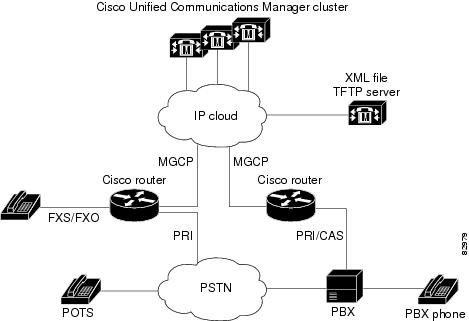
When you configure MGCP gateways to support Cisco Unified Communications Manager, you can use a centralized TFTP boot directory on a host device in your network to automatically download most of the configuration in the XML files. Each MGCP gateway in your VoIP network has an associated gateway-specific configuration that is stored in the centralized TFTP boot directory. A tailored XML file can be created and downloaded from the TFTP server to your designated MGCP gateway. The Cisco Unified Communications Manager server can be configured concurrently as a TFTP server.
When you make changes to the configuration in the database, a message is sent by Cisco Unified Communications Manager to the affected MGCP gateway, instructing the gateway devices to download the new XML configuration file. Each device has an XML parser that interprets the XML file according to its device-specific requirements. Cisco MGCP gateways, for example, translate the content of the XML file into specific Cisco IOS commands for local execution.
When an MGCP gateway is first started up, it is preconfigured with the following information or it obtains the information through Dynamic Host Configuration Protocol (DHCP):
•
–
–
•
•
With this configuration information available at startup, the MGCP gateway downloads the XML file from the TFTP server. The gateway parses the XML file, converts the information to appropriate Cisco IOS configuration commands, and configures itself to run in the VoIP network. Finally, the gateway registers itself with Cisco Unified Communications Manager using an RSIP message. At that point, the MGCP gateway is ready for service in the network.
After a successful configuration download, the MGCP gateway saves the running configuration to nonvolatile random-access memory (NVRAM), which updates the startup configuration. Any manually-added configuration parameters are also saved to NVRAM if they were not previously saved. Manually-added configuration parameters are updates to the configuration that were made using the command-line interface (CLI). Manual configuration updates are separate from the automatic configuration updates made during the configuration download process.
In the event of a configuration failure, the MGCP gateway attempts to restore its current configuration by copying the startup configuration from NVRAM into the running configuration. Because this overwrites the running configuration, any manually added configuration parameters could be lost if they were not saved to NVRAM before running the automatic configuration-download process.
Figure 3 Single-Point Configuration for Cisco MGCP Gateways
Prerequisites for Single-Point Configuration for MGCP Gateways
•
•
SUMMARY STEPS
1.
2.
3.
4.
5.
Verifying Single-Point Configuration for MGCP Gateways
Use the show commands described in this section to verify the single-point configuration for MGCP gateways.
SUMMARY STEPS
1.
2.
DETAILED STEPS
Step 1
Use the show running-config command to verify the single-point download configuration, for example:
Router# show running-config...ccm-manager switchback immediateccm-manager fallback-mgcpccm-manager redundant-host 10.10.10.1ccm-manager mgcpccm-manager music-on-holdccm-manager config server 10.1.10.10ccm-manager config!Step 2
Use the show ccm-manager config-download command to verify the download status. The output indicates that four downloads were successful.
Router# show ccm-manager config-downloadConfiguration Auto-download Information=======================================Current version-id: {1645327B-F59A-4417-8E01-7312C61216AE}Last config-downloaded:00:00:49Current state: Waiting for commandsConfiguration Download statistics:Download Attempted : 4Download Successful : 4Download Failed : 0Configuration Attempted : 1Configuration Successful : 1Configuration Failed(Parsing): 0Configuration Failed(config) : 0Last config download command: New Registration
Note
Configuring Multicast Music-on-Hold Support for Cisco Unified Communications Manager
This section describes how to configure your gateway to provide music to customers on hold.
Prerequisites for Multicast Music-on-Hold (MOH)
The default router in the network for handling multicast traffic must have the following enabled:
•
•
•
•
Multicast Music-on-Hold
The Music-on-Hold (MOH) feature enables you to subscribe to a music streaming service when you are using a Cisco IOS MGCP voice gateway. Music streams from an MOH server to the voice interfaces of on-net and off-net callers that have been placed on hold. Cisco Communications Manager supports the capability to place callers on hold with music supplied from a streaming multicast MOH server. This integrated multicast capability is implemented through the H.323 signaling in Cisco Communications Manager.
By means of a preconfigured multicast address on the gateway, the gateway can "listen" for Real-Time Transport Protocol (RTP) packets that are broadcast from a default router in the network and can relay the packets to designated voice interfaces in the network. Whenever a called party places a calling party on hold, Cisco Communications Manager requests the MOH server to stream RTP packets to the "on-hold" interface through the preconfigured multicast address. In this way, RTP packets are relayed to appropriately configured voice interfaces that have been placed on hold. When you configure a multicast address on a gateway, the gateway sends an Internet Gateway Management Protocol (IGMP) "join" message to the default router, indicating to the default router that the gateway is ready to receive RTP multicast packets.
Multiple MOH servers can be present in the same network, but each server must have a different Class D IP address, and the address must be configured in Cisco Communications Manager and the MGCP voice gateways.
SUMMARY STEPS
1.
2.
3.
4.
5.
DETAILED STEPS
Verifying Music-on-Hold
Use the show commands described in this section to verify music-on-hold.
SUMMARY STEPS
1.
2.
DETAILED STEPS
Step 1
Use the show running-config command to verify the MOH configuration, for example:
Router# show running-config...ccm-manager redundant-host 10.0.0.21ccm-manager mgcpccm-manager music-on-holdccm-manager config server 10.0.0.21ccm-manager config!Step 2
Use the show ccm-manager music-on-hold command to display information about the currently active MOH sessions, for example:
Router#show ccm-manager music-on-holdMulticast RTP Packets Call IncomingAddress Port In/Out ID Protocol Interface10.10.20.22 16256 3000/3000 1 IGMP fe0/0
Note
Configuring MGCP PRI Backhaul and T1 CAS Support for Cisco Unified Communications Manager
This section describes the procedures for enabling MGCP PRI backhaul support on the Cisco VGD 1T3 voice gateway.
Prerequisites
The following prerequisites must be met to configure MGCP PRI backhaul support:
•
•
Restrictions
The following restrictions apply to configuration of MGCP PRI backhaul support:
•
•
•
•
Information About MGCP PRI Backhaul and T1 CAS Support
To configure MGCP PRI backhaul, you should understand the following concepts:
MGCP PRI Backhaul Overview
MGCP PRI backhaul is a method for transporting complete IP telephony signaling information from an ISDN PRI interface in an MGCP gateway to Cisco Unified Communications Manager using a highly reliable TCP connection. The gateway uses a single TCP connection to backhaul all ISDN D channels to Cisco Unified Communications Manager. The "SAP/Channel ID" parameter in the header of each message identifies individual D channels. In addition to carrying the backhaul traffic, the TCP keepalive mechanism also determines MGCP voice gateway connectivity to an available call agent.
MGCP PRI backhaul terminates all ISDN PRI Layer 2 (Q.921) signaling functions on the MGCP gateway while, at the same time, packaging all the ISDN PRI Layer 3 (Q.931) signaling information into packets for transmission to Cisco Unified Communications Manager through an IP tunnel over a TCP connection. This ensures the integrity of the Q.931 signaling information that passes through the network for managing IP telephony devices. A rich set of user-side and network-side ISDN PRI calling functions is supported by MGCP PRI backhaul.
The MGCP gateway also establishes a TCP link to the backup (secondary) Cisco Unified Communications Manager server. In the event of a Cisco Unified Communications Manager switchover, the secondary Cisco Unified Communications Manager server performs the MGCP PRI backhaul functions. During the switchover, all active ISDN PRI calls are preserved, and the affected MGCP gateway is registered with the new Cisco Unified Communications Manager server through a Restart-in-Progress (RSIP) message. In this way, continued gateway operation is ensured.
T1 CAS is supported in nonbackhaul fashion. Cisco Unified Communications Manager supports the following CAS signaling types: E&M, wink-start, and E&M delay-dial. E1 CAS is not supported.
ISDN NSF in Route Patterns
The MGCP Gateway Support for Cisco Unified Communications Manager Network Specific Facilities (NSF) feature supports the use of the ISDN NSF information element in the route pattern. This feature is compatible with Cisco Communications Manager 3.3(2) (formerly known as Cisco CallManager 3.3(2)) and later.
The route pattern design in Cisco Unified Communications Manager enables facilities or services to be invoked on a call-by-call basis. The NSF information element, which is used in ISDN PRI setup messages for outgoing calls, includes the carrier identification code (CIC) and service parameters. The NSF configuration is done in Cisco Unified Communications Manager as part of the route pattern for MGCP-controlled PRI ports. The NSF information element is inserted in the Q.931 stream so that the attached PSTN switch can interpret the information elements and select the service and route the call to a network.
With NSF configured, NSF can be used on a call-by-call basis. Without NSF configuration, you must configure associated gateways as standalone H.323 gateways for which NSF services are configured locally within the router. No configuration is required on the MGCP gateway to use the NSF feature.
Complete the following task to configure MGCP PRI backhaul on the Cisco VGD 1T3 voice gateway.
SUMMARY STEPS
1.
2.
3.
4.
5.
6.
7.
8.
9.
10.
11.
DETAILED STEPS
Verifying the MGCP PRI Backhaul Configuration
SUMMARY STEPS
To verify the MGCP PRI backhaul configuration, complete the following steps.
1.
2.
3.
DETAILED STEPS
Step 1
Use the show isdn status command to verify connectivity.
In the following sample output, the Layer 2 protocol is Q.921, and the Layer 3 protocol is CCM-MANAGER. This output verifies that the Layer 2 and Layer 3 protocols are configured to backhaul ISDN. If you are connected to a live line, you should see Layer 1 status as active and Layer 2 as MULTIPLE_FRAME_ESTABLISHED.
Router# show isdn status*00:03:34.423 UTC Sat Jan 1 2000Global ISDN Switchtype = primary-net5ISDN Serial1:23 interface!******* Network side configuration *******!dsl 0, interface ISDN Switchtype = primary-net5!**** Master side configuration ****!L2 Protocol = Q.921 L3 Protocol(s) = CCM-MANAGERLayer 1 Status:ACTIVELayer 2 Status:TEI = 0, Ces = 1, SAPI = 0, State = MULTIPLE_FRAME_ESTABLISHEDLayer 3 Status:NLCB:callid=0x0, callref=0x0, state=31, ces=0 event=0x0NLCB:callid=0x0, callref=0x0, state=0, ces=1 event=0x00 Active Layer 3 Call(s)Activated dsl 0 CCBs = 0Number of active calls = 0Number of available B-channels = 23Total Allocated ISDN CCBs = 0Step 2
Use the show ccm-manager command to view the registration status with Cisco Unified Communications Manager, for example:
Router# show ccm-managerMGCP Domain Name: AV-2620-4Priority Status Host============================================================Primary Registered 10.16.240.124First Backup Backup Ready 10.16.240.128Second Backup NoneCurrent active Call Manager: 10.16.240.124Backhaul/Redundant link port: 2428Failover Interval: 30 secondsKeepalive Interval: 15 secondsLast keepalive sent: 00:45:31 (elapsed time: 00:00:04)Last MGCP traffic time: 00:45:31 (elapsed time: 00:00:04)Last failover time: NoneSwitchback mode: GracefulMGCP Fallback mode: Not SelectedLast MGCP Fallback start time: 00:00:00Last MGCP Fallback end time: 00:00:00PRI Backhaul Link info:Link Protocol: TCPRemote Port Number: 2428Remote IP Address: 10.16.240.124Current Link State: OPENStatistics:Packets recvd: 32Recv failures: 0Packets xmitted: 32Xmit failures: 0PRI Ports being backhauled:Slot 1, port 0Configuration Auto-Download Information=======================================Current version-id: {1645327B-F59A-4417-8E01-7312C61216AE}Last config-downloaded:00:00:49Current state: Waiting for commandsConfiguration Download statistics:Download Attempted : 6Download Successful : 6Download Failed : 0Configuration Attempted : 1Configuration Successful : 1Configuration Failed(Parsing): 0Configuration Failed(config) : 0Last config download command: New RegistrationConfiguration Error History:FAX mode: ciscoStep 3
Use the show ccm-manager backhaul command to verify the PRI backhaul link information, for example:
Router# show ccm-manager backhaulPRI Backhaul Link info:Link Protocol: TCPRemote Port Number: 2428Remote IP Address: 10.20.71.38Current Link State: OPENStatistics:Packets recvd: 0Recv failures: 0Packets xmitted: 21Xmit failures: 0PRI Ports being backhauled:Slot 1, port 1For a description of the fields displayed in these output examples, see the individual commands in the Cisco IOS Voice Command Reference.
Configuration Examples for MGCP Gateway Support
This section provides the following configuration examples:
•
•
•
Note
MGCP Gateway with T1 CAS: Example
The following example shows MGCP fallback configured on a voice gateway with T1 CAS.
Current configuration : 2181 bytes!version 12.4no service single-slot-reload-enableservice timestamps debug uptimeservice timestamps log uptimeno service password-encryption!hostname Test-vgd1t3!logging rate-limit console 10 except errors!memory-size iomem 25voice-card 3!ip subnet-zero!no ip domain-lookupip domain-name example.com!no ip dhcp-client network-discoveryframe-relay switchingmgcpmgcp call-agent 10.0.0.21 service-type mgcp version 0.1mgcp dtmf-relay voip codec all mode out-of-bandmgcp rtp unreachable timeout 1000mgcp package-capability rtp-packageno mgcp timer receive-rtcpcall rsvp-sync!ccm-manager switchback immediateccm-manager fallback-mgcpccm-manager redundant-host 10.0.0.21ccm-manager mgcp!controller T1 3/0:1framing esflinecode b8zsds0-group 1 timeslots 1 type e&m-fgb!controller T1 4/0:1framing sflinecode ami!interface FastEthernet0/0:1:23ip address 10.0.0.21 255.255.255.224duplex autospeed auto!interface Serial0/0:1:23ip address 10.0.0.21 255.255.255.224encapsulation frame-relayno keepaliveframe-relay interface-dlci 300!interface Serial1/0:1:23no ip addressshutdownclockrate 2000000!interface Ethernet2/0:1:23ip address 10.0.0.21 255.255.255.224half-duplex!interface TokenRing2/0no ip addressshutdownring-speed 16!ip classlessip route 10.0.0.21 255.255.255.0 14.0.0.1ip route 10.0.0.21 255.255.255.0 14.0.0.1ip route 10.0.0.21 255.255.255.0 14.0.0.1ip route 10.0.0.21 255.255.255.0 14.0.0.1ip route 10.0.0.21 255.255.255.255 Ethernet2/0ip route 10.0.0.21 255.255.255.255 Ethernet2/0no ip http server!snmp-server manager!voice-port 1/0:1!voice-port 1/0:2!voice-port 1/1:1!voice-port 1/1:2!voice-port 3/0:1!dial-peer cor custom!dial-peer voice 44 potsapplication mgcpappdestination-pattern 4301port 1/1:0!dial-peer voice 55 potsapplication mgcpappdestination-pattern 4302port 1/1:1!dial-peer voice 85 voipdestination-pattern 805....session target ipv4:10.0.0.21codec g711ulaw!dial-peer voice 33 potsservice mgcpappdestination-pattern 807....port 3/0:1!line con 0exec-timeout 0 0line aux 0line vty 0 4loginend
Note
MGCP Gateway with T1 PRI: Example
The following example shows MGCP fallback configured on a voice gateway with T1 PRI ports.
version 12.4no parser cacheno service single-slot-reload-enableservice timestamps debug datetime msecservice timestamps log datetime msecno service password-encryption!hostname vgd1t3!logging rate-limit console 10 except errors!voice-card 1!ip subnet-zero!no ip domain-lookup!no ip dhcp-client network-discoverymgcpmgcp call-agent 172.16.240.124 2427 service-type mgcp version 0.1mgcp dtmf-relay voip codec all mode out-of-bandmgcp rtp unreachable timeout 1000 action notifymgcp modem passthrough voip mode ciscomgcp package-capability rtp-packagemgcp package-capability sst-packageno mgcp timer receive-rtcp!ccm-manager fallback-mgcpccm-manager redundant-host CM-Bccm-manager mgcpccm-manager music-on-holdccm-manager config server cm-accm-manager config!controller T1 1/0:1framing esflinecode b8zspri-group timeslots 1-24 service mgcp!controller T1 1/0:2framing esflinecode b8zspri-group timeslots 1-24 service mgcp!interface Serial1/0:23no ip addressno logging event link-statusisdn switch-type primary-niisdn incoming-voice voiceisdn T306 30000isdn bind-l3 ccm-managerno cdp enable!voice-port 1/0:23!dial-peer voice 9991023 potsapplication mgcpappdirect-inward-dialport 1/0:23!dial-peer voice 9991123 potsapplication mgcpappdirect-inward-dialport 1/1:23!dial-peer voice 1640001 potsdestination-pattern 16.....direct-inward-dialport 1/0:23!line con 0exec-timeout 0 0line aux 0line vty 0 4login!end
Note
Multicast Music-on-Hold: Example
The following example shows multicast MOH configured for an MGCP voice gateway:
version 12.4no parser cacheno service single-slot-reload-enableservice timestamps debug datetime msecservice timestamps log datetime msecno service password-encryption!hostname voice-3640!logging rate-limit console 10 except errors!memory-size iomem 10voice-card 1!ip subnet-zero!ip domain-name example.com!no ip dhcp-client network-discoverymgcpmgcp call-agent 10.0.0.21 2427 service-type mgcp version 0.1mgcp dtmf-relay voip codec all mode out-of-bandmgcp rtp unreachable timeout 1000mgcp modem passthrough voip mode ciscomgcp package-capability rtp-packagemgcp package-capability sst-packageno mgcp timer receive-rtcpcall rsvp-sync!ccm-manager redundant-host 10.0.0.21ccm-manager mgcpccm-manager music-on-holdccm-manager config server 10.0.0.21ccm-manager config!controller T1 2/0:1framing sflinecode amids0-group 0 timeslots 1 type e&m-fgb!controller T1 2/0:2framing sflinecode ami!interface FastEthernet0/0:1ip address 10.0.0.21 255.255.255.0no ip mroute-cacheduplex autospeed autono cdp enable!voice-port 1/0:0!voice-port 1/0:1!voice-port 2/0:0!dial-peer cor custom!dial-peer voice 125 potsapplication mgcpappport 1/0:0!dial-peer voice 150 potsservice mgcpappport 2/0:0!line con 0exec-timeout 0 0line aux 0line vty 0 4login!no scheduler max-task-timescheduler allocate 4000 4000!endAdditional References
•
•
•
•
•
•
CCDE, CCENT, CCSI, Cisco Eos, Cisco HealthPresence, Cisco IronPort, the Cisco logo, Cisco Lumin, Cisco Nexus, Cisco Nurse Connect, Cisco Pulse, Cisco StackPower, Cisco StadiumVision, Cisco TelePresence, Cisco Unified Computing System, Cisco WebEx, DCE, Flip Channels, Flip for Good, Flip Mino, Flipshare (Design), Flip Ultra, Flip Video, Flip Video (Design), Instant Broadband, and Welcome to the Human Network are trademarks; Changing the Way We Work, Live, Play, and Learn, Cisco Capital, Cisco Capital (Design), Cisco:Financed (Stylized), Cisco Store, and Flip Gift Card are service marks; and Access Registrar, Aironet, AllTouch, AsyncOS, Bringing the Meeting To You, Catalyst, CCDA, CCDP, CCIE, CCIP, CCNA, CCNP, CCSP, CCVP, Cisco, the Cisco Certified Internetwork Expert logo, Cisco IOS, Cisco Press, Cisco Systems, Cisco Systems Capital, the Cisco Systems logo, Cisco Unity, Collaboration Without Limitation, Continuum, EtherFast, EtherSwitch, Event Center, Explorer, Fast Step, Follow Me Browsing, FormShare, GainMaker, GigaDrive, HomeLink, iLYNX, Internet Quotient, IOS, iPhone, iQuick Study, IronPort, the IronPort logo, Laser Link, LightStream, Linksys, MediaTone, MeetingPlace, MeetingPlace Chime Sound, MGX, Networkers, Networking Academy, Network Registrar, PCNow, PIX, PowerKEY, PowerPanels, PowerTV, PowerTV (Design), PowerVu, Prisma, ProConnect, ROSA, ScriptShare, SenderBase, SMARTnet, Spectrum Expert, StackWise, The Fastest Way to Increase Your Internet Quotient, TransPath, WebEx, and the WebEx logo are registered trademarks of Cisco Systems, Inc. and/or its affiliates in the United States and certain other countries.
All other trademarks mentioned in this document or website are the property of their respective owners. The use of the word partner does not imply a partnership relationship between Cisco and any other company. (0908R)
Any Internet Protocol (IP) addresses and phone numbers used in this document are not intended to be actual addresses and phone numbers. Any examples, command display output, network topology diagrams, and other figures included in the document are shown for illustrative purposes only. Any use of actual IP addresses or phone numbers in illustrative content is unintentional and coincidental.
© 2008-2009 Cisco Systems, Inc. All rights reserved.
 Feedback
Contact Cisco
- Open a Support Case

- (Requires a Cisco Service Contract)
This Document Applies to These Products
- Collaboration Endpoints - Retired Products
- Conferencing - Retired Products
- Contact Center - Retired Products
- Optical Networking - Retired Products
- Routers - Retired Products
- Security - Retired Products
- Servers - Unified Computing (UCS) Retired Products
- Storage Networking Retired Products
- Switches - Retired Products
- Video - Retired Products
- Wireless - Retired Products