Connecting Cisco Enhanced EtherSwitch Service Modules to the Network
Available Languages
Table Of Contents
Connecting Cisco Enhanced EtherSwitch Service Modules to the Network
Cisco Enhanced EtherSwitch Services Modules
Cisco Enhanced EtherSwitch Service Module Overview
16-Port Cisco Enhanced EtherSwitch Service Modules
24-Port Cisco Enhanced EtherSwitch Service Modules
48-Port Cisco Enhanced EtherSwitch Service Modules
Cisco Enhanced EtherSwitch Service Module Ports
Cisco Enhanced EtherSwitch Service Module LEDs
Power Considerations for the Router
Power Considerations for the Service Module
Connecting to the Enhanced EtherSwitch Service Module Ports
Obtaining Documentation, Obtaining Support, and Security Guidelines
Connecting Cisco Enhanced EtherSwitch Service Modules to the Network
Revised: March 15, 2009, OL-18327-02
This guide describes how to connect Cisco enhanced EtherSwitch service modules to your network. It contains the following sections:
•
Cisco Enhanced EtherSwitch Services Modules
•
•

Note
http://www.cisco.com/en/US/docs/routers/access/interfaces/nm/hardware/installation/guide/connswh.html
Note
http://www.cisco.com/en/US/docs/routers/access/interfaces/nm/hardware/installation/guide/conneths.html
Cisco Enhanced EtherSwitch Services Modules
Cisco enhanced EtherSwitch service modules are complete switching platforms with increased switch to switch traffic load capacity, with Power over Ethernet (PoE) capability, and capable of supporting the following features:
•
•
•
•
For information about these and other features available in Cisco enhanced EtherSwitch service modules, see the Cisco Enhanced EtherSwitch Service Modules Configuration Guide at the following URL:
http://www.cisco.com/en/US/docs/routers/access/interfaces/software/feature/guide/eesm_sw.html
Note
This section describes the Cisco enhanced EtherSwitch service modules. It contains the following sections:
•
•
•
Accessibility
These Cisco enhanced EtherSwitch service modules can be configured using the Cisco command-line interface (CLI). The CLI conforms to code 508 because it is text based and it relies on a keyboard for navigation. All functions of the router can be configured and monitored through the CLI.
For a complete list of guidelines and Cisco products' adherence to accessibility, see Cisco Accessibility Products at the following URL:
http://www.cisco.com/web/about/responsibility/accessibility/products
Cisco Enhanced EtherSwitch Service Module Overview
The Cisco enhanced EtherSwitch service modules are switch modules to which you can connect Cisco IP phones, Cisco wireless access point workstations, and other network devices such as servers, routers, switches, and other network switch modules.

Caution
The following modules are available with this release of the hardware:
•
•
•
•
•
•
•
•
•
•
Note
Note
Table 1 shows the Cisco router platforms that support the Cisco enhanced EtherSwitch service modules.
16-Port Cisco Enhanced EtherSwitch Service Modules
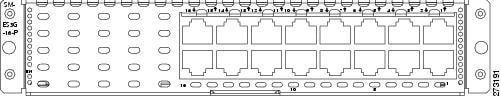
Figure 1, Figure 2, and Figure 3 show the 16-port Cisco enhanced EtherSwitch service modules.
Figure 1 SM-ES2-16-P Enhanced EtherSwitch Service Module
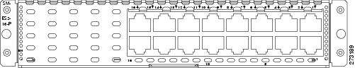
Figure 2 SM-ES3-16-P Enhanced EtherSwitch Service Module
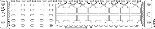
Figure 3 SM-ES3G-16-P Enhanced EtherSwitch Service Module
24-Port Cisco Enhanced EtherSwitch Service Modules
Figure 4, Figure 5, Figure 6, and Figure 7 show the 24-port Cisco enhanced EtherSwitch service modules.
Figure 4 SM-ES2-24 Enhanced EtherSwitch Service Module
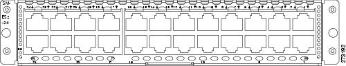
Figure 5 SM-ES2-24-P Enhanced EtherSwitch Service Module

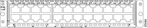
Figure 6 SM-ES3-24-P Enhanced EtherSwitch Service Module
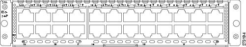
Figure 7 SM-ES3G-24-P Enhanced EtherSwitch Service Module
48-Port Cisco Enhanced EtherSwitch Service Modules
Figure 8, Figure 9, and Figure 10 show the 48-port Cisco enhanced EtherSwitch service modules.
Figure 8 SM-D-ES2-48 Cisco Enhanced EtherSwitch Service Module
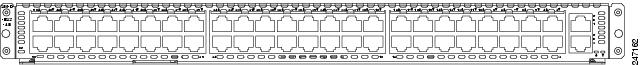
Figure 9 SM-D-ES3-48-P Cisco Enhanced EtherSwitch Service Module

Figure 10 SM-D-ES3G-48-P Cisco Enhanced EtherSwitch Service Module

Cisco Enhanced EtherSwitch Service Module Ports
The following sections describes the port types and port numbering on the service modules:
•
Port Numbering
The Ethernet ports are numbered right to left, top to bottom. The port numbering scheme to configure the ports on the Cisco enhanced EtherSwitch service module includes the port type (such as fa or fastethernet for Fast Ethernet, or gi or gigabitethernet for Gigabit Ethernet), the module slot number (always 0), and the switch port number.
For example, to configure the Gigabit Ethernet port 3 in slot 0, the interface configuration command would be:
switch (config)# interface gi 0/3
Port Types
All Cisco enhanced EtherSwitch service modules, use RJ-45 connectors to provide Fast Ethernet (FE) or Gigabit Ethernet (GE) connections.
Note
Note
Note
10/100 and 10/100/1000 Ports
You can set the 10/100 ports on the Cisco enhanced EtherSwitch service module to operate in any combination of half duplex, full duplex, 10 Mbps, or 100 Mbps. You can set the 10/100/1000 ports to operate at 10 Mbps, 100 Mbps, or 1000 Mbps in full duplex. You can also set these ports for speed and duplex autonegotiation in compliance with IEEE 802.3ab. (The default setting is autonegotiate.)
When set for autonegotiation, the port senses the speed and duplex settings of the attached device and advertises its own capabilities. If the connected device also supports autonegotiation, the Cisco enhanced EtherSwitch service module port negotiates the best connection (that is, the fastest line speed that both devices support and full-duplex transmission if the attached device supports it) and configures itself accordingly. In all cases, the attached device must be within 100 meters (328 feet).
Except for SM-ES2-24 modules, all 10/100 ports on the Cisco enhanced EtherSwitch service modules can provide power to IEEE 802.3af-compliant and noncompliant PoE devices. PoE devices are Cisco IP phones, Cisco access points, and some Cisco switches. PoE, formerly referred to as inline power, is available in all network module form factors supported by Cisco modular access routers.
Table 2 provides information on Cisco enhanced EtherSwitch service module port speed and duplex information.
SFP Modules
The Cisco EtherSwitch service module supports Gigabit Ethernet SFP modules for fiber-optic connections. These laser optical transceiver modules are field-replaceable, and you can insert them into an SFP module slot. You use fiber-optic cables with local connectors (LC) to connect to an SFP module. You can use the SFP modules for gigabit uplink connections to other devices.
The SFP modules support 850- to 1550-nm nominal wavelengths.
You can install the following SFP module types in the Cisco EtherSwitch service modules that have SFP module slots:
•
•
•
•
•
•
•
•
Note
Cisco Enhanced EtherSwitch Service Module LEDs
Cisco enhanced EtherSwitch service module LEDs provide green, amber, and off states for system and port status. The following sections describe LEDs on the service modules:
Note
EN LED
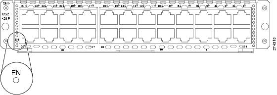
All Cisco enhanced EtherSwitch service modules have an enable (EN) LED. This LED indicates that the module has passed its self-test and is available to the router. (See Figure 11.) Table 3 lists the EN LED colors and their meanings.
Figure 11 EN LED
Port LEDs
Each port has a port LED. These port LEDs, as a group or individually, display information about the module and about the individual ports.
Table 4 explains how to interpret the port LED colors for link status on the Cisco enhanced EtherSwitch service modules.
Power Considerations
This section describes the power considerations for the router and Cisco enhanced EtherSwitch service modules:
•
•

Warning
Power Considerations for the Router
Cisco 2900 series and Cisco 3900 series routers supply -48 V power internally (with AC-PoE power supplies) to the Cisco enhanced EtherSwitch service modules.
Power Considerations for the Service Module
The Cisco enhanced EtherSwitch service module supports inline powering of IP phones with -48 V power. This allows IP phones to be plugged into a standard RJ-45 jack and be powered from the switch rather than from an AC wall outlet.
The Cisco enhanced EtherSwitch service module distributes the -48 V power to each of the Ethernet ports that are configured for PoE. Each port can be independently configured for PoE.
Connecting to the Enhanced EtherSwitch Service Module Ports
Both FE and GE ports are used to connect PCs or workstations to the network.
A 10/100/1000 Gigabit Ethernet (GE) port or a SFP module port can be used as an uplink port to connect to another router or a server, or can trunk to another Cisco enhanced EtherSwitch service module or switch located in the same chassis or in a separate installation.
Note
Connecting a FE or GE port to the network requires a Category 5 cable with RJ-45 male connectors, not provided with the switch module. Category 5 cables are widely available.
Related Documents
Hardware installation instructions for network modules
General information about configuration and command reference.
Regulatory compliance information for Cisco 2900 series routers.
Regulatory Compliance and Safety Information for Cisco 2900 Series Integrated Services Routers
Regulatory compliance information for Cisco 3900 series routers.
Regulatory Compliance and Safety Information for Cisco 3900 Series Integrated Services Routers
Obtaining Documentation, Obtaining Support, and Security Guidelines
For information on obtaining documentation, obtaining support, providing documentation feedback, security guidelines, and also recommended aliases and general Cisco documents, see the monthly What's New in Cisco Product Documentation, which also lists all new and revised Cisco technical documentation, at:
http://www.cisco.com/en/US/docs/general/whatsnew/whatsnew.html
CCDE, CCENT, CCSI, Cisco Eos, Cisco Explorer, Cisco HealthPresence, Cisco IronPort, the Cisco logo, Cisco Nurse Connect, Cisco Pulse, Cisco SensorBase, Cisco StackPower, Cisco StadiumVision, Cisco TelePresence, Cisco TrustSec, Cisco Unified Computing System, Cisco WebEx, DCE, Flip Channels, Flip for Good, Flip Mino, Flipshare (Design), Flip Ultra, Flip Video, Flip Video (Design), Instant Broadband, and Welcome to the Human Network are trademarks; Changing the Way We Work, Live, Play, and Learn, Cisco Capital, Cisco Capital (Design), Cisco:Financed (Stylized), Cisco Store, Flip Gift Card, and One Million Acts of Green are service marks; and Access Registrar, Aironet, AllTouch, AsyncOS, Bringing the Meeting To You, Catalyst, CCDA, CCDP, CCIE, CCIP, CCNA, CCNP, CCSP, CCVP, Cisco, the Cisco Certified Internetwork Expert logo, Cisco IOS, Cisco Lumin, Cisco Nexus, Cisco Press, Cisco Systems, Cisco Systems Capital, the Cisco Systems logo, Cisco Unity, Collaboration Without Limitation, Continuum, EtherFast, EtherSwitch, Event Center, Explorer, Follow Me Browsing, GainMaker, iLYNX, IOS, iPhone, IronPort, the IronPort logo, Laser Link, LightStream, Linksys, MeetingPlace, MeetingPlace Chime Sound, MGX, Networkers, Networking Academy, PCNow, PIX, PowerKEY, PowerPanels, PowerTV, PowerTV (Design), PowerVu, Prisma, ProConnect, ROSA, SenderBase, SMARTnet, Spectrum Expert, StackWise, WebEx, and the WebEx logo are registered trademarks of Cisco and/or its affiliates in the United States and certain other countries.
All other trademarks mentioned in this document or website are the property of their respective owners. The use of the word partner does not imply a partnership relationship between Cisco and any other company. (1002R)
Any Internet Protocol (IP) addresses used in this document are not intended to be actual addresses. Any examples, command display output, and figures included in the document are shown for illustrative purposes only. Any use of actual IP addresses in illustrative content is unintentional and coincidental.
© 2009 Cisco Systems, Inc. All rights reserved.
 Feedback
Contact Cisco
- Open a Support Case

- (Requires a Cisco Service Contract)