Configuring the SM-1-STM1
To continue your SM-1-STM1 service module installation, you must configure the STM-1 interface.
This chapter contains the following sections:
Configuring the Interface
After you verify that the new SM-1-STM1 is installed correctly (the ENABLED LED is lit), use the privileged-level configure command to configure the new interface. Have the following information available:
•![]() Protocols you plan to route on each new interface
Protocols you plan to route on each new interface
•![]() IP addresses, if you plan to configure the interfaces for IP routing
IP addresses, if you plan to configure the interfaces for IP routing
•![]() Bridging protocols you plan to use
Bridging protocols you plan to use
If you installed a new SM-1-STM1, or to change the configuration of an existing interface, you must enter configuration mode to configure the new interfaces. If you replaced a SM-1-STM1 that was previously configured, the system recognizes the new interfaces and brings each of them up in their existing configurations.
For a summary of the configuration options available and instructions for configuring interfaces on a SM-1-STM1, refer to the appropriate configuration publications listed in the "Related Documentation" section on page 5.
This section contains the following subsections:
•![]() Performing a Basic Interface Configuration
Performing a Basic Interface Configuration
•![]() Configuring the AU-3s and TUG-3s of a SM-1-STM1
Configuring the AU-3s and TUG-3s of a SM-1-STM1
•![]() Configuring an E1 Unframed Channel
Configuring an E1 Unframed Channel
•![]() Using show Commands to Verify the New Interface Status
Using show Commands to Verify the New Interface Status
•![]() Using the ping Command to Verify Network Connectivity
Using the ping Command to Verify Network Connectivity
Shutting Down an Interface
Before you remove an interface that you will not replace, or replace service modules, use the shutdown command to shut down (disable) the interfaces to prevent anomalies when you reinstall the new or reconfigured SM. When you shut down an interface, it is designated administratively down in the show command displays.
SUMMARY STEPS
1. ![]() enable
enable
2. ![]() configure terminal
configure terminal
3. ![]() interface serial slot/port
interface serial slot/port
4. ![]() shutdown
shutdown
5. ![]() copy running-config startup-config
copy running-config startup-config
6. ![]() show interfaces serial slot/port
show interfaces serial slot/port
DETAILED STEPS

Note ![]() To shut down additional interfaces, enter the interface serial command (followed by the interface address of the interface) for each of the interfaces on your SM. Use the no shutdown command to enable the interface.
To shut down additional interfaces, enter the interface serial command (followed by the interface address of the interface) for each of the interfaces on your SM. Use the no shutdown command to enable the interface.
Performing a Basic Interface Configuration
Following are instructions for a basic configuration, which include enabling an interface and configuring the SONET controller. You might also need to enter other configuration subcommands, depending on the requirements for your system configuration and the protocols you plan to route on the interface. For complete descriptions of configuration subcommands and the configuration options available for SONET interfaces, refer to the appropriate software documentation.
In the following procedure, press the Enter key after each step unless otherwise noted. At any time you can exit the privileged level and return to the user level by entering disable at the prompt as follows:
Router# disable
Router>
SUMMARY STEPS
1. ![]() enable
enable
2. ![]() configure terminal
configure terminal
3. ![]() controller sonet slot/port
controller sonet slot/port
4. ![]() clock source {internal | line}
clock source {internal | line}
5. ![]() end
end
6. ![]() copy running-config startup-config
copy running-config startup-config
DETAILED STEPS
Configuring the AU-3s and TUG-3s of a SM-1-STM1
You can configure each of the administrative unit groups (AUGs) and tributary unit groups (TUGs) of a SM-1-STM1 to carry a set of E1 links that are mapped into TU-12s (see Figure 4-1).
Figure 4-1
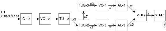
SM-1-STM1 Multiplexing Structure
Configuring an E1 Unframed Channel
To create an unframed or clear channel logical channel group on an E1 line, use the tug-2 tug-2# e1 e1# unframed command, as shown in the example below:
Router(config)# controller sonet 3/0
Router(config-controller)# au-4 1 tug-3 2
Router(config-controller-tug3)# tug-2 4 e1 1 unframed
Note ![]() The channel group is always 0 for unframed E1 lines.
The channel group is always 0 for unframed E1 lines.
Checking the Configuration
After configuring the new interface, use the show commands to display the status of the new interface or all interfaces, and use the ping and loopback commands to check connectivity. This section includes the following subsections:
•![]() Using show Commands to Verify the New Interface Status
Using show Commands to Verify the New Interface Status
•![]() Using the ping Command to Verify Network Connectivity
Using the ping Command to Verify Network Connectivity
Using show Commands to Verify the New Interface Status
This section demonstrates how you can use the show commands to verify that new interfaces are configured and operating correctly and that the module appears in them correctly. Sample displays of the output of selected show commands appear in the sections that follow. For complete command descriptions and examples, refer to the publications listed in the "Related Documentation" section on page 5.
If an interface is shut down and you configured it as up, or if the displays indicate that the hardware is not functioning properly, ensure that the interface is properly connected and terminated. If you still have problems bringing up the interface, contact a service representative for assistance.
This section includes the following subsections:
•![]() Using the show controllers Commands
Using the show controllers Commands
•![]() Using the show protocols Command
Using the show protocols Command
•![]() Using the show running-config Command
Using the show running-config Command
•![]() Using the show startup-config Command
Using the show startup-config Command
•![]() Using the show version or show hardware Commands
Using the show version or show hardware Commands
•![]() Using the show interfaces Command
Using the show interfaces Command
Using the show controllers Commands
Display all the current interface processors and their interfaces using the show controllers command.
Note ![]() The outputs that appear in this document may not match the output you receive when running these commands. The outputs in this document are examples only.
The outputs that appear in this document may not match the output you receive when running these commands. The outputs in this document are examples only.
The following is an example of the show controllers command:
Router# show controllers sonet 1/0
SONET 1/0 is up.
Hardware is single mode intermediate reach SM
H/W Version : 24.257.2.5, ROM Version : 1.2, F/W Version : 1.19.0
FREEDM version: 2, reset 0
Applique type is Channelized Sonet/SDH
Clock Source is Internal, AUG mapping is AU4.
Medium info:
Type: SDH, Line Coding: NRZ, Line Type: Short SM
Regenerator Section Status:
No alarms detected.
Multiplex Section Status:
No alarms detected.
No BER failure/degrade detected
BER_SF threshold power : 3
BER_SD threshold power : 6
Higher Order Path Status:
Path# 1 has no defects
Lower Order Path Status:
VC-12 1/1/1/1 has no defects
Using the show protocols Command
Display protocols configured for the entire system and for specific interfaces using the show protocols command.
Note ![]() The outputs that appear in this document may not match the output you receive when running these commands. The outputs in this document are examples only.
The outputs that appear in this document may not match the output you receive when running these commands. The outputs in this document are examples only.
The following is an example of the show protocols command:
Router# show protocols
line protocol is up
Using the show running-config Command
Display the running configuration file using the show running-config command.
Note ![]() The outputs that appear in this document may not match the output you receive when running these commands. The outputs in this document are examples only.
The outputs that appear in this document may not match the output you receive when running these commands. The outputs in this document are examples only.
The following is an example of the show running-config command:
Router# show running-config
controller SONET 1/0
framing sdh
!
au-4 1 tug-3 1
tug-2 1 e1 1 channel-group 1 timeslots 1-3
interface Serial1/0.1/1/1/1:1
ip address 1.1.1.1 255.255.255.0
Using the show startup-config Command
Display the configuration stored in the NVRAM using the show startup-config command.
Note ![]() The outputs that appear in this document may not match the output you receive when running these commands. The outputs in this document are examples only.
The outputs that appear in this document may not match the output you receive when running these commands. The outputs in this document are examples only.
The following is an example of the show startup-config command:
Router# show startup-config
Building configuration...
Current configuration : 27478 bytes
!
! Last configuration change at 13:23:45 IST Mon Jun 21 2010
!
version 15.1
service timestamps debug datetime msec localtime show-timezone
service timestamps log datetime msec localtime show-timezone
no service password-encryption
!
hostname 3945_PGIRI
!
boot-start-marker
boot-end-marker
!
!
enable password lab
!
no aaa new-model
clock timezone IST 5 0
!
no ipv6 cef
ip source-route
ip cef
!
!
!
!
!
multilink bundle-name authenticated
!
!
energywise domain cisco security shared-secret 0 cisco
!
crypto pki token default removal timeout 0
!
!
license udi pid C3900-SPE150/K9 sn FOC13522K4K
!
!
!
!
controller SHDSL 0/0/0
termination co
dsl-group pairs 0
!
controller SONET 1/0
framing sdh
clock source internal
!
au-4 1 tug-3 1
tug-2 1 e1 1 channel-group 1 timeslots 1-31
!
au-4 1 tug-3 2
tug-2 2 e1 1 unframed
!
au-4 1 tug-3 3
tug-2 1 e1 3 channel-group 30 timeslots 1
tug-2 3 e1 2 channel-group 17 timeslots 17
!
interface GigabitEthernet0/0
ip address 209.165.200.225 255.255.255.224
duplex auto
speed auto
!
interface GigabitEthernet0/1
mtu 1600
no ip address
shutdown
duplex auto
speed auto
!
interface GigabitEthernet0/2
mtu 1600
no ip address
shutdown
duplex auto
speed auto
!
interface Ethernet0/0/0
no ip address
tx-ring-limit 1
tx-queue-limit 1
!
interface Serial0/3/0
ip address 209.165.200.254 255.255.255.224
!
!
ip forward-protocol nd
!
no ip http server
no ip http secure-server
!
ip route 0.0.0.0 0.0.0.0 GigabitEthernet0/0
ip route 2209.165.201.1 255.255.255.224 209.165.201.30
!
!
!
snmp-server community public RW
!
control-plane
!
!
line con 0
exec-timeout 0 0
line aux 0
line vty 0 4
login
transport input all
!
!
exception data-corruption buffer truncate
scheduler allocate 20000 1000
end
Using the show version or show hardware Commands
Display the configuration of the system hardware, the number of each interface type installed, the Cisco IOS software version, the names and sources of configuration files, and the boot images, using the show version (or show hardware) command.
Note ![]() The outputs that appear in this document may not match the output you receive when running these commands. The outputs in this document are examples only.
The outputs that appear in this document may not match the output you receive when running these commands. The outputs in this document are examples only.
Example Output of the show version Command
Following is an example of the show version command from a Cisco 3945 ISR router with a SM-1-STM1 installed:
Router# show version
Cisco IOS Software, C3900 Software (C3900-UNIVERSALK9-M), 15.1(20100617:043914)
Copyright (c) 1986-2010 by Cisco Systems, Inc.
Compiled Thu 17-Jun-10 11:54 by anybody
ROM: System Bootstrap, Version 15.0(1r)M1, RELEASE SOFTWARE (fc1)
3945_PGIRI uptime is 5 hours, 5 minutes
System returned to ROM by reload at 08:16:36 IST Mon Jun 21 2010
System image file is "flash:c3900-universalk9-mz.SSA.last"
Last reload type: Normal Reload
Last reload reason: Reload Command
This product contains cryptographic features and is subject to United
States and local country laws governing import, export, transfer and
use. Delivery of Cisco cryptographic products does not imply
third-party authority to import, export, distribute or use encryption.
Importers, exporters, distributors and users are responsible for
compliance with U.S. and local country laws. By using this product you
agree to comply with applicable laws and regulations. If you are unable
to comply with U.S. and local laws, return this product immediately.
A summary of U.S. laws governing Cisco cryptographic products may be found at:
http://www.cisco.com/wwl/export/crypto/tool/stqrg.html
If you require further assistance please contact us by sending email to
export@cisco.com.
Cisco CISCO3945-CHASSIS (revision 1.0) with C3900-SPE150/K9 with 980992K/67584K bytes of
memory.
Processor board ID FHK1402F1YL
1 DSL controller
1 Ethernet interface
3 Gigabit Ethernet interfaces
231 Serial interfaces
2 Channelized STM-1 ports
DRAM configuration is 72 bits wide with parity enabled.
255K bytes of non-volatile configuration memory.
126448K bytes of USB Flash usbflash0 (Read/Write)
254464K bytes of ATA System CompactFlash 0 (Read/Write)
License Info:
License UDI:
-------------------------------------------------
Device# PID SN
-------------------------------------------------
*0 C3900-SPE150/K9 FOC13522K4K
Technology Package License Information for Module:'c3900'
----------------------------------------------------------------
Technology Technology-package Technology-package
Current Type Next reboot
-----------------------------------------------------------------
ipbase ipbasek9 Permanent ipbasek9
security None None None
uc None None None
data None None None
Configuration register is 0x0
Using the show diag Command
Display the types of service modules installed in your system (and specific information about each) using the show diag slot command, where slot is the service module slot in a Cisco 3925 router or Cisco 3945 router.
Note ![]() The outputs that appear in this document may not match the output you receive when running these commands. The outputs in this document are examples only.
The outputs that appear in this document may not match the output you receive when running these commands. The outputs in this document are examples only.
Using the show interfaces Command
Display status information (including the physical slot and interface address) for the interfaces you specify using the show interfaces command.
For complete descriptions of interface subcommands and the configuration options available for the supported interfaces, refer to the publications listed in the "Related Documentation" section on page 5.
Note ![]() The outputs that appear in this document may not match the output you receive when running these commands. The outputs in this document are examples only.
The outputs that appear in this document may not match the output you receive when running these commands. The outputs in this document are examples only.
Example Output of the show interfaces Command
Following is an example of the show interfaces command from a Cisco 3945 ISR with a SM-1-STM1 installed:
Router> show interface serial
Router#sh int Serial1/0.1/1/1/1:1
Serial1/0.1/1/1/1:1 is up, line protocol is up
Hardware is Channelized STM-1 controller
Internet address is 1.1.1.2/24
MTU 1500 bytes, BW 192 Kbit/sec, DLY 20000 usec,
reliability 255/255, txload 1/255, rxload 65/255
Encapsulation HDLC, crc 16, loopback not set
Keepalive set (10 sec)
Last input 00:00:00, output never, output hang never
Last clearing of "show interface" counters never
Input queue: 0/75/0/0 (size/max/drops/flushes); Total output drops: 0
Queueing strategy: weighted fair
Output queue: 0/1000/64/0 (size/max total/threshold/drops)
Conversations 0/1/16 (active/max active/max total)
Reserved Conversations 0/0 (allocated/max allocated)
Available Bandwidth 144 kilobits/sec
5 minute input rate 49000 bits/sec, 23 packets/sec
5 minute output rate 0 bits/sec, 0 packets/sec
5507 packets input, 1785932 bytes, 0 no buffer
Received 30 broadcasts (0 IP multicasts)
0 runts, 0 giants, 0 throttles
0 input errors, 0 CRC, 0 frame, 0 overrun, 0 ignored, 0 abort
35 packets output, 2995 bytes, 0 underruns
0 output errors, 0 collisions, 1 interface resets
0 unknown protocol drops
0 output buffer failures, 0 output buffers swapped out
0 carrier transitions no alarm present
Timeslot(s) Used: 1-3, subrate: 192Kb/s, transmit delay is 0 flags
non-inverted data
Router#
Using the ping Command to Verify Network Connectivity
Using the ping command, you can verify that an interface port is functioning properly. This section provides a brief description of this command. Refer to the publications listed in the "Related Documentation" section on page 5 for detailed command descriptions and examples.
The ping command sends echo request packets out to a remote device at an IP address that you specify. After sending an echo request, the system waits a specified time for the remote device to reply. Each echo reply is displayed as an exclamation point (!) on the console terminal; each request that is not returned before the specified timeout is displayed as a period (.). A series of exclamation points (!!!!!) indicates a good connection; a series of periods (.....) or the messages [timed out] or [failed] indicate a bad connection.
Following is an example of a successful ping command to a remote server with the address 10.0.0.10:
Router# ping 10.0.0.10 <Return>
Type escape sequence to abort.
Sending 5, 100-byte ICMP Echoes to 10.0.0.10, timeout is 2 seconds:
!!!!!
Success rate is 100 percent (5/5), round-trip min/avg/max = 1/15/64 ms
Router#
If the connection fails, verify that you have the correct IP address for the destination and that the device is active (powered on), and repeat the ping command.
Proceed to the, "Using loopback Commands" section, to finish checking network connectivity.
Using loopback Commands
With the loopback test, you can detect and isolate equipment malfunctions by testing the connection between the SM-1-STM1 interface and a remote device such as a multiplexer interface. The loopback subcommand places an interface in loopback mode, which enables test packets that are generated from the ping command to loop through a remote device. If the packets complete the loop, the connection is good. If not, you can isolate a fault to the remote device in the path of the loopback test.
The SM-1-STM1 supports two loopback modes at the sonet controller level: local and network.
Use the loopback {local | network} command to set the loopback mode, as shown below:
Router(config)# controller sonet 3/0
Router(config-controller)# loopback network
When the loopback local command is used, all data transmitted to the network is internally looped back to the receiver. In this loopback mode, the serial interfaces should go into up/up looped state.
When the loopback network command is used, all data received from the connected device is transmitted back unchanged. In this loopback mode, T1 serial interfaces are not working.
The SM-1-STM1 also supports loopback on E1 lines mapped to a TUG-3 or AU-3.
To specify a loopback on an E1 line that has been mapped to a TUG-3, use the tug-2 e1 loopback command in configuration controller tug3 mode.
To specify a loopback on an E1 line that has been mapped to an AU-3, use the tug-2 e1 loopback command in configuration controller au3 mode.
The complete tug-2 e1 loopback command syntax is:
tug-2 tug-2 number e1 e1-number loopback {local | network {line | payload}}
To disable the loopback, use the no form of this command:
[no] tug-2 tug-2 number e1 e1-number loopback {local | network {line | payload}}
 Feedback